LAND ROVER FRELANDER 2 2006 Repair Manual
Manufacturer: LAND ROVER, Model Year: 2006, Model line: FRELANDER 2, Model: LAND ROVER FRELANDER 2 2006Pages: 3229, PDF Size: 78.5 MB
Page 901 of 3229
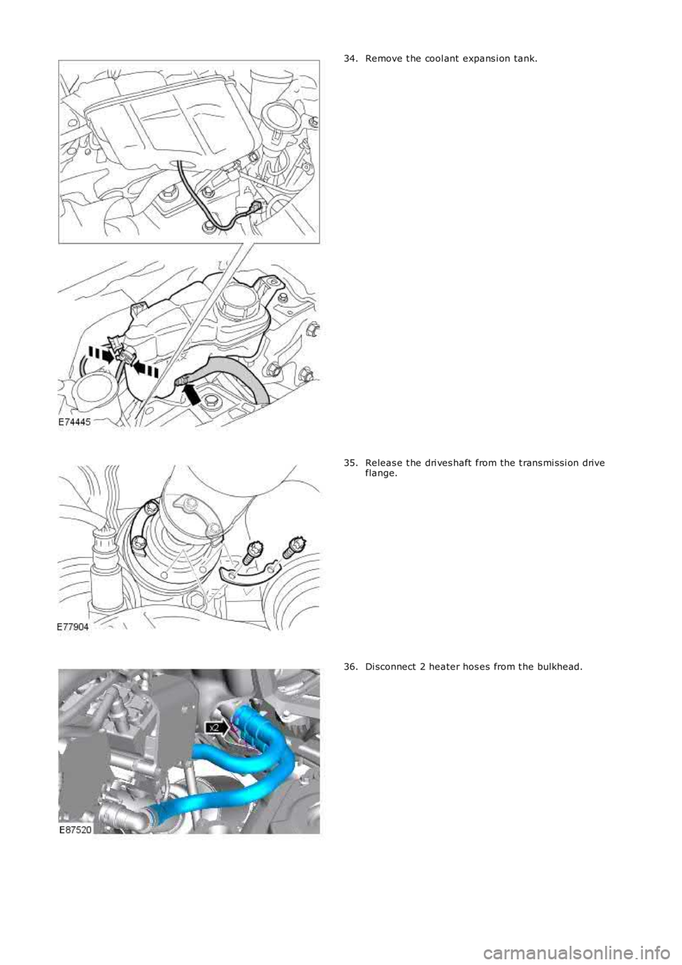
Remove t he cool ant expans i on tank.34.
Releas e t he dri ves haft from the t rans mi ss i on driveflange.35.
Di sconnect 2 heater hos es from t he bulkhead.36.
Page 902 of 3229
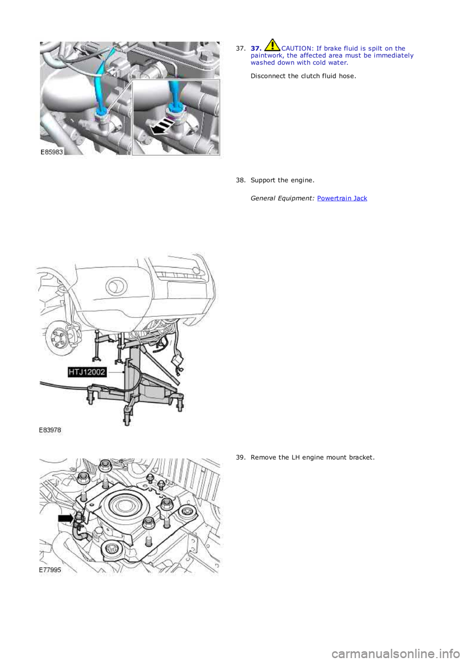
37. CAUTION: If brake fl uid i s s pilt on the
paint work, the affected area mus t be i mmediat el y
was hed down wit h cold wat er.
Di sconnect t he cl utch fluid hos e.
37. Support the engi ne.
General Equi pment: Powert rai n Jack 38.
Remove t he LH engine mount bracket .
39.
Page 903 of 3229
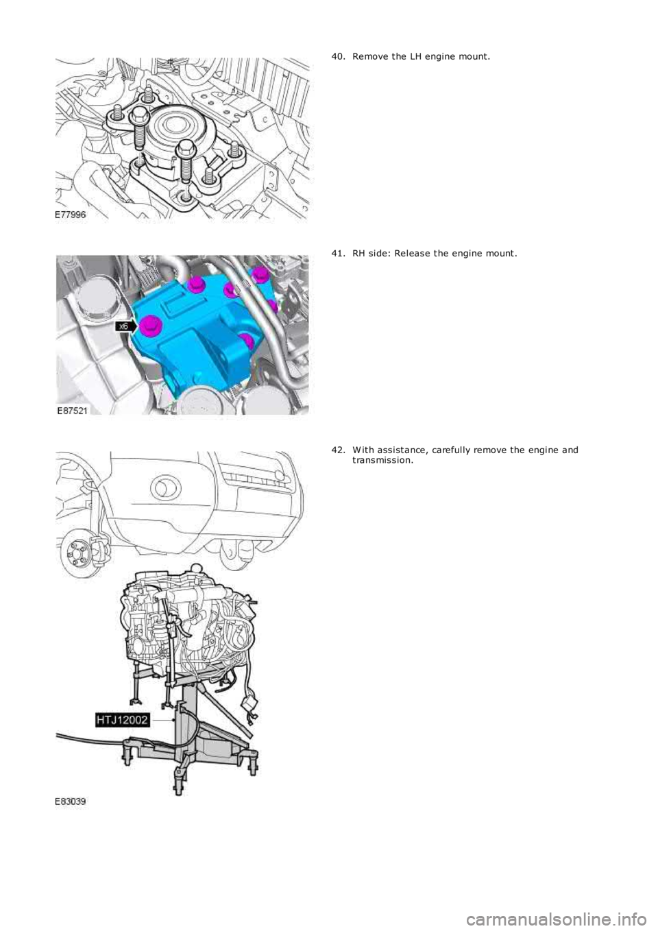
Remove t he LH engine mount.40.
RH si de: Rel eas e t he engine mount .41.
W it h ass i st ance, careful ly remove the engi ne andt rans mis s ion.42.
Page 904 of 3229
Publi s hed: 11-May-2011
Engine - TD4 2.2L Diesel - Engine
Installation
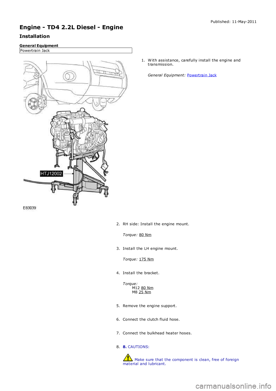
General Equipment Powert rai n Jack W it h ass i st ance, careful ly i nst all t he engi ne and
t rans mis s ion.
General Equi pment: Powert rai n Jack 1.
RH si de: Ins tall t he engine mount .
T orque: 80 Nm 2.
Inst all t he LH engine mount.
T orque: 175 Nm 3.
Inst all t he bracket .
T orque: M12 80 Nm M8
25 Nm 4.
Remove t he engi ne s upport .
5.
Connect t he clutch flui d hose.
6.
Connect t he bulkhead heat er hos es.
7.
8. CAUTIONS: Make s ure that t he component is cl ean, free of foreign
mat eri al and l ubricant.
8.
Page 905 of 3229
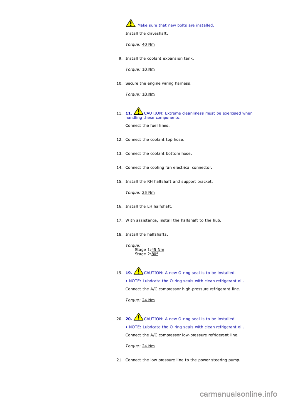
Stage 1:
Stage 2: Make s ure that new bolt s are ins t al led.
Inst all t he dri ves haft .
T orque: 40 Nm Inst all t he cool ant expans i on tank.
T orque: 10 Nm 9.
Secure t he engi ne wiring harnes s .
T orque: 10 Nm 10.
11. CAUTION: Extreme cleanli nes s mus t be exercis ed when
handl ing t hese components .
Connect t he fuel li nes .
11.
Connect t he cool ant t op hos e.
12.
Connect t he cool ant bot tom hos e.
13.
Connect t he cool ing fan electrical connect or.
14.
Inst all t he RH halfs haft and s upport bracket.
T orque: 25 Nm 15.
Inst all t he LH halfshaft.
16.
W it h ass i st ance, i ns t all the hal fs haft t o t he hub.
17.
Inst all t he hal fs haft s .
T orque: 45 Nm 80°18.
19. CAUTION: A new O-ring s eal is t o be ins tall ed.
• NOTE: Lubri cat e t he O-ring s eals wit h clean refri gerant oil.
Connect t he A/C compress or high-press ure refri gerant line.
T orque: 24 Nm 19.
20. CAUTION: A new O-ring s eal is t o be ins tall ed.
• NOTE: Lubri cat e t he O-ring s eals wit h clean refri gerant oil.
Connect t he A/C compress or low-pres s ure refrigerant li ne.
T orque: 24 Nm 20.
Connect t he low pres sure li ne t o t he power s t eering pump.
21.
Page 906 of 3229
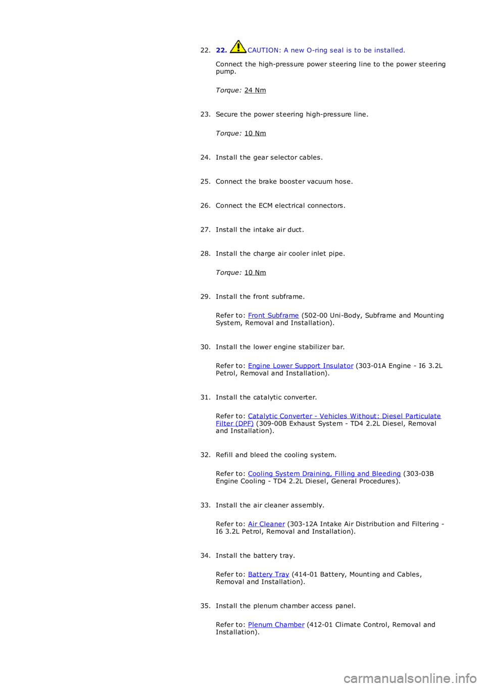
22. CAUTION: A new O-ring s eal is t o be ins tall ed.
Connect t he high-press ure power s t eering l ine t o t he power st eeri ng
pump.
T orque: 24 Nm 22.
Secure t he power s t eering hi gh-pres s ure l ine.
T orque: 10 Nm 23.
Inst all t he gear s elector cables .
24.
Connect t he brake boost er vacuum hos e.
25.
Connect t he ECM elect rical connectors .
26.
Inst all t he int ake ai r duct .
27.
Inst all t he charge air cool er inlet pipe.
T orque: 10 Nm 28.
Inst all t he front subframe.
Refer t o: Front Subframe (502-00 Uni -Body, Subframe and Mount ing
Syst em, Removal and Ins tall ati on).
29.
Inst all t he lower engi ne s tabil izer bar.
Refer t o: Engi ne Lower Support Ins ulat or (303-01A Engine - I6 3.2L
Petrol, Removal and Ins tall ati on).
30.
Inst all t he cat alyti c convert er.
Refer t o: Cat alyt ic Converter - Vehicles W it hout : Di es el Part iculate Fil ter (DPF) (309-00B Exhaus t Syst em - TD4 2.2L Di es el, Removal
and Inst all at ion).
31.
Refi ll and bleed t he cool ing s ys tem.
Refer t o: Cool ing Sys tem Drai ni ng, Fi lli ng and Bleeding (303-03B
Engine Cooli ng - TD4 2.2L Di esel , General Procedures ).
32.
Inst all t he air cleaner as s embly.
Refer t o: Air Cleaner (303-12A Intake Ai r Dis tribut ion and Fil tering -
I6 3.2L Pet rol, Removal and Ins t al lat ion).
33.
Inst all t he bat t ery t ray.
Refer t o: Bat t ery Tray (414-01 Bat tery, Mount ing and Cables ,
Removal and Ins tall ati on).
34.
Inst all t he plenum chamber access panel.
Refer t o: Plenum Chamber (412-01 Cl imat e Control, Removal and
Inst all at ion).
35.
Page 907 of 3229
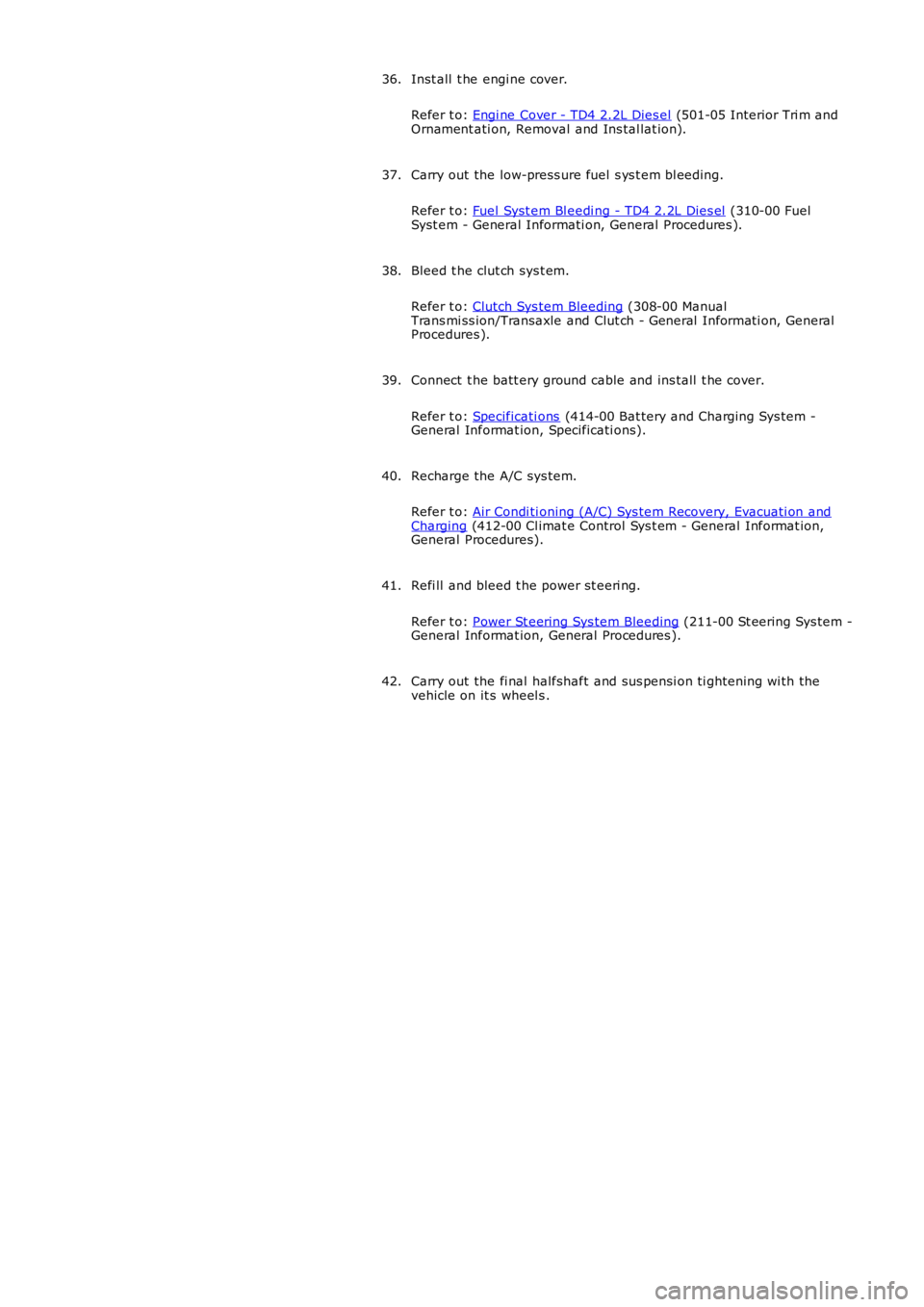
Inst all t he engi ne cover.
Refer t o: Engi ne Cover - TD4 2.2L Dies el (501-05 Interior Tri m andOrnament ati on, Removal and Ins tal lat ion).
36.
Carry out the low-press ure fuel s ys t em bl eedi ng.
Refer t o: Fuel Syst em Bl eedi ng - TD4 2.2L Dies el (310-00 FuelSyst em - General Informati on, General Procedures ).
37.
Bleed t he clut ch sys t em.
Refer t o: Clutch Sys tem Bleeding (308-00 ManualTrans mi ss ion/Transaxle and Clut ch - General Informati on, GeneralProcedures ).
38.
Connect t he batt ery ground cable and ins tall t he cover.
Refer t o: Specificati ons (414-00 Bat tery and Charging Sys tem -General Informat ion, Specificati ons).
39.
Recharge the A/C sys tem.
Refer t o: Air Condi ti oning (A/C) Sys tem Recovery, Evacuati on andCharging (412-00 Cl imat e Control Sys t em - General Informat ion,General Procedures).
40.
Refi ll and bleed t he power st eeri ng.
Refer t o: Power St eering Sys tem Bleeding (211-00 St eering Sys tem -General Informat ion, General Procedures ).
41.
Carry out the fi nal halfshaft and sus pensi on ti ghtening wi th thevehicle on it s wheel s .42.
Page 908 of 3229
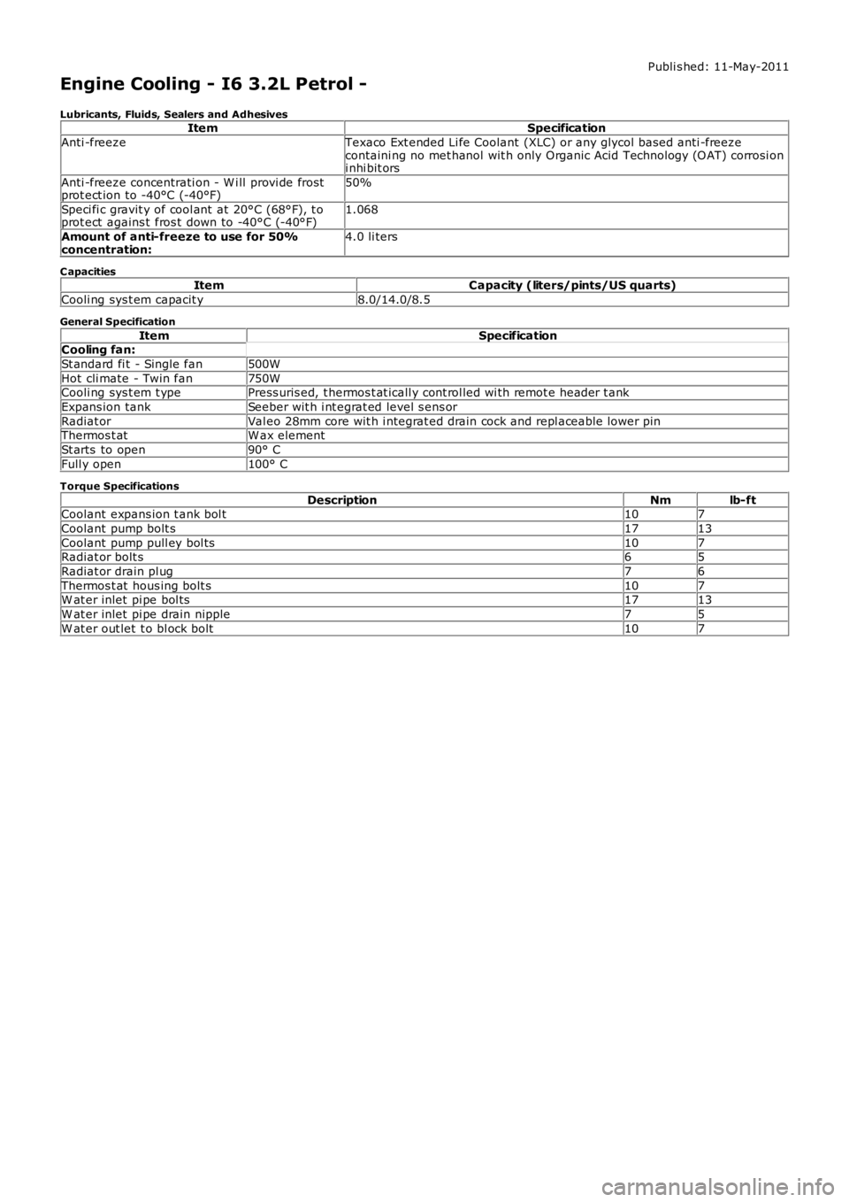
Publi s hed: 11-May-2011
Engine Cooling - I6 3.2L Petrol -
Lubricants, Fluids, Sealers and AdhesivesItemSpecification
Anti -freezeTexaco Ext ended Li fe Coolant (XLC) or any glycol bas ed anti -freezecontaini ng no met hanol wit h only Organic Acid Technology (O AT) corrosi oni nhi bit ors
Anti -freeze concentrati on - W i ll provi de frostprot ect ion to -40°C (-40°F)50%
Speci fi c gravit y of cool ant at 20°C (68°F), t oprot ect agains t fros t down to -40°C (-40°F)1.068
Amount of anti-freeze to use for 50%concentration:4.0 li ters
C apacitiesItemCapacity (liters/pints/US quarts)
Cooli ng sys t em capacit y8.0/14.0/8.5
General Specification
ItemSpecificationCooling fan:
St andard fi t - Single fan500W
Hot cli mate - Twin fan750WCooli ng sys t em t ypePress uris ed, t hermos t at icall y cont rol led wi th remot e header t ank
Expans ion tankSeeber wit h i nt egrat ed level s ens or
Radiat orVal eo 28mm core wit h i ntegrat ed drain cock and repl aceable lower pinThermos t atW ax element
St arts to open90° C
Full y open100° C
Torque Specifications
DescriptionNmlb-ftCoolant expans ion t ank bol t107
Coolant pump bolt s1713
Coolant pump pull ey bol ts107Radiat or bolt s65
Radiat or drain pl ug76
Thermos t at hous ing bolt s107W at er inlet pi pe bol ts1713
W at er inlet pi pe drain nipple75
W at er out let t o bl ock bolt107
Page 909 of 3229
Publi s hed: 11-May-2011
Engine Cooling - I6 3.2L Petrol - Engine Cooling
Des cript ion and Operat ion
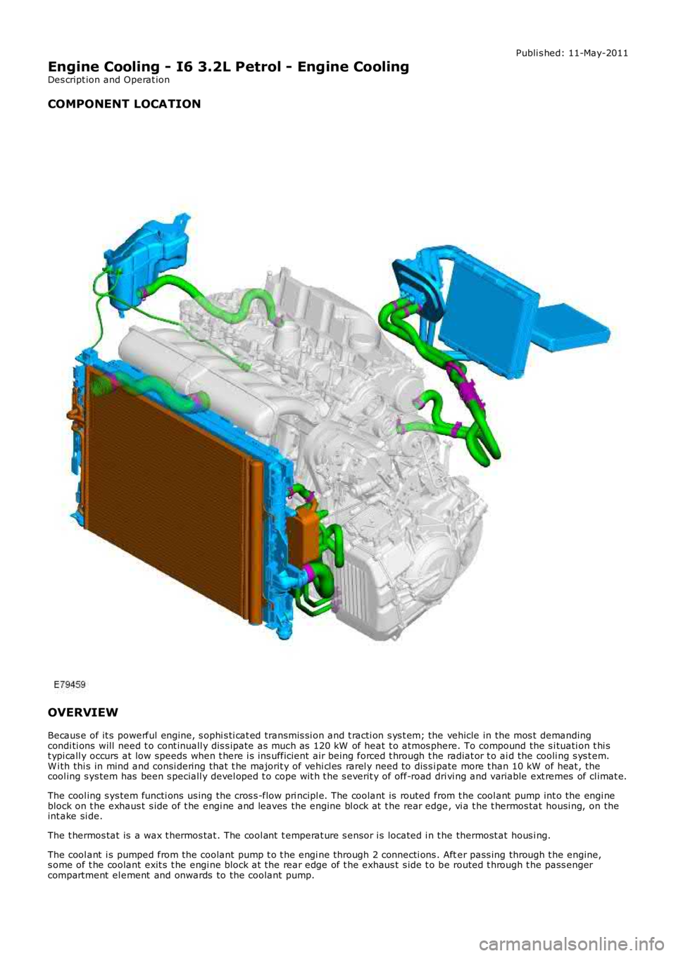
COMPONENT LOCATION
OVERVIEW
Becaus e of it s powerful engine, s ophi s ti cat ed transmis si on and t racti on s ys t em; the vehicle in the mos t demandingcondi ti ons will need t o cont inuall y dis s ipate as much as 120 kW of heat t o atmos phere. To compound the s i tuati on t hi st ypi call y occurs at low speeds when t here i s ins ufficient air being forced t hrough the radiat or t o ai d the cooli ng s ys t em.W i th thi s in mind and consi dering that t he majorit y of vehi cl es rarel y need to dis s ipate more t han 10 kW of heat , thecool ing s ys tem has been s peciall y devel oped t o cope wit h t he s everit y of off-road dri vi ng and variable ext remes of cl imat e.
The cool ing s ys tem functi ons us ing the cros s -flow pri ncipl e. The coolant is routed from t he cool ant pump int o the engi neblock on t he exhaus t s ide of t he engi ne and leaves the engine bl ock at t he rear edge, vi a t he t hermos tat housi ng, on theint ake si de.
The t hermos tat is a wax t hermos tat . The cool ant t emperat ure s ensor i s located i n t he thermost at hous i ng.
The cool ant i s pumped from the coolant pump t o t he engi ne through 2 connecti ons . After pass ing through t he engine,s ome of t he coolant exit s t he engi ne block at the rear edge of t he exhaus t s ide t o be routed t hrough t he pass engercompartment el ement and onwards to the coolant pump.
Page 910 of 3229
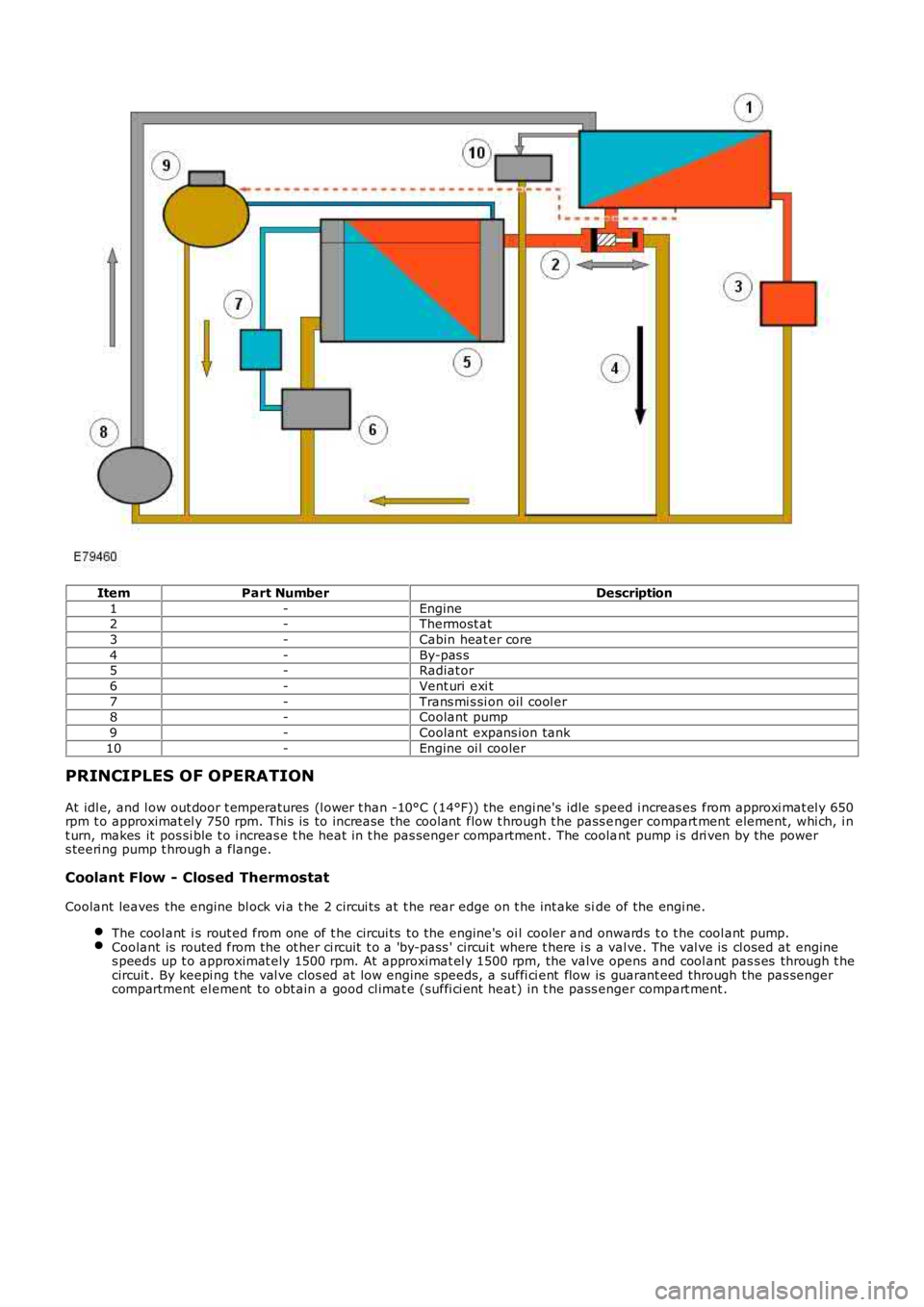
ItemPart NumberDescription
1-Engine2-Thermost at
3-Cabin heat er core
4-By-pas s5-Radiat or
6-Vent uri exi t
7-Trans mi s si on oil cool er8-Coolant pump
9-Coolant expans ion tank
10-Engine oi l cooler
PRINCIPLES OF OPERATION
At idl e, and l ow out door t emperatures (l ower t han -10°C (14°F)) the engi ne's idle s peed i ncreas es from approxi mat el y 650rpm t o approximat el y 750 rpm. Thi s is to increase the coolant flow t hrough t he pass enger compart ment element, whi ch, i nt urn, makes it pos si ble t o i ncreas e t he heat in t he pas senger compartment . The coolant pump i s dri ven by the powers teeri ng pump t hrough a flange.
Coolant Flow - Closed Thermostat
Coolant leaves the engine bl ock vi a t he 2 circui ts at t he rear edge on t he int ake side of the engi ne.
The cool ant i s rout ed from one of t he circui ts to t he engine's oi l cooler and onwards t o t he cool ant pump.Coolant is routed from the ot her ci rcuit t o a 'by-pass ' circui t where t here i s a valve. The val ve is cl osed at engines peeds up t o approximat ely 1500 rpm. At approximat el y 1500 rpm, the valve opens and cool ant pas s es through t hecircuit . By keepi ng t he val ve clos ed at low engine speeds, a suffi ci ent flow is guarant eed through the pas sengercompartment el ement to obt ain a good cl imat e (suffi ci ent heat) in t he pass enger compart ment .