LEXUS LS430 2003 Factory Repair Manual
Manufacturer: LEXUS, Model Year: 2003,
Model line: LS430,
Model: LEXUS LS430 2003
Pages: 4500, PDF Size: 87.45 MB
LEXUS LS430 2003 Factory Repair Manual
LS430 2003
LEXUS
LEXUS
https://www.carmanualsonline.info/img/36/57050/w960_57050-0.png
LEXUS LS430 2003 Factory Repair Manual
Trending: automatic transmission fluid, brake sensor, transmission fluid, B2419 bean, Rear suspension, Navi, fuel pump
Page 3521 of 4500
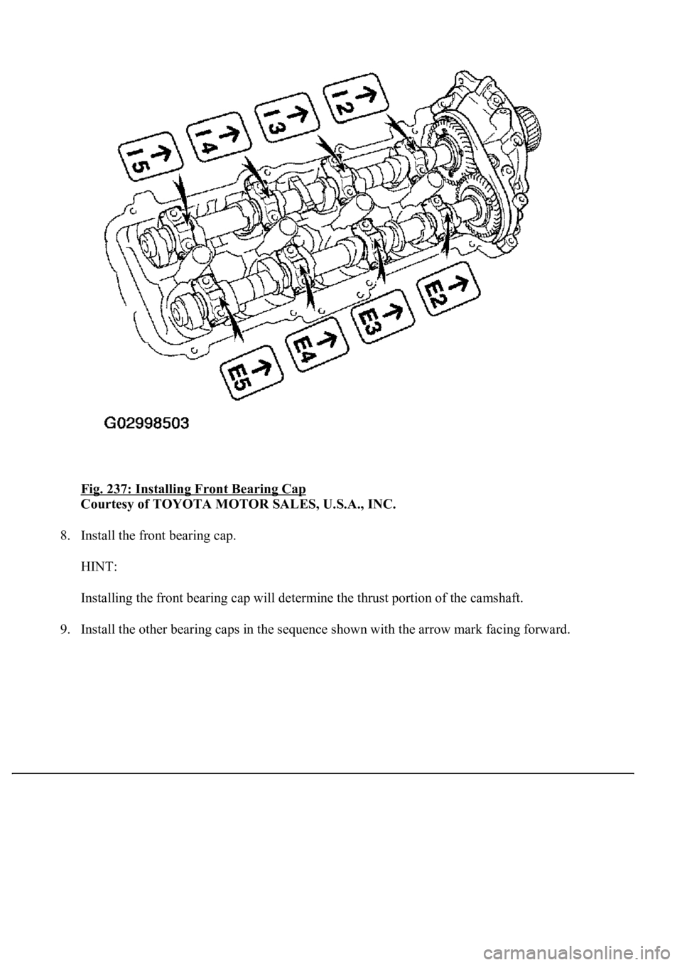
Fig. 237: Installing Front Bearing Cap
Courtesy of TOYOTA MOTOR SALES, U.S.A., INC.
8. Install the front bearing cap.
HINT:
Installing the front bearing cap will determine the thrust portion of the camshaft.
9. Install the other bearin
g caps in the sequence shown with the arrow mark facing forward.
Page 3522 of 4500
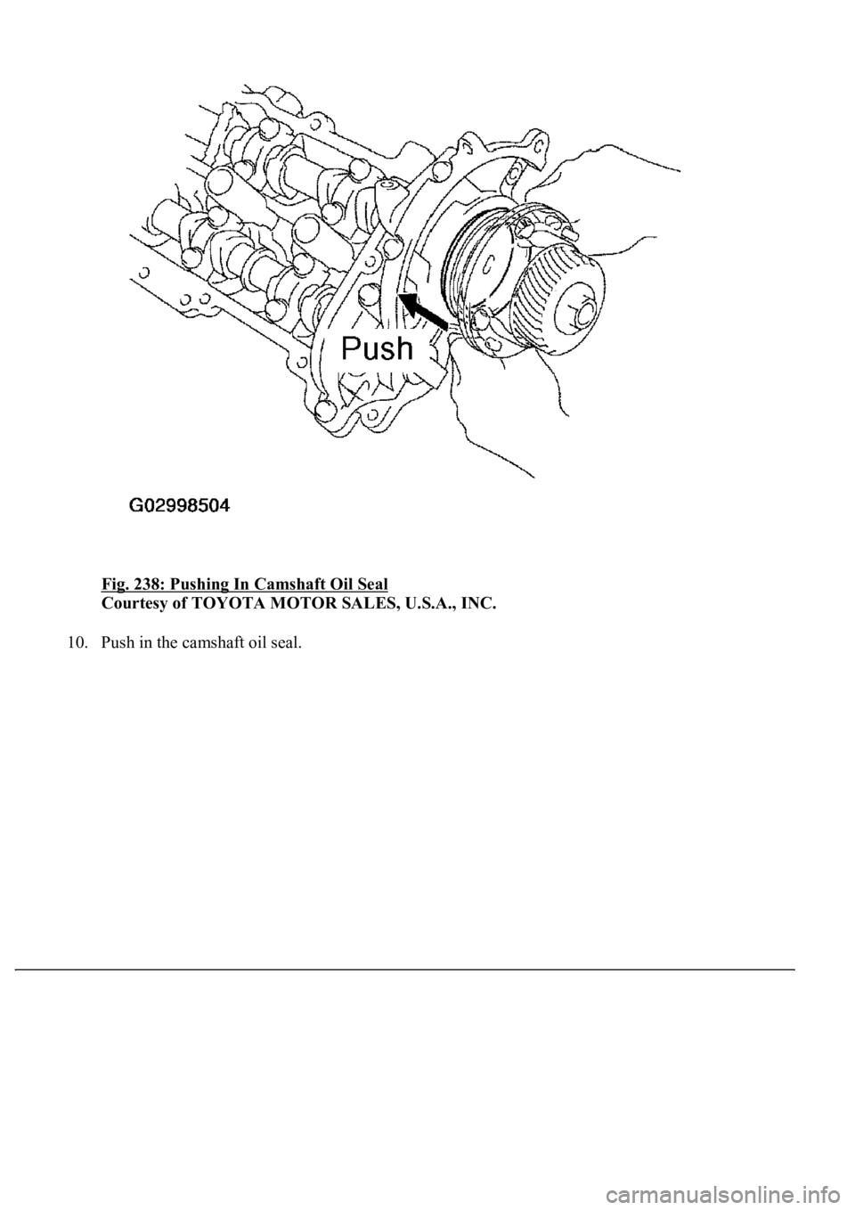
Fig. 238: Pushing In Camshaft Oil Seal
Courtesy of TOYOTA MOTOR SALES, U.S.A., INC.
10. Push in the camshaft oil seal.
Page 3523 of 4500
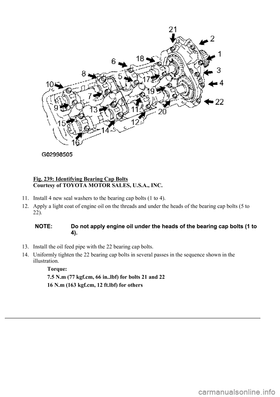
Fig. 239: Identifying Bearing Cap Bolts
Courtesy of TOYOTA MOTOR SALES, U.S.A., INC.
11. Install 4 new seal washers to the bearing cap bolts (1 to 4).
12. Apply a light coat of engine oil on the threads and under the heads of the bearing cap bolts (5 to
22).
13. Install the oil feed pipe with the 22 bearing cap bolts.
14. Uniformly tighten the 22 bearing cap bolts in several passes in the sequence shown in the
illustration.
Torque:
<001a0011001800030031001100500003000b001a001a0003004e004a0049001100460050000f0003001900190003004c005100110011004f00450049000c0003004900520055000300450052004f0057005600030015001400030044005100470003001500
15[
16 N.m (163 kgf.cm, 12 ft.lbf) for others
Page 3524 of 4500
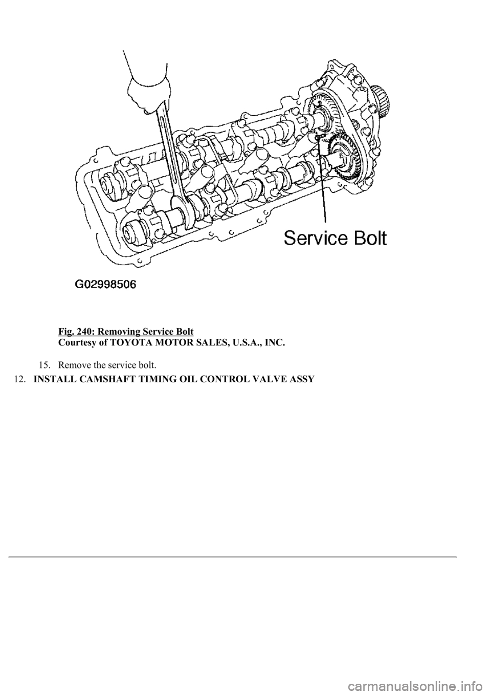
Fig. 240: Removing Service Bolt
Courtesy of TOYOTA MOTOR SALES, U.S.A., INC.
15. Remove the service bolt.
12.INSTALL CAMSHAFT TIMING OIL CONTROL VALVE ASSY
Page 3525 of 4500
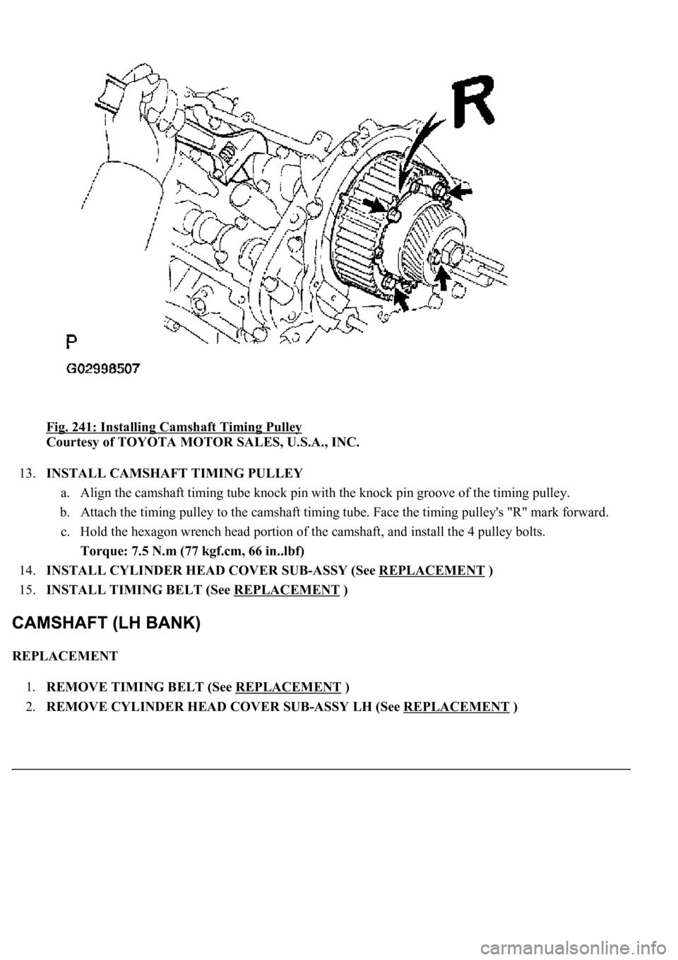
Fig. 241: Installing Camshaft Timing Pulley
Courtesy of TOYOTA MOTOR SALES, U.S.A., INC.
13.INSTALL CAMSHAFT TIMING PULLEY
a. Align the camshaft timing tube knock pin with the knock pin groove of the timing pulley.
b. Attach the timing pulley to the camshaft timing tube. Face the timing pulley's "R" mark forward.
c. Hold the hexagon wrench head portion of the camshaft, and install the 4 pulley bolts.
Torque: 7.5 N.m (77 kgf.cm, 66 in..lbf)
14.INSTALL CYLINDER HEAD COVER SUB-ASSY (See REPLACEMENT
)
15.INSTALL TIMING BELT (See REPLACEMENT
)
REPLACEMENT
1.REMOVE TIMING BELT (See REPLACEMENT
)
2.REMOVE CYLINDER HEAD COVER SUB-ASSY LH (See REPLACEMENT
)
Page 3526 of 4500
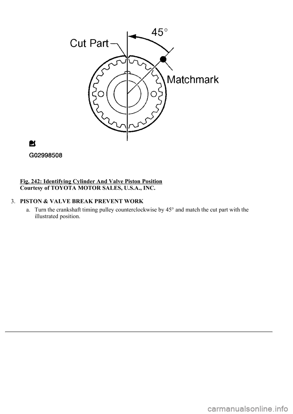
<0029004c004a00110003001500170015001d0003002c0047004800510057004c0049005c004c0051004a00030026005c004f004c00510047004800550003002400510047000300390044004f0059004800030033004c005600570052005100030033005200
56004c0057004c00520051[
Courtesy of TOYOTA MOTOR SALES, U.S.A., INC.
3.PISTON & VALVE BREAK PREVENT WORK
a. Turn the crankshaft timing pulley counterclockwise by 45° and match the cut part with the
illustrated position.
Page 3527 of 4500
Fig. 243: Removing Camshaft Timing Pulley Sub-Assy LH
Courtesy of TOYOTA MOTOR SALES, U.S.A., INC.
HINT:
When the No. 1 cylinder is positioned at 45° BTDC, the valve and piston do not interfere with each
other even when the valve is fully open.
Page 3528 of 4500
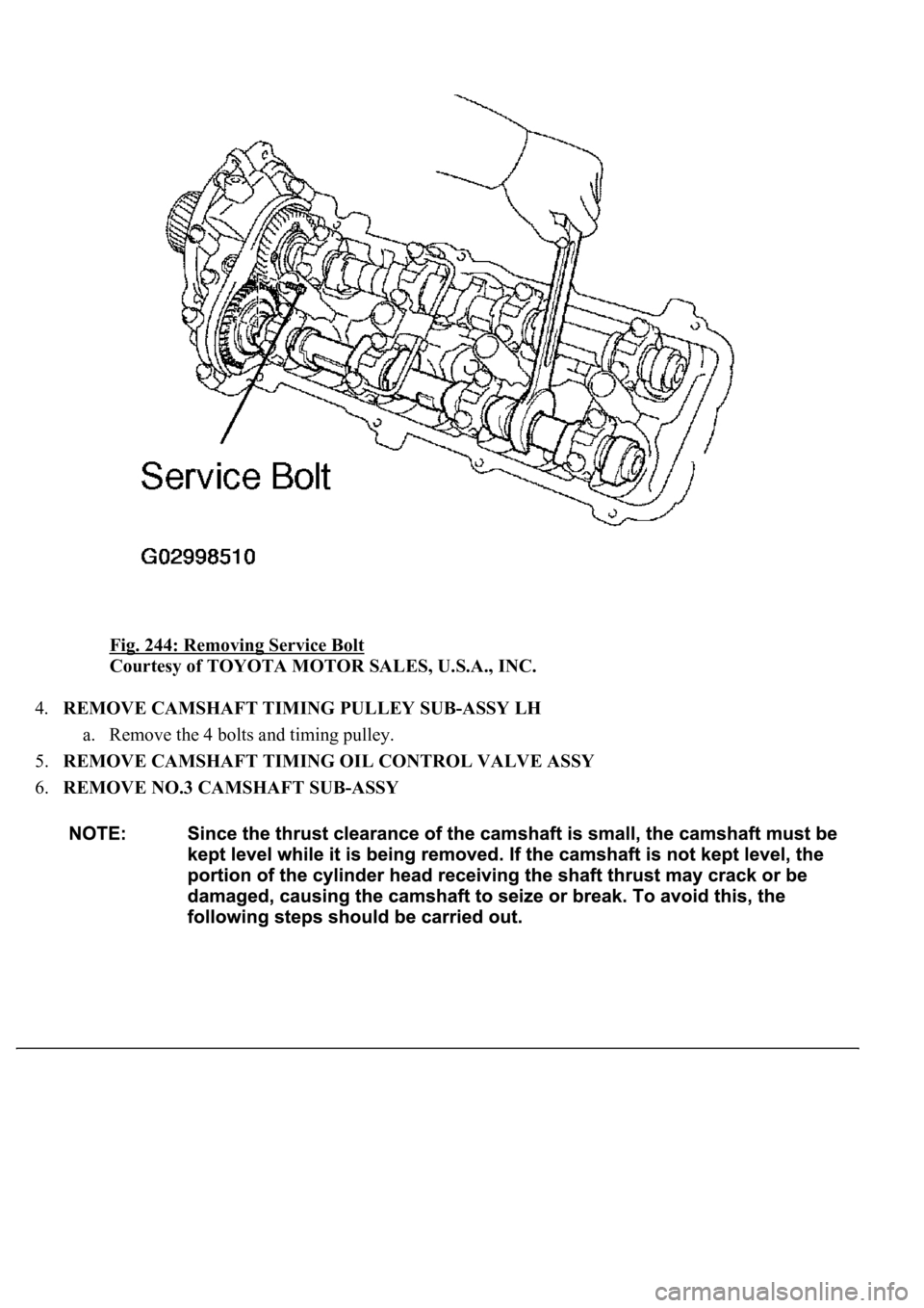
Fig. 244: Removing Service Bolt
Courtesy of TOYOTA MOTOR SALES, U.S.A., INC.
4.REMOVE CAMSHAFT TIMING PULLEY SUB-ASSY LH
a. Remove the 4 bolts and timing pulley.
5.REMOVE CAMSHAFT TIMING OIL CONTROL VALVE ASSY
6.REMOVE NO.3 CAMSHAFT SUB-ASSY
Page 3529 of 4500
<0029004c004a00110003001500170018001d00030036004800570057004c0051004a00030037004c0050004c0051004a0003003000440055004e00030032004900030026004400500056004b004400490057000300300044004c00510003002a0048004400
55[
Courtesy of TOYOTA MOTOR SALES, U.S.A., INC.
a. Bring the service bolt hole of the sub gear upward by turning the hexagon wrench head portion of
the exhaust camshaft with a wrench.
b. Secure the sub gear to the main gear with a service bolt.
RECOMMENDED SERVICE BOLT:
RECOMMENDED SERVICE BOLT
HINT:
When removin
g the camshaft, make sure that the torsional spring force of the sub gear has been
Thread diameter6mm
Thread pitch1.0 mm
Bolt length16 to 20 mm (0.63 to 0.79 in.)
Page 3530 of 4500
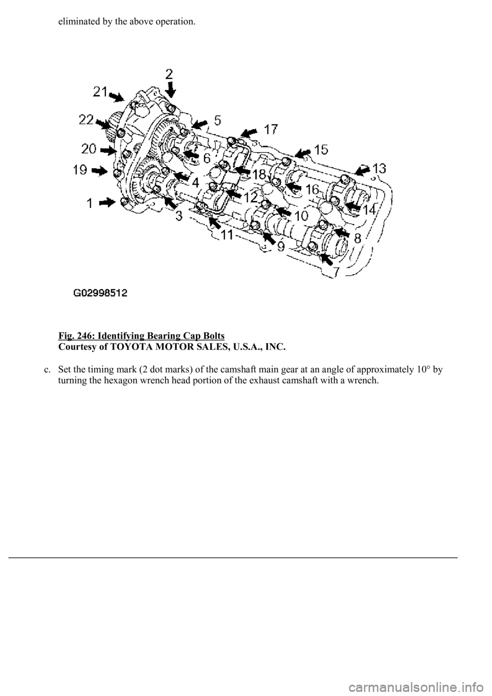
eliminated by the above operation.
Fig. 246: Identifying Bearing Cap Bolts
Courtesy of TOYOTA MOTOR SALES, U.S.A., INC.
c. Set the timing mark (2 dot marks) of the camshaft main gear at an angle of approximately 10° by
turning the hexagon wrench head portion of the exhaust camshaft with a wrench.
Trending: ABS, engine overheat, Rear, pcv, oxygen sensor, diagram, cylinder head
