LEXUS LS430 2003 Factory Repair Manual
Manufacturer: LEXUS, Model Year: 2003,
Model line: LS430,
Model: LEXUS LS430 2003
Pages: 4500, PDF Size: 87.45 MB
LEXUS LS430 2003 Factory Repair Manual
LS430 2003
LEXUS
LEXUS
https://www.carmanualsonline.info/img/36/57050/w960_57050-0.png
LEXUS LS430 2003 Factory Repair Manual
Trending: parking brake, boot, bulb, air suspension, tail light replacement, electronic modulated, Rear control Arm
Page 3481 of 4500
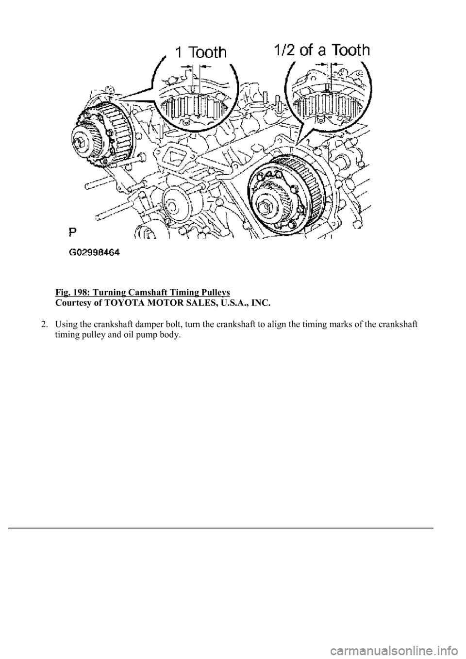
Fig. 198: Turning Camshaft Timing Pulleys
Courtesy of TOYOTA MOTOR SALES, U.S.A., INC.
2. Using the crankshaft damper bolt, turn the crankshaft to align the timing marks of the crankshaft
timin
g pulley and oil pump body.
Page 3482 of 4500
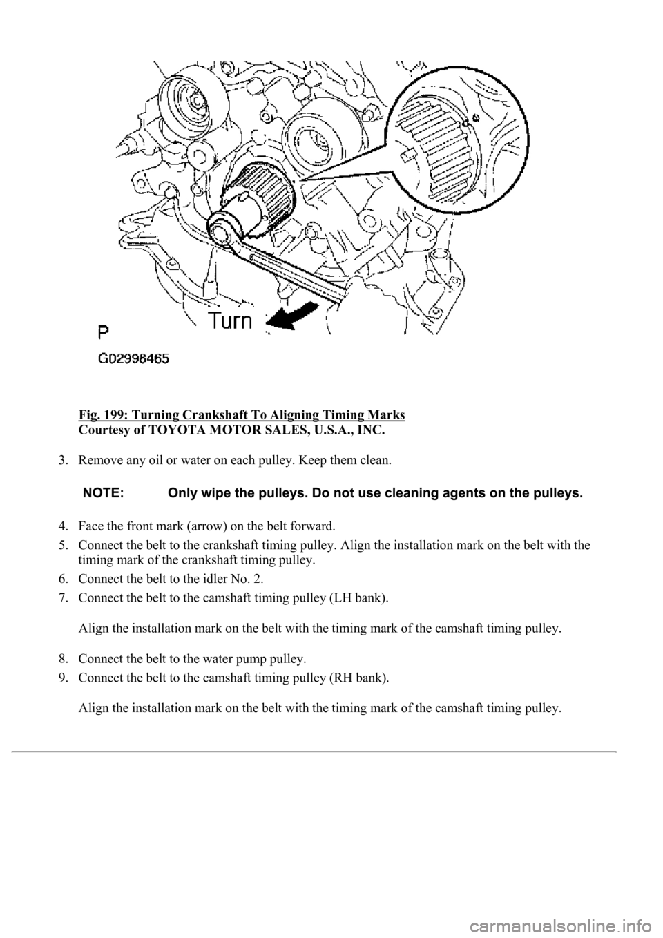
Fig. 199: Turning Crankshaft To Aligning Timing Marks
Courtesy of TOYOTA MOTOR SALES, U.S.A., INC.
3. Remove any oil or water on each pulley. Keep them clean.
4. Face the front mark (arrow) on the belt forward.
5. Connect the belt to the crankshaft timing pulley. Align the installation mark on the belt with the
timing mark of the crankshaft timing pulley.
6. Connect the belt to the idler No. 2.
7. Connect the belt to the camshaft timing pulley (LH bank).
Align the installation mark on the belt with the timing mark of the camshaft timing pulley.
8. Connect the belt to the water pump pulley.
9. Connect the belt to the camshaft timing pulley (RH bank).
Align the installation mark on the belt with the timing mark of the camshaft timing pulley.
Page 3483 of 4500
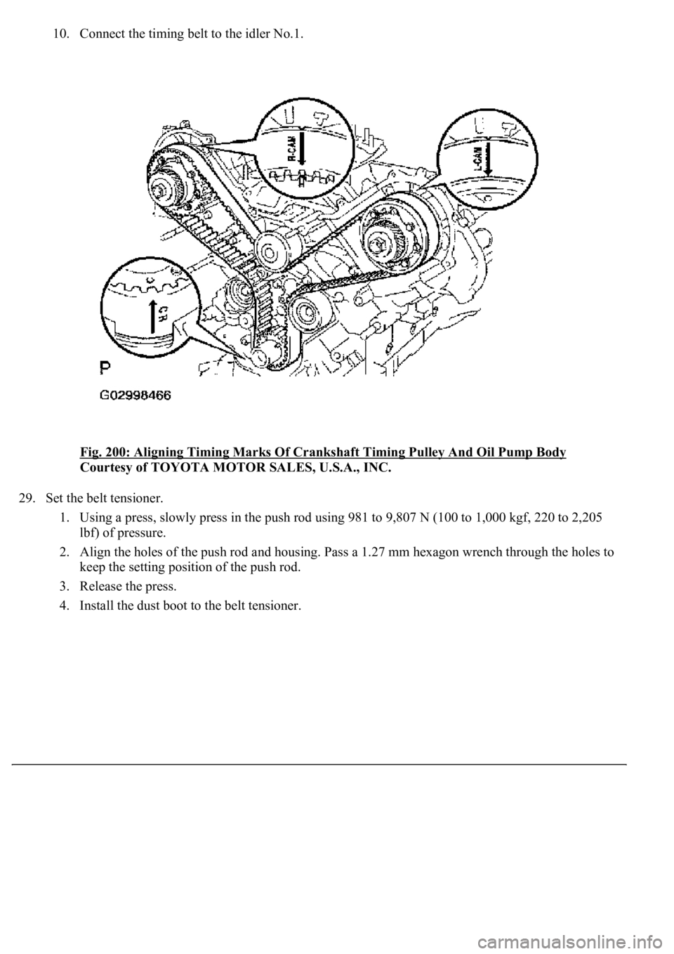
10. Connect the timing belt to the idler No.1.
Fig. 200: Aligning Timing Marks Of Crankshaft Timing Pulley And Oil Pump Body
Courtesy of TOYOTA MOTOR SALES, U.S.A., INC.
29. Set the belt tensioner.
1. Using a press, slowly press in the push rod using 981 to 9,807 N (100 to 1,000 kgf, 220 to 2,205
lbf) of pressure.
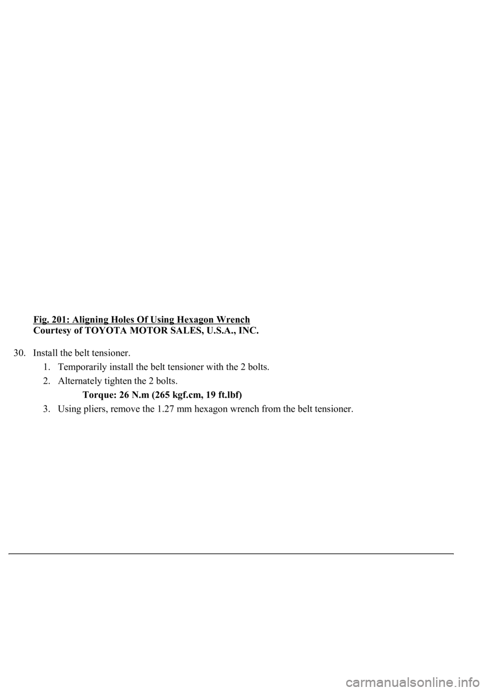
2. Align the holes of the push rod and housing. Pass a 1.27 mm hexagon wrench through the holes to
keep the setting position of the push rod.
3. Release the press.
4. Install the dust boot to the belt tensioner.
Page 3484 of 4500
Fig. 201: Aligning Holes Of Using Hexagon Wrench
Courtesy of TOYOTA MOTOR SALES, U.S.A., INC.
30. Install the belt tensioner.
1. Temporarily install the belt tensioner with the 2 bolts.
2. Alternately tighten the 2 bolts.
Torque: 26 N.m (265 kgf.cm, 19 ft.lbf)
3. Usin
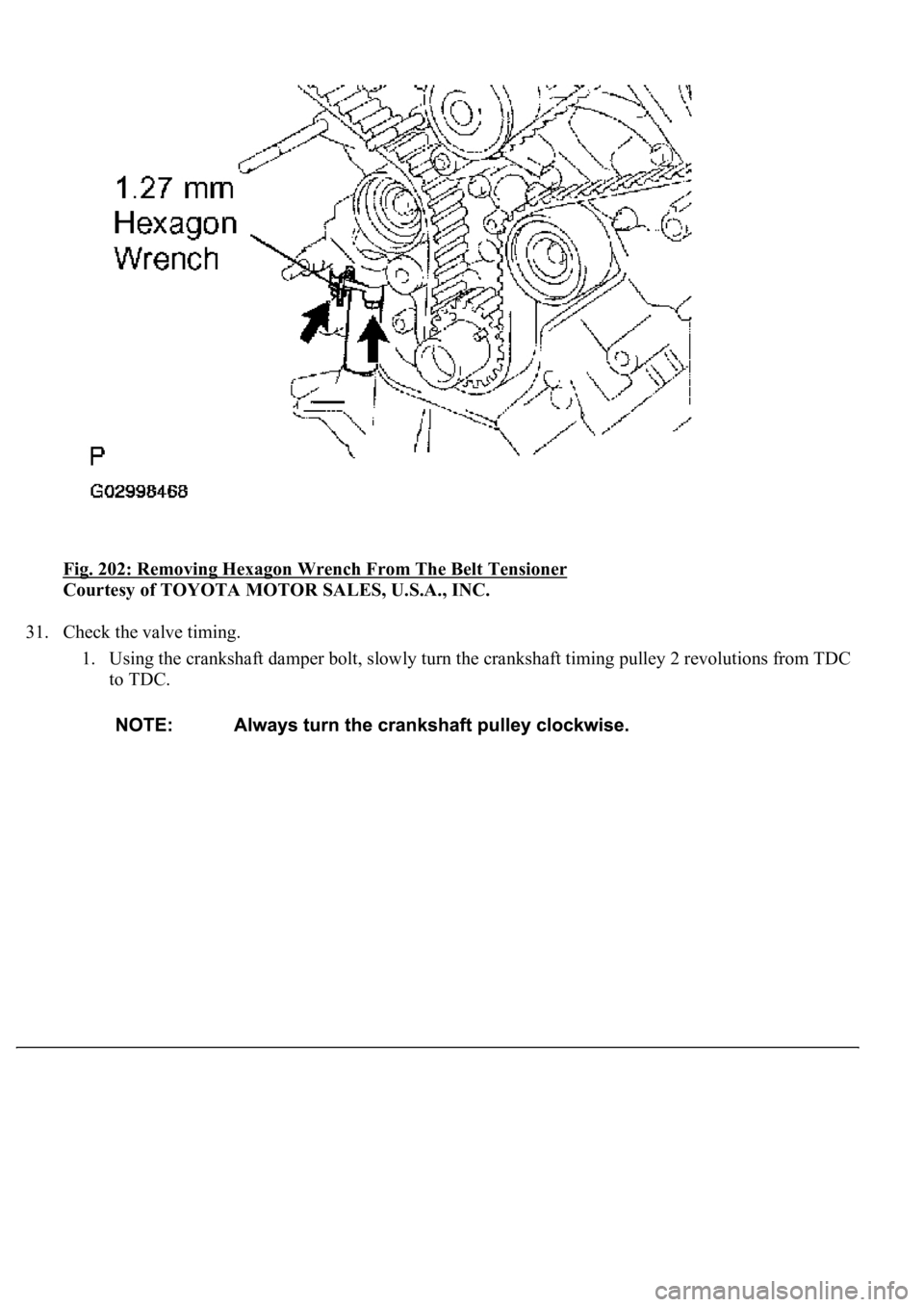
g pliers, remove the 1.27 mm hexagon wrench from the belt tensioner.
Page 3485 of 4500
<0029004c004a00110003001500130015001d000300350048005000520059004c0051004a0003002b0048005b0044004a005200510003003a0055004800510046004b0003002900550052005000030037004b0048000300250048004f005700030037004800
510056004c0052005100480055[
Courtesy of TOYOTA MOTOR SALES, U.S.A., INC.
31. Check the valve timing.
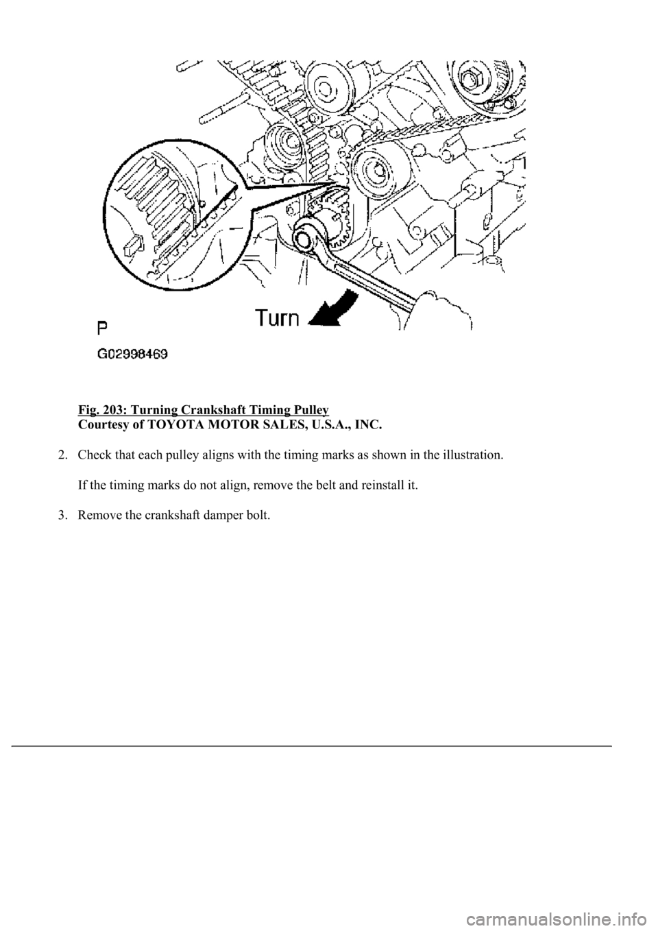
1. Using the crankshaft damper bolt, slowly turn the crankshaft timing pulley 2 revolutions from TDC
to TDC.
Page 3486 of 4500
Fig. 203: Turning Crankshaft Timing Pulley
Courtesy of TOYOTA MOTOR SALES, U.S.A., INC.
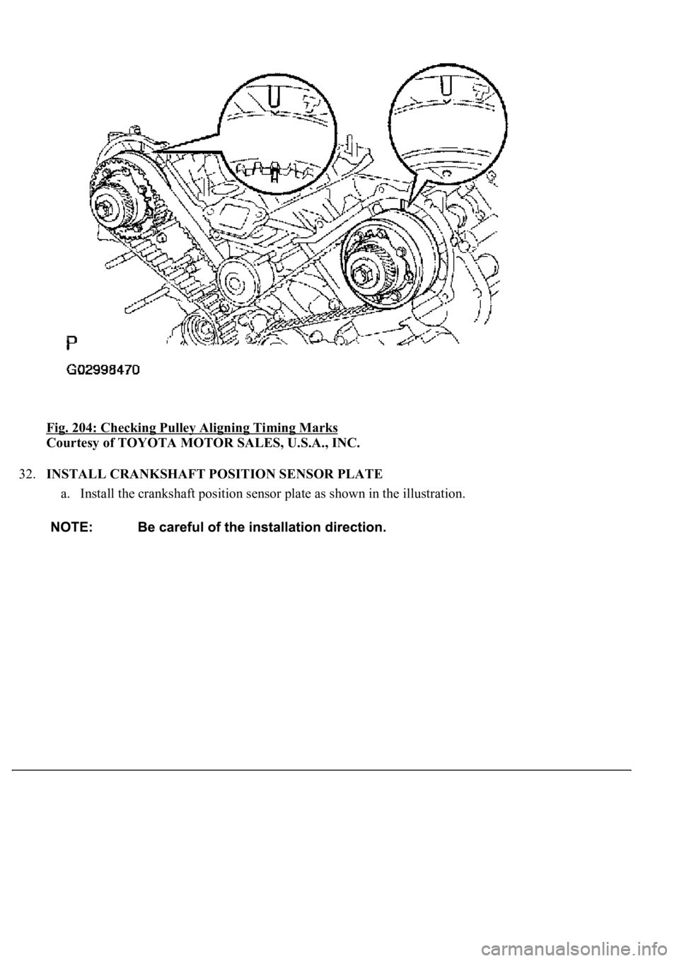
2. Check that each pulley aligns with the timing marks as shown in the illustration.
If the timing marks do not align, remove the belt and reinstall it.
3. Remove the crankshaft damper bolt.
Page 3487 of 4500
Fig. 204: Checking Pulley Aligning Timing Marks
Courtesy of TOYOTA MOTOR SALES, U.S.A., INC.
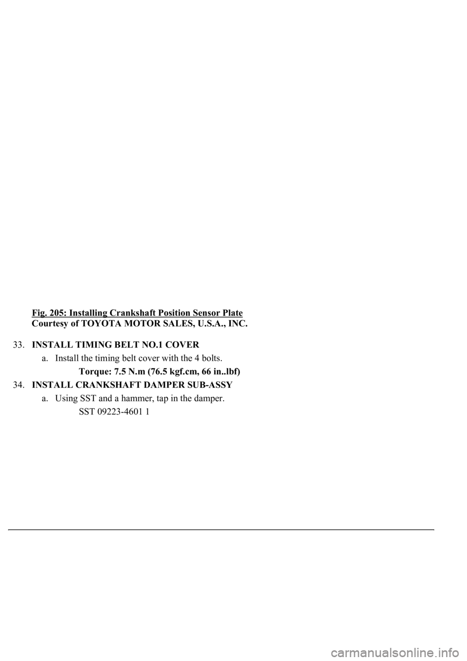
32.INSTALL CRANKSHAFT POSITION SENSOR PLATE
a. Install the crankshaft position sensor plate as shown in the illustration.
Page 3488 of 4500
Fig. 205: Installing Crankshaft Position Sensor Plate
Courtesy of TOYOTA MOTOR SALES, U.S.A., INC.
33.INSTALL TIMING BELT NO.1 COVER
a. Install the timing belt cover with the 4 bolts.
Torque: 7.5 N.m (76.5 kgf.cm, 66 in..lbf)
34.INSTALL CRANKSHAFT DAMPER SUB-ASSY
a. Using SST and a hammer, tap in the damper.
SST 09223-4601 1
Page 3489 of 4500
Fig. 206: Taping Damper Using SST And Hammer
Courtesy of TOYOTA MOTOR SALES, U.S.A., INC.
b. Using SST, install the damper bolt.
SST 09213-7001 1, 09330-00021
Torque: 245 N.m (2,500 kgf.cm, 181 ft.lbf)
c. Ali
gn the pulley set key with the key groove of the crankshaft damper.
Page 3490 of 4500
Fig. 207: Installing Damper Bolt Using SST
Courtesy of TOYOTA MOTOR SALES, U.S.A., INC.
35.INSTALL IDLER PULLEY ASSY
a. Install the idler with the 2 bolts and 2 nuts.
Torque:
32 N.m (326 kgf.cm, 24 ft.lbf) for 14 mm head bolt A
16 N.m (163 kgf.cm, 12 ft.lbf) for 12 mm head bolt B
Trending: automatic transmission fluid, airbag, adding oil, ABS, B2620, Expansion Valve, oil filter
