LEXUS LS430 2003 Factory Repair Manual
Manufacturer: LEXUS, Model Year: 2003,
Model line: LS430,
Model: LEXUS LS430 2003
Pages: 4500, PDF Size: 87.45 MB
LEXUS LS430 2003 Factory Repair Manual
LS430 2003
LEXUS
LEXUS
https://www.carmanualsonline.info/img/36/57050/w960_57050-0.png
LEXUS LS430 2003 Factory Repair Manual
Trending: Conditioner, oil pressure, bluetooth, B2419, vacuum switch, Lock actuator, air filter
Page 4261 of 4500
Fig. 74: Removing Air Inlet Servomotor
Courtesy of TOYOTA MOTOR SALES, U.S.A., INC.
13.REMOVE BLOWER MOTOR ASSY (COOLING UNIT MOTOR SUB-ASSY W/FAN)
a. Remove the 3 screws and blower motor assy (cooling unit motor sub-assy w/fan).
ON-VEHICLE INSPECTION
1.INSPECT COMPRESSOR FOR METALLIC SOUND
a. Check if there is abnormal metallic sound from the compressor when the A/C switch is ON and the
compressor operates.
If abnormal metallic sound is heard, replace the compressor assembly.
2.INSPECT REFRIGERANT PRESSURE (See ON
-VEHICLE INSPECTION )
3.INSPECT FOR LEAKAGE OF REFRIGERANT
Page 4262 of 4500
a. Using a gas leak detector, check for leakage of refrigerant.
<002c004900030057004b0048005500480003004c0056000300440051005c0003004f00480044004e0044004a0048000f0003005500480053004f00440046004800030057004b00480003004600520050005300550048005600560052005500030044005600
56004800500045004f005c00110003[
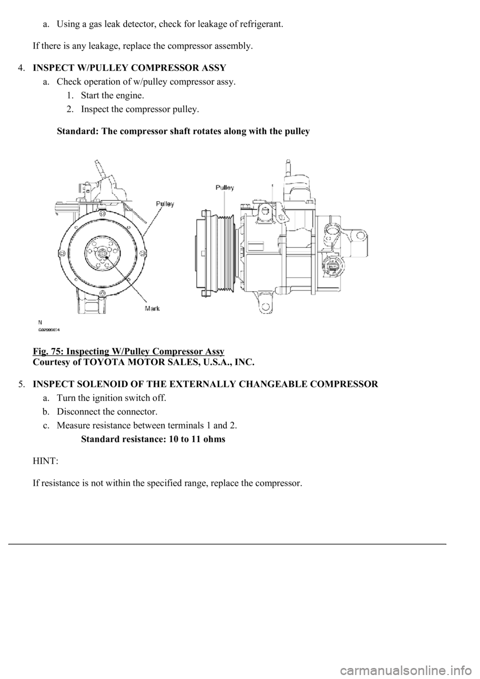
4.INSPECT W/PULLEY COMPRESSOR ASSY
a. Check operation of w/pulley compressor assy.
1. Start the engine.
2. Inspect the compressor pulley.
Standard: The compressor shaft rotates along with the pulley
Fig. 75: Inspecting W/Pulley Compressor Assy
Courtesy of TOYOTA MOTOR SALES, U.S.A., INC.
5.INSPECT SOLENOID OF THE EXTERNALLY CHANGEABLE COMPRESSOR
a. Turn the ignition switch off.
b. Disconnect the connector.
c. Measure resistance between terminals 1 and 2.
Standard resistance: 10 to 11 ohms
HINT:
If resistance is not within the specified ran
ge, replace the compressor.
Page 4263 of 4500
Fig. 76: Inspecting Solenoid Of Externally Changeable Compressor
Courtesy of TOYOTA MOTOR SALES, U.S.A., INC.
REPLACEMENT
1.DISCONNECT NEGATIVE TERMINAL CABLE FROM BATTERY
2.EVACUATE REFRIGERANT HFC-134A (R134A) (See REPLACEMENT
)
3.REMOVE AIR CLEANER INLET NO. 1 (See REPLACEMENT
)
4.REMOVE FAN AND GENERATOR V BELT (See REPLACEMENT
)
5.REMOVE ENGINE UNDER COVER NO. 1
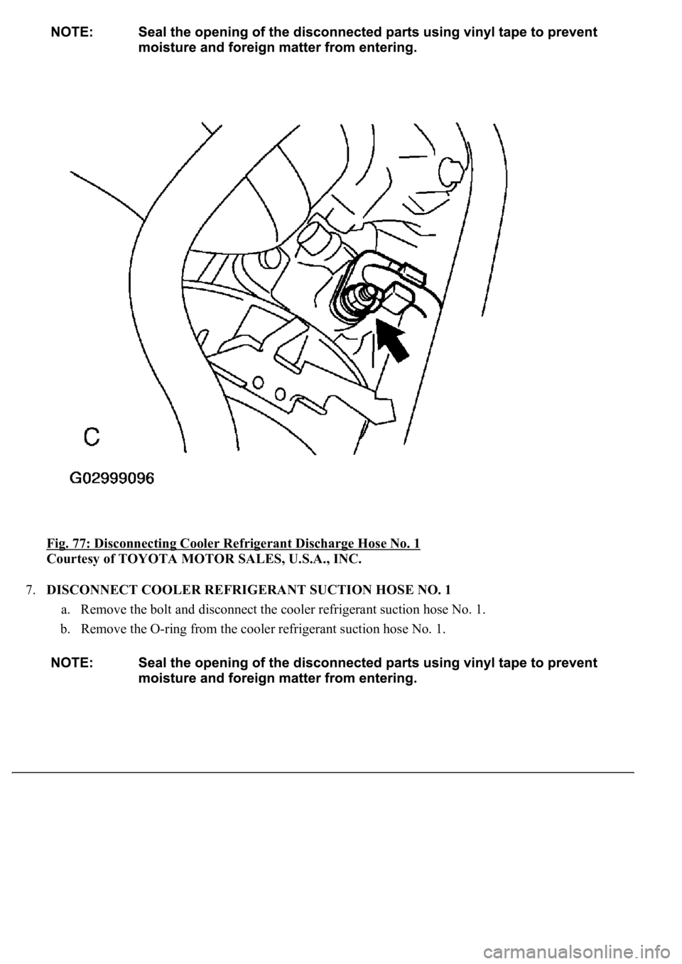
6.DISCONNECT COOLER REFRIGERANT DISCHARGE HOSE NO. 1
a. Remove the nut and disconnect the cooler refrigerant discharge hose No. 1.
b. Remove the O-ring from the cooler refrigerant discharge hose No. 1.
Page 4264 of 4500
Fig. 77: Disconnecting Cooler Refrigerant Discharge Hose No. 1
Courtesy of TOYOTA MOTOR SALES, U.S.A., INC.
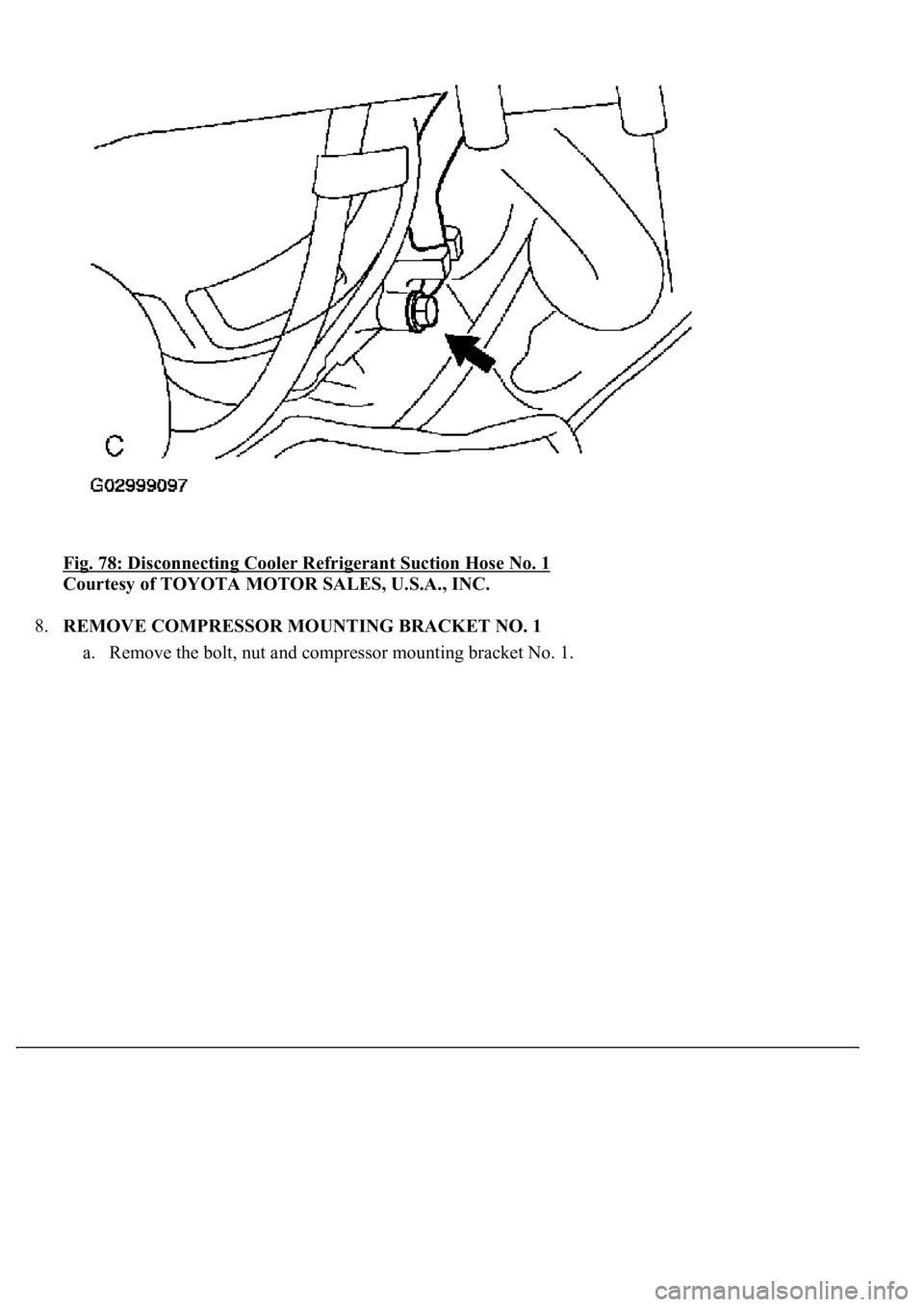
7.DISCONNECT COOLER REFRIGERANT SUCTION HOSE NO. 1
a. Remove the bolt and disconnect the cooler refrigerant suction hose No. 1.
b. Remove the O-ring from the cooler refrigerant suction hose No. 1.
Page 4265 of 4500
<0029004c004a00110003001a001b001d00030027004c00560046005200510051004800460057004c0051004a0003002600520052004f0048005500030035004800490055004c004a0048005500440051005700030036005800460057004c00520051000300
2b005200560048000300310052001100030014[
Courtesy of TOYOTA MOTOR SALES, U.S.A., INC.
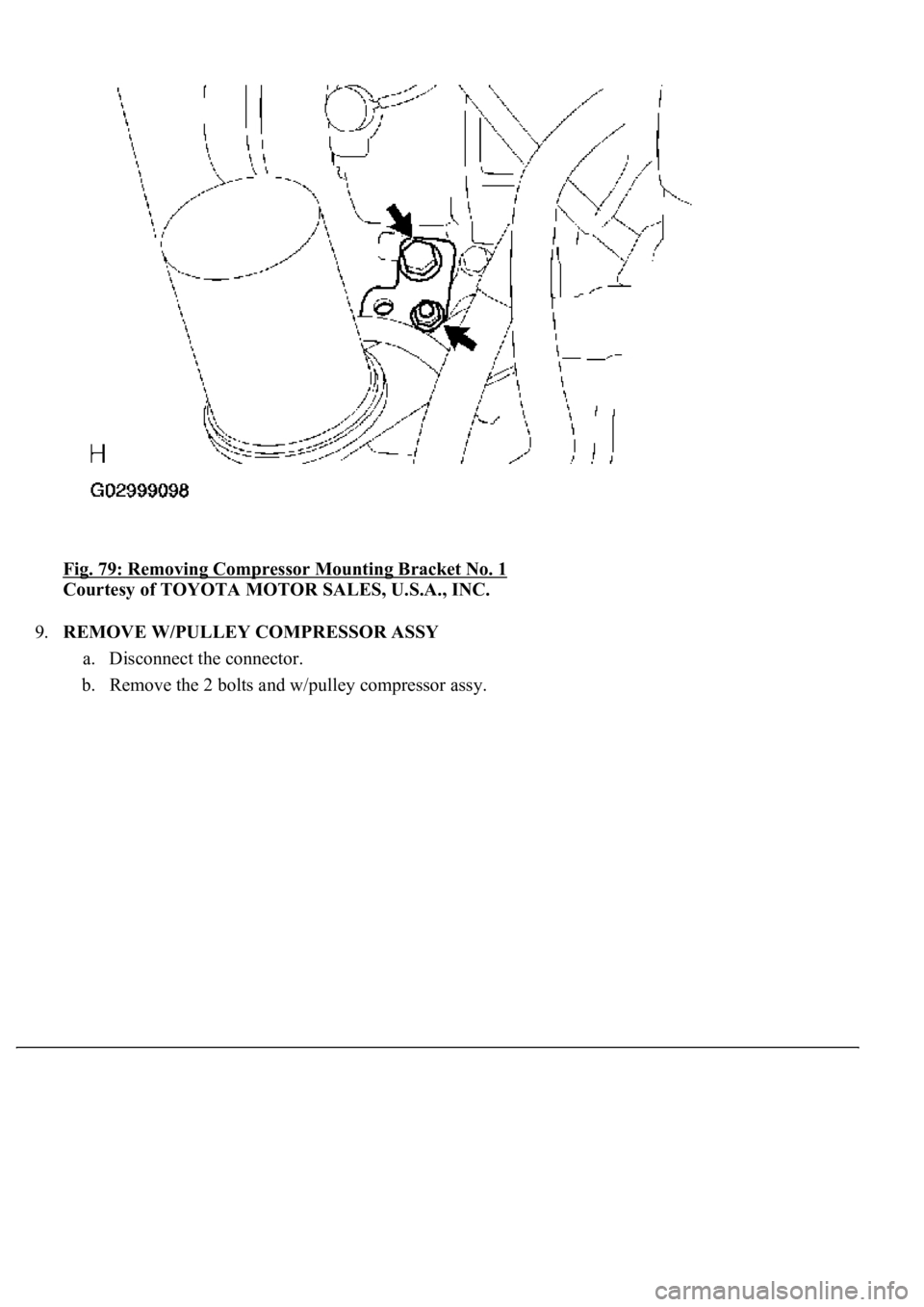
8.REMOVE COMPRESSOR MOUNTING BRACKET NO. 1
a. Remove the bolt, nut and compressor mounting bracket No. 1.
Page 4266 of 4500
<0029004c004a00110003001a001c001d000300350048005000520059004c0051004a00030026005200500053005500480056005600520055000300300052005800510057004c0051004a00030025005500440046004e004800570003003100520011000300
14[
Courtesy of TOYOTA MOTOR SALES, U.S.A., INC.
9.REMOVE W/PULLEY COMPRESSOR ASSY
a. Disconnect the connector.
b. Remove the 2 bolts and w/pulley compressor assy.
Page 4267 of 4500
Fig. 80: Removing W/Pulley Compressor Assy
Courtesy of TOYOTA MOTOR SALES, U.S.A., INC.
10.ADJUST COMPRESSOR OIL
a. When replacing the compressor and magnetic clutch with a new one, after gradually removing the
refrigerant gas from the service valve, drain the following amount of oil from the new compressor
and magnetic clutch before installation.
Standard:
(Oil capacity inside the new compressor: 130 +15 cc (4.4 +0.5 fl.oz)) - (Remaining oil
amount in the removed compressor) = (Oil amount to be removed from the new
compressor when replacing)
Page 4268 of 4500
11.TEMPORARILY TIGHTEN W/PULLEY COMPRESSOR ASSY
a. Temporarily tighten the w/pulley compressor assy with the 2 bolts.
b. Connect the connector.
Fig. 81: Tightening W/Pulley Compressor Assy Bolts Temporarily
Courtesy of TOYOTA MOTOR SALES, U.S.A., INC.
12.INSTALL COMPRESSOR MOUNTING BRACKET NO. 1
a. Install the compressor mounting bracket No. 1 with the bolt and nut.
Torque:
Bolt: 49 N.m (500 kgf.cm, 36ft.lbf)
Nut: 30 N.m (306 kgf.cm, 22 ft.lbf)
Page 4269 of 4500
Fig. 82: Installing Compressor Mounting Bracket No. 1
Courtesy of TOYOTA MOTOR SALES, U.S.A., INC.
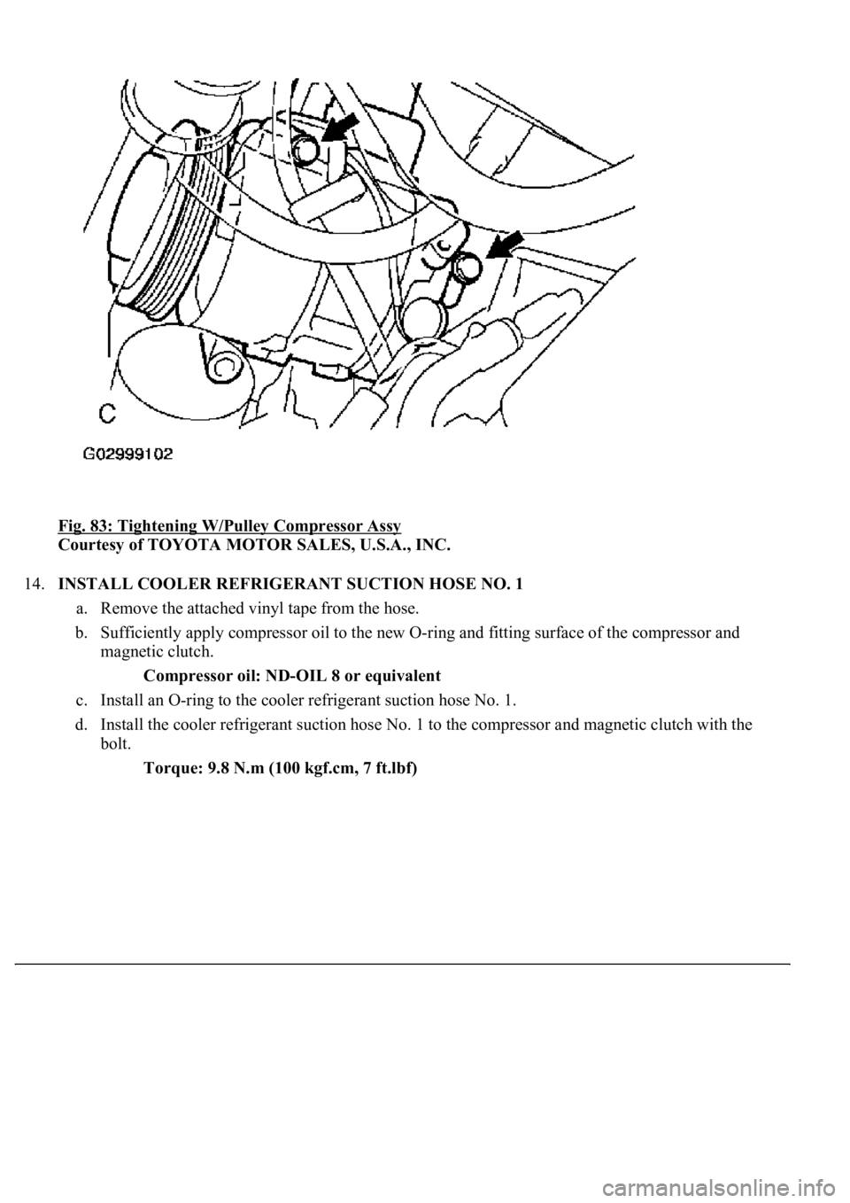
13.FULLY TIGHTEN W/PULLEY COMPRESSOR ASSY
a. Fully tighten the w/pulley compressor assy with the 2 bolts.
Torque: 49 N.m (500 kgf.cm, 36 ft.lbf)
Page 4270 of 4500
Fig. 83: Tightening W/Pulley Compressor Assy
Courtesy of TOYOTA MOTOR SALES, U.S.A., INC.
14.INSTALL COOLER REFRIGERANT SUCTION HOSE NO. 1
a. Remove the attached vinyl tape from the hose.
b. Sufficiently apply compressor oil to the new O-ring and fitting surface of the compressor and
magnetic clutch.
Compressor oil: ND-OIL 8 or equivalent
c. Install an O-ring to the cooler refrigerant suction hose No. 1.
d. Install the cooler refrigerant suction hose No. 1 to the compressor and magnetic clutch with the
bolt.
Torque: 9.8 N.m (100 kgf.cm, 7 ft.lbf)
Trending: adding oil, Spark plug firing order, oil change, content, coolant reservoir, steering wheel adjustment, key
