LEXUS LS430 2003 Factory Repair Manual
Manufacturer: LEXUS, Model Year: 2003,
Model line: LS430,
Model: LEXUS LS430 2003
Pages: 4500, PDF Size: 87.45 MB
LEXUS LS430 2003 Factory Repair Manual
LS430 2003
LEXUS
LEXUS
https://www.carmanualsonline.info/img/36/57050/w960_57050-0.png
LEXUS LS430 2003 Factory Repair Manual
Trending: wheel size, horn, Navi, content, lane assist, zero point calibration, lumbar support
Page 4241 of 4500
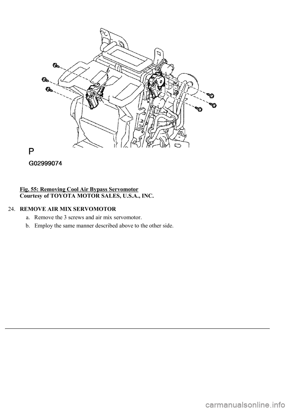
Fig. 55: Removing Cool Air Bypass Servomotor
Courtesy of TOYOTA MOTOR SALES, U.S.A., INC.
24.REMOVE AIR MIX SERVOMOTOR
a. Remove the 3 screws and air mix servomotor.
b. Employ the same manner described above to the other side.
Page 4242 of 4500
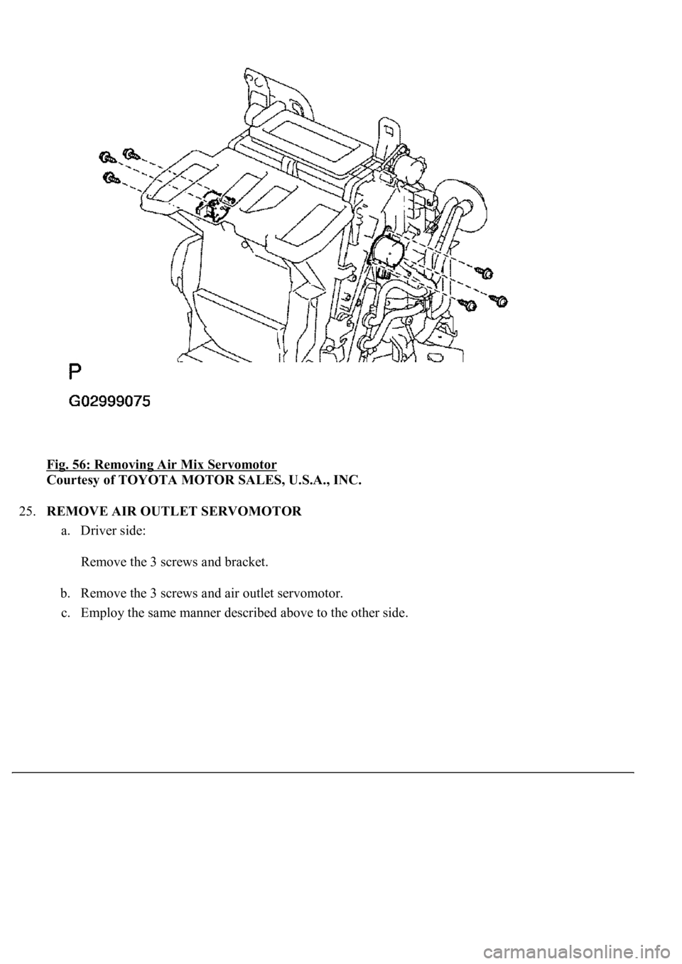
Fig. 56: Removing Air Mix Servomotor
Courtesy of TOYOTA MOTOR SALES, U.S.A., INC.
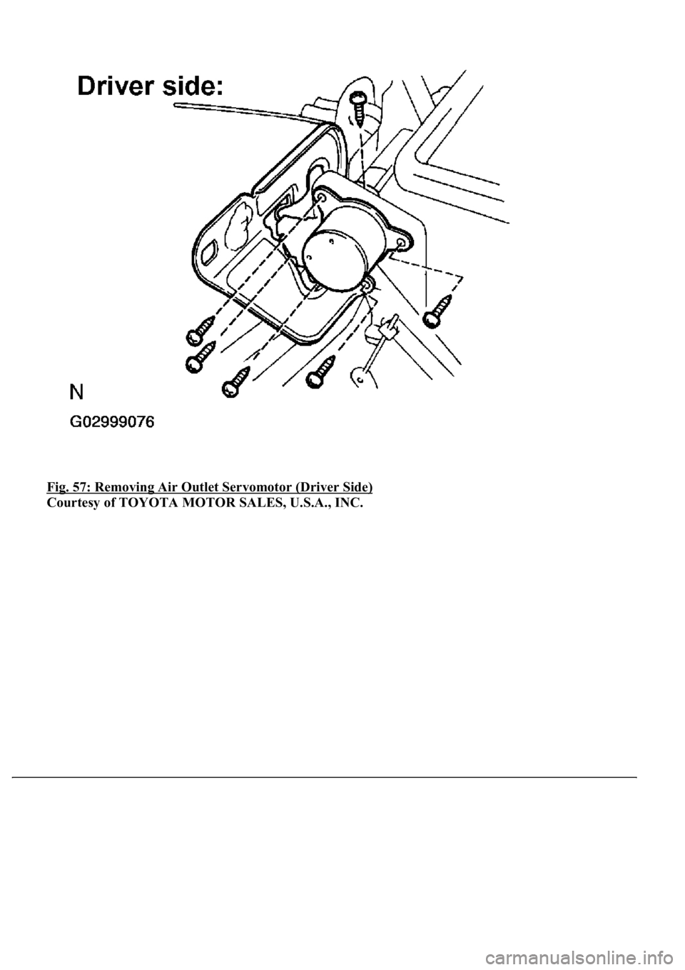
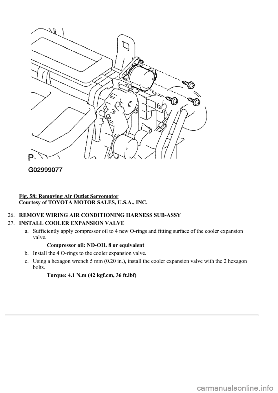
25.REMOVE AIR OUTLET SERVOMOTOR
a. Driver side:
Remove the 3 screws and bracket.
b. Remove the 3 screws and air outlet servomotor.
c. Emplo
y the same manner described above to the other side.
Page 4243 of 4500
Fig. 57: Removing Air Outlet Servomotor (Driver Side)
Courtesy of TOYOTA MOTOR SALES, U.S.A., INC.
Page 4244 of 4500
Fig. 58: Removing Air Outlet Servomotor
Courtesy of TOYOTA MOTOR SALES, U.S.A., INC.
26.REMOVE WIRING AIR CONDITIONING HARNESS SUB-ASSY
27.INSTALL COOLER EXPANSION VALVE
a. Sufficiently apply compressor oil to 4 new O-rings and fitting surface of the cooler expansion
valve.
Compressor oil: ND-OIL 8 or equivalent
b. Install the 4 O-rings to the cooler expansion valve.
c. Using a hexagon wrench 5 mm (0.20 in.), install the cooler expansion valve with the 2 hexagon
bolts.
Torque: 4.1 N.m (42 kgf.cm, 36 ft.lbf)
Page 4245 of 4500
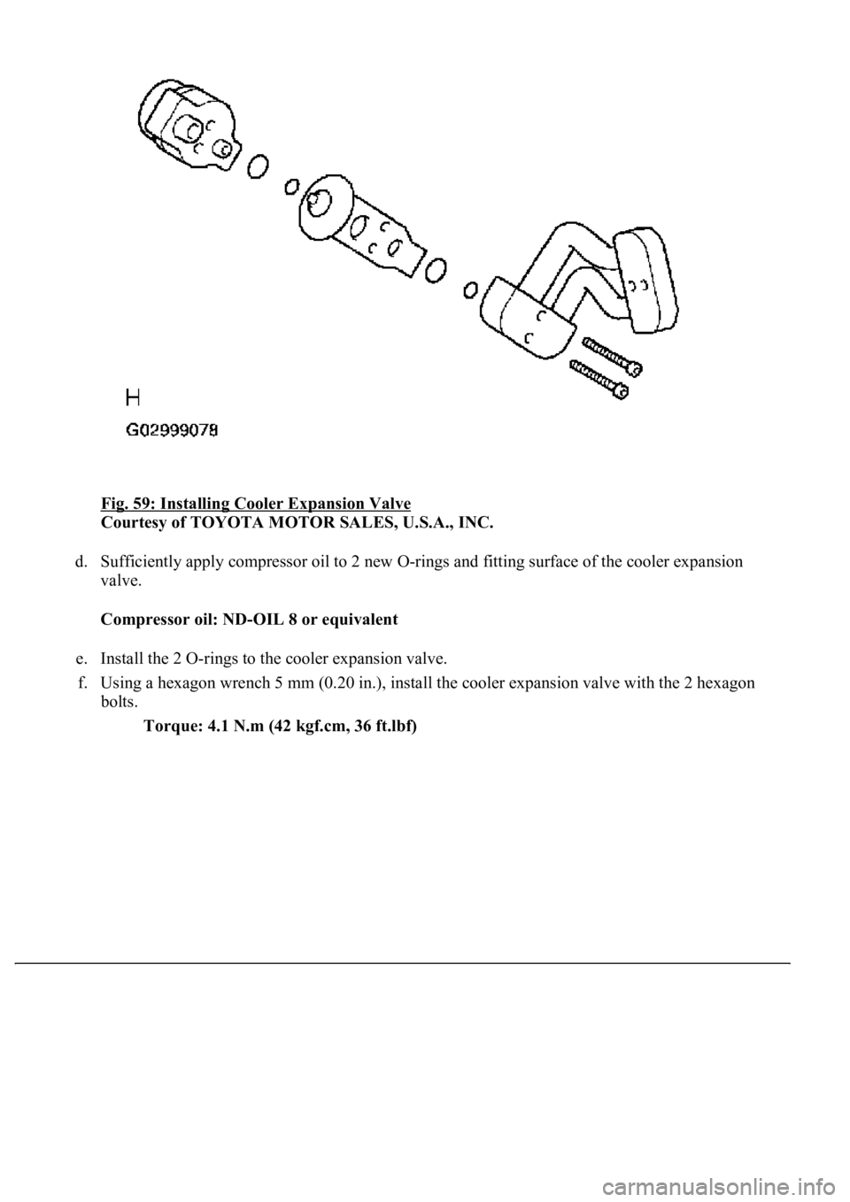
Fig. 59: Installing Cooler Expansion Valve
Courtesy of TOYOTA MOTOR SALES, U.S.A., INC.
d. Sufficiently apply compressor oil to 2 new O-rings and fitting surface of the cooler expansion
valve.
Compressor oil: ND-OIL 8 or equivalent
e. Install the 2 O-rings to the cooler expansion valve.
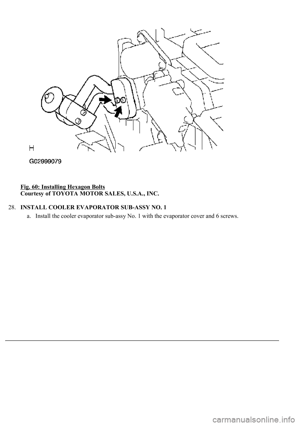
f. Using a hexagon wrench 5 mm (0.20 in.), install the cooler expansion valve with the 2 hexagon
bolts.
Torque: 4.1 N.m (42 kgf.cm, 36 ft.lbf)
Page 4246 of 4500
Fig. 60: Installing Hexagon Bolts
Courtesy of TOYOTA MOTOR SALES, U.S.A., INC.
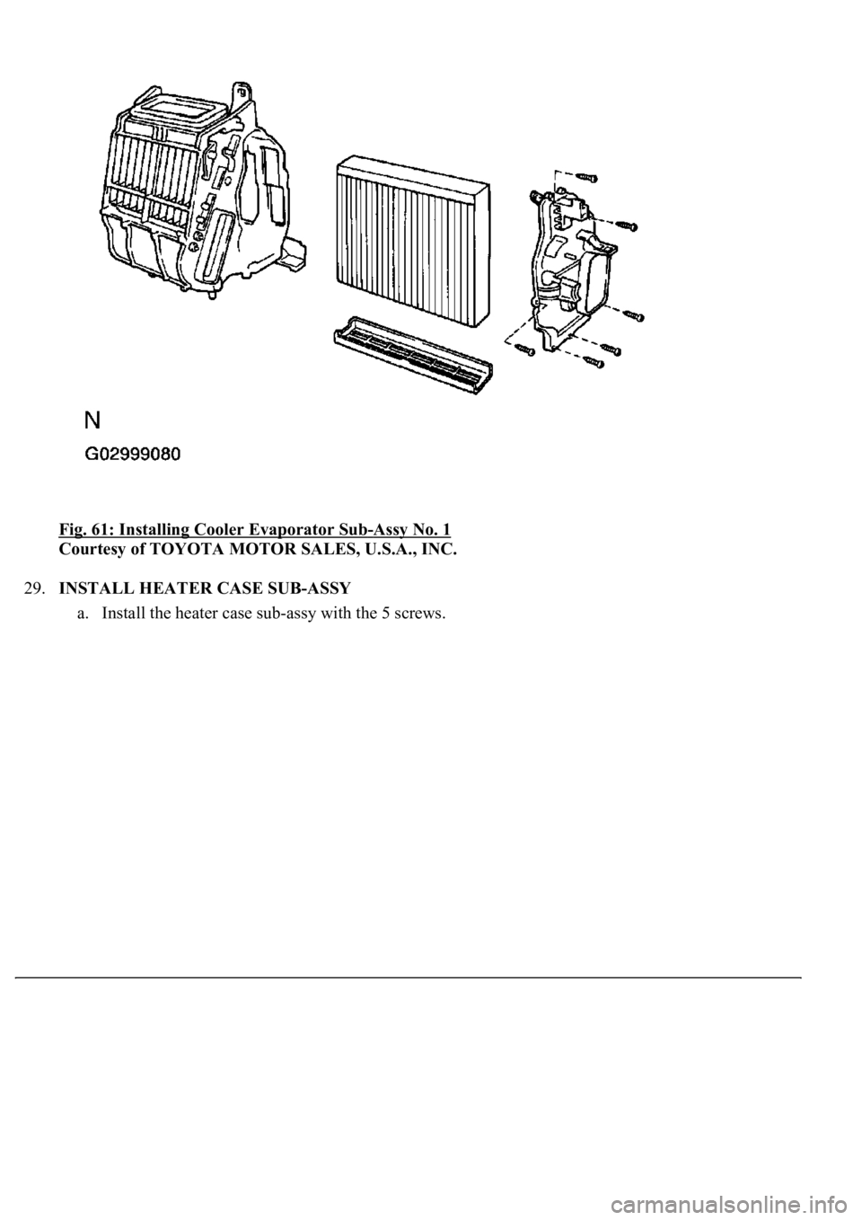
28.INSTALL COOLER EVAPORATOR SUB-ASSY NO. 1
a. Install the cooler evaporator sub-ass
y No. 1 with the evaporator cover and 6 screws.
Page 4247 of 4500
Fig. 61: Installing Cooler Evaporator Sub-Assy No. 1
Courtesy of TOYOTA MOTOR SALES, U.S.A., INC.
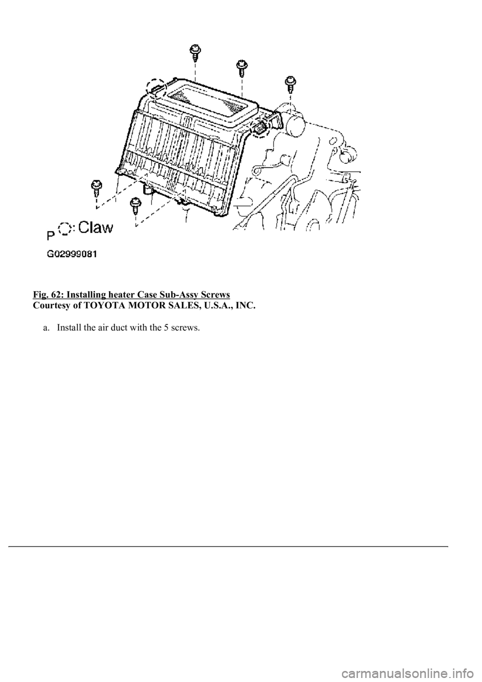
29.INSTALL HEATER CASE SUB-ASSY
a. Install the heater case sub-ass
y with the 5 screws.
Page 4248 of 4500
Fig. 62: Installing heater Case Sub-Assy Screws
Courtesy of TOYOTA MOTOR SALES, U.S.A., INC.
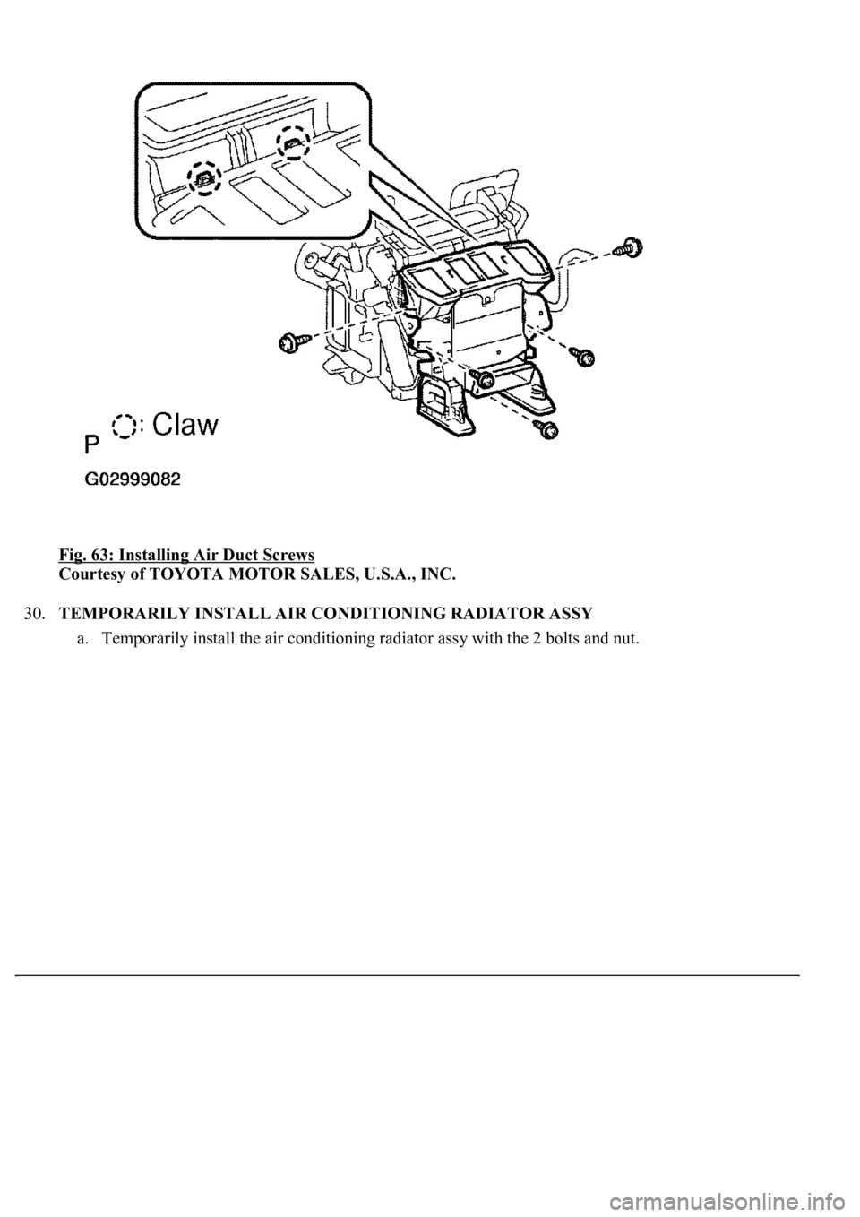
a. Install the air duct with the 5 screws.
Page 4249 of 4500
Fig. 63: Installing Air Duct Screws
Courtesy of TOYOTA MOTOR SALES, U.S.A., INC.
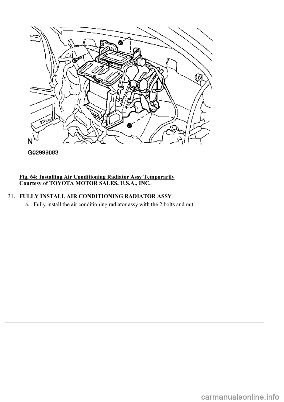
30.TEMPORARILY INSTALL AIR CONDITIONING RADIATOR ASSY
a. Temporarily install the air conditioning radiator assy with the 2 bolts and nut.
Page 4250 of 4500
Fig. 64: Installing Air Conditioning Radiator Assy Temporarily
Courtesy of TOYOTA MOTOR SALES, U.S.A., INC.
31.FULLY INSTALL AIR CONDITIONING RADIATOR ASSY
a. Full
y install the air conditioning radiator assy with the 2 bolts and nut.
Trending: roof rack, key battery, warning, snow chains, Navi, Diagram ac amplifier, Speedometer
