MAZDA 626 1987 Workshop Manual
Manufacturer: MAZDA, Model Year: 1987, Model line: 626, Model: MAZDA 626 1987Pages: 1865, PDF Size: 94.35 MB
Page 531 of 1865
AIR INJECTION SYSTEM 4B
TROUBLESHOOTING
Check the condition of the wiring harness and connectors before checking the sensors or switch.
Note
Make the system inspection first. If no problem is found, continue with the next system
inspection of the Troubleshooting Guide. (Refer to pages 4B—7 and 8.)
Possible cause Air control valve Reed valve System inspection
Page 4B—69 4B—70 4B—69
Checking order 2 3 1
76G04B-097
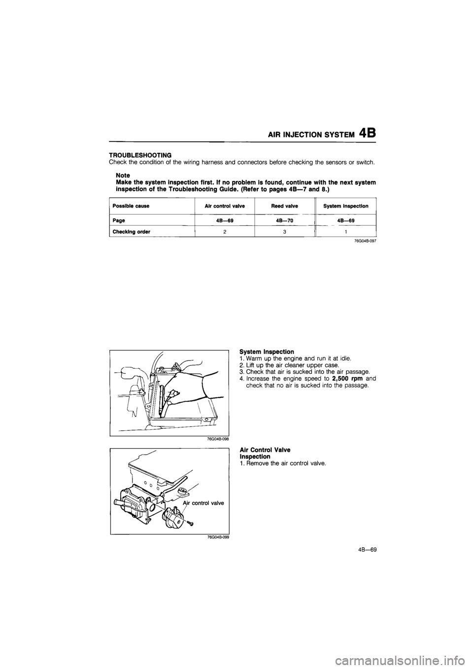
System Inspection
1. Warm up the engine and run it at idle.
2. Lift up the air cleaner upper case.
3. Check that air is sucked into the air passage.
4. Increase the engine speed to 2,500 rpm and
check that no air is sucked into the passage.
Air Control Valve
Inspection
1. Remove the air control valve.
4B-69
Page 532 of 1865
4B AIR INJECTION SYSTEM
56G04B-114p
76G04B-100
76U04A-066
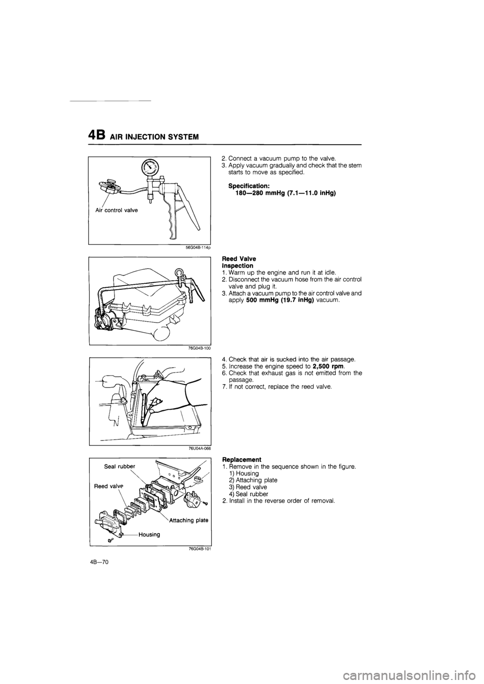
2. Connect a vacuum pump to the valve.
3. Apply vacuum gradually and check that the stem
starts to move as specified.
Specification:
180—280 mmHg (7.1—11.0 inHg)
Reed Valve
Inspection
1. Warm up the engine and run it at idle.
2. Disconnect the vacuum hose from the air control
valve and plug it.
3. Attach a vacuum pump to the air control valve and
apply 500 mmHg (19.7 inHg) vacuum.
4. Check that air is sucked into the air passage.
5. Increase the engine speed to 2,500 rpm.
6. Check that exhaust gas is not emitted from the
passage.
7. If not correct, replace the reed valve.
Replacement
1. Remove in the sequence shown in the figure.
1) Housing
2) Attaching plate
3) Reed valve
4) Seal rubber
2. Install in the reverse order of removal.
76G04B-101
4B—70
Page 533 of 1865

EGR SYSTEM 4B
EXHAUST GAS RECIRCULATION
(EGR)
SYSTEM
EGR modulator valve Solenoid valve (EGR)
86U04A-127
This system introduces exhaust gas into the intake manifold to reduce NOx in the exhaust gas. It oper-
ates depending on the engine load, engine speed (above 1,500 rpm), engine coolant temperature
(above 70°C, 158°F), and radiator coolant temperature (above 17°C, 63°F).
COMPONENT DESCRIPTIONS
Component Function Remarks
EGR control valve Recirculates portion of exhaust gas
EGR modulator valve Controls vacuum acting on EGR control
valve
Engine control unit Detects signals from input sensors and switches; controls solenoid valve (EGR)
Ignition coil (-) terminal Detects engine speed; sends signal to engine control unit
Solenoid valve (EGR) Controls vacuum line to EGR control
valve
Throttle sensor Detects throttle valve opening angle; sends signal to engine control unit Integrated idle switch
Water thermo sensor Detects coolant temperature; sends signal to engine control unit
Water thermo switch Detects radiator coolant temperature; sends signal to engine control unit
ON: above 17°C (63°F)
76G04B-102
4B-71
Page 534 of 1865
4B EGR SYSTEM
TROUBLESHOOTING
Check the condition of the wiring harness and connectors before checking the sensors or switches below.
Note
Make the system inspection first. If no problem is found, continue with the next system
inspection of the Troubleshooting Guide. (Refer to pages 4B—7 and 8.)
Possible cause
Solenoid
valve (EGR)
EGR modula-tor valve
EGR con-trol valve
Water
thermo sensor
Water
thermo switch
Engine control unit
terminal
System in-spection
2N
Page 4B—72 4B—73 4B—73 4B—97 4B—97 4B—90 4B—72
Checking order 3 2 4 6 5 7 1
76G04B-103
86U04A-130
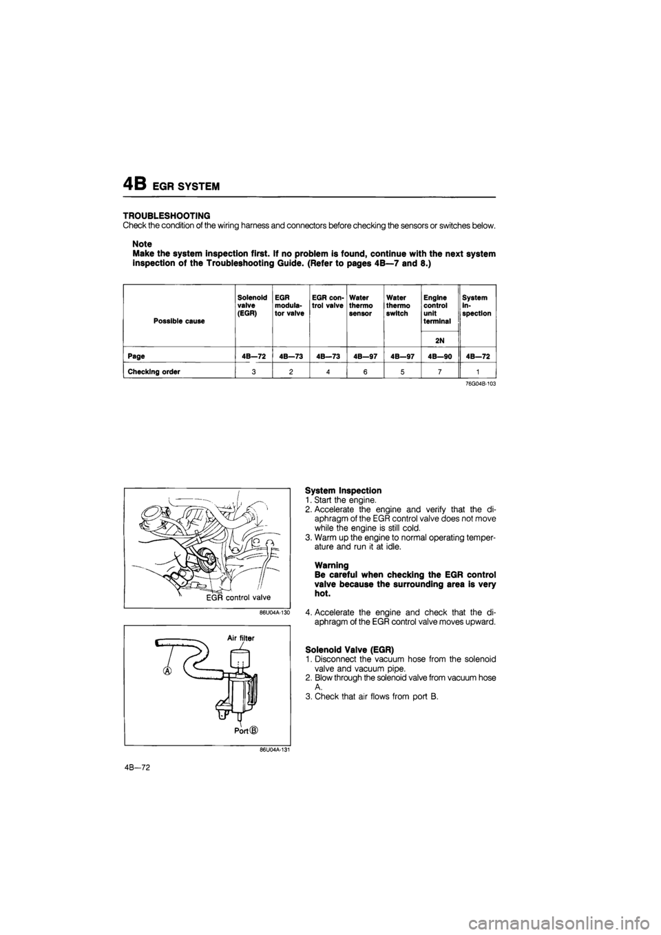
System Inspection
1. Start the engine.
2. Accelerate the engine and verify that the di-
aphragm of the EGR control valve does not move
while the engine is still cold.
3. Warm up the engine to normal operating temper-
ature and run it at idle.
Warning
Be careful when checking the EGR control
valve because the surrounding area is very
hot.
4. Accelerate the engine and check that the di-
aphragm of the EGR control valve moves upward.
Solenoid Valve (EGR)
1. Disconnect the vacuum hose from the solenoid
valve and vacuum pipe.
2. Blow through the solenoid valve from vacuum hose
A.
3. Check that air flows from port B.
86U04A-131
4B-72
Page 535 of 1865
EGR SYSTEM 4B
Apply 12V
Air filter
L
Jt Port
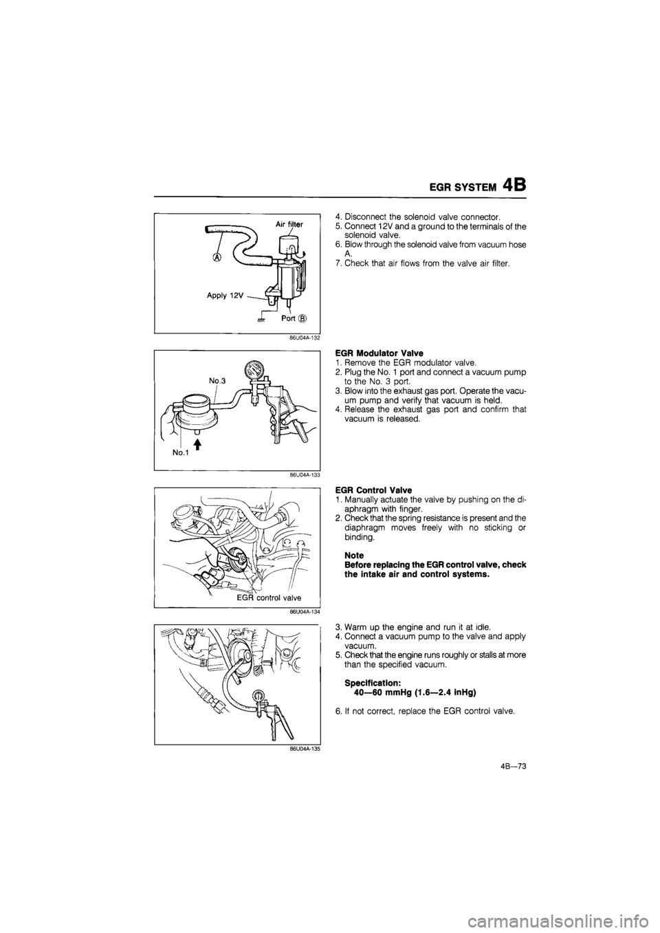
4. Disconnect the solenoid valve connector.
5. Connect 12V and a ground to the terminals of the
solenoid valve.
6. Blow through the solenoid valve from vacuum hose
A.
7. Check that air flows from the valve air filter.
86U04A-132
86U04A-133
86U04A-134
EGR Modulator Valve
1. Remove the EGR modulator valve.
2. Plug the No. 1 port and connect a vacuum pump
to the No. 3 port.
3. Blow into the exhaust gas port. Operate the vacu-
um pump and verify that vacuum is held.
4. Release the exhaust gas port and confirm that
vacuum is released.
EGR Control Valve
1. Manually actuate the valve by pushing on the di-
aphragm with finger.
2. Check that the spring resistance is present and the
diaphragm moves freely with no sticking or
binding.
Note
Before replacing the EGR control valve, check
the intake air and control systems.
3. Warm up the engine and run it at idle.
4. Connect a vacuum pump to the valve and apply
vacuum.
5. Check that the engine runs roughly or stalls at more
than the specified vacuum.
Specification:
40—60 mmHg (1.6—2.4 inHg)
6. If not correct, replace the EGR control valve.
86U04A-135
4B-73
Page 536 of 1865
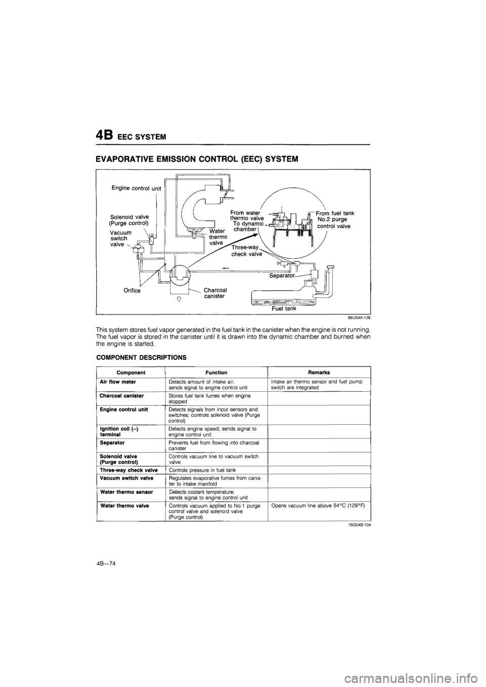
4B EEC SYSTEM
EVAPORATIVE EMISSION CONTROL
(EEC)
SYSTEM
Engine control unit
Solenoid valve
(Purge control)
Vacuum
switch
valve x
From water thermo valve To dynamic -chamber
Three-way
check valve
Orifice Charcoal
canister
From fuel tank
No.2 purge
control valve
Fuel tank
86U04A-136
This system stores fuel vapor generated in the fuel tank in the canister when the engine is not running.
The fuel vapor is stored in the canister until it is drawn into the dynamic chamber and burned when
the engine is started.
COMPONENT DESCRIPTIONS
Component Function Remarks
Air flow meter Detects amount of intake air; sends signal to engine control unit
Intake air thermo sensor and fuel pump
switch are integrated
Charcoal canister Stores fuel tank fumes when engine
stopped
Engine control unit Detects signals from input sensors and switches; controls solenoid valve (Purge control)
Ignition coil (-)
terminal Detects engine speed; sends signal to
engine control unit
Separator Prevents fuel from flowing into charcoal canister
Solenoid valve (Purge control) Controls vacuum line to vacuum switch valve
Three-way check valve Controls pressure in fuel tank
Vacuum switch valve Regulates evaporative fumes from canis-
ter to intake manifold
Water thermo sensor Detects coolant temperature; sends signal to engine control unit
Water thermo valve Controls vacuum applied to No.1 purge control valve and solenoid valve (Purge control)
Opens vacuum line above 54°C (129°F)
76G04B-104
4B—74
Page 537 of 1865
EEC SYSTEM
4B
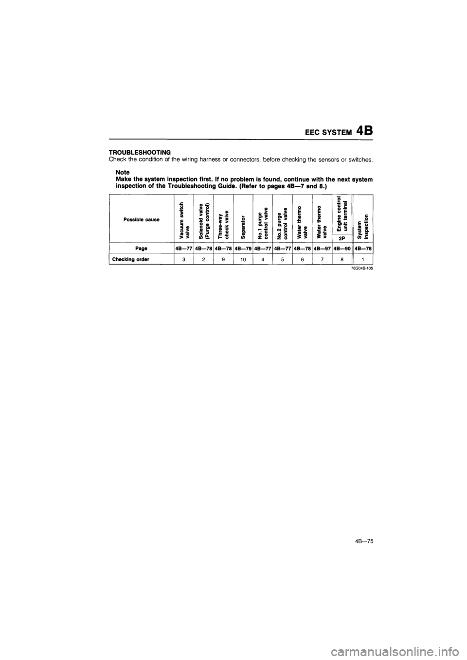
TROUBLESHOOTING
Check
the
condition
of the
wiring harness
or
connectors, before checking
the
sensors
or
switches.
Note
Make the system inspection first.
If no
problem
is
found, continue with
the
next system
inspection
of the
Troubleshooting Guide. (Refer
to
pages 4B—7 and
8.)
Possible cause
Vacuum
switch
valve
Solenoid
valve
(Purge
control)
0)
<0
m
i
>
« «
o
•C
?
o ** «0 a a
No.1
purge
control
valve
No.2
purge
control
valve
Water
thermo
valve
o E tm 0) £
«>
0)
^
>
Engine
control
unit
terminal
System inspection Vacuum
switch
valve
Solenoid
valve
(Purge
control)
purge
control
valve
No.2
purge
control
valve
Water
thermo
valve
$
>
2P
System inspection
Page 4B—77 4B—78 4B—78 4B—79 4B—77 4B—77 4B—78 4B—97 4B—90 4B—76
Checking order 3 2 9 10 4 5 6 7 8 1
76G04B-105
4B—75
Page 538 of 1865
4B EEC SYSTEM
86U04A-139
86U04A-141
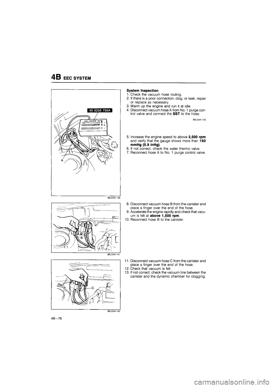
System Inspection
1. Check the vacuum hose routing.
2. If there is a poor connection, clog, or leak, repair
or replace as necessary.
3. Warm up the engine and run it at idle.
4. Disconnect vacuum hose A from No.
1
purge con-
trol valve and connect the SST to the hose.
86 U 04 A-140
5. Increase the engine speed to above 2,500 rpm
and verify that the gauge shows more than 150
mmHg (5.9 inHg).
6. If not correct, check the water thermo valve.
7. Reconnect hose A to No. 1 purge control valve.
8. Disconnect vacuum hose B from the canister and
place a finger over the end of the hose.
9. Accelerate the engine rapidly and check that vacu-
um is felt at above 1,500 rpm.
10. Reconnect hose B to the canister.
11. Disconnect vacuum hose C from the canister and
place a finger over the end of the hose.
12. Check that vacuum is felt.
13. If not correct, check the vacuum line between the
canister and the dynamic chamber for clogging.
86U04A-142
4B—76
Page 539 of 1865

EEC SYSTEM 4B
86U04A-143
86 U 04 A-144
86U04A-145
14. Disconnect the evaporation hose from the evapo-
ration pipe.
15. Connect the vacuum pump to the evaporation
pipe.
16. Operate the vacuum pump and verify that no vacu-
um is held.
17. If vacuum is held, check the evaporation pipe for
clogging.
No. 1 Purge Control Valve
1. Blow through the purge control valve from port A
and check that air does not flow.
2. Connect a vacuum pump to the purge control
valve.
3. Apply 110 mmHg (4.33 inHg) vacuum, and blow
through port A again; air should flow.
No. 2 Purge Control Valve
1. Disconnect vacuum hose B from the evaporation
pipe.
2. Blow through the hose and verify that air flows
freely.
Vacuum Switch Valve
1. Remove vacuum switch valve.
2. Connect a vacuum pump to the valve.
3. Blow through the valve from port A and verify that
air comes out of port B when vacuum is applied.
Specified vacuum:
66—106 mmHg (2.6—4.2 inHg)
86U04A-146
4B-77
Page 540 of 1865

4B EEC SYSTEM
Water Thermo Valve
1. Remove the water thermo valve.
2. Immerse the valve in a water-filled container.
3. Heat the water gradually and observe the tem-
perature.
4. Blow through the valve from one vacuum port and
verify that air comes out of the other port at
46—54°C (115—129°F).
86U04A-147
Three-way
check valve
86U04A-148
To canister
Pressure valve
3<> A To tank
Vacuum valve
Air filter
Three-Way Check Valve
1. Remove the check valve.
2. Blow through the valve from port A, and check that
air comes out of port B.
Next, block port B and check that air comes out
of port C.
3. Block port B.
4. Connect a vacuum pump to port A and verify that
no vacuum is held.
86U04A-149
Solenoid valve (Purge control)
Solenoid Valve (Purge control)
1. Remove the solenoid valve.
76G04B-128
4B-78