MITSUBISHI 3000GT 1991 Repair Manual
Manufacturer: MITSUBISHI, Model Year: 1991, Model line: 3000GT, Model: MITSUBISHI 3000GT 1991Pages: 1146, PDF Size: 76.68 MB
Page 61 of 1146
ENGINE - Service Adjustment ProceduresII-IISERVICE ADJUSTMENT PROCEDURES
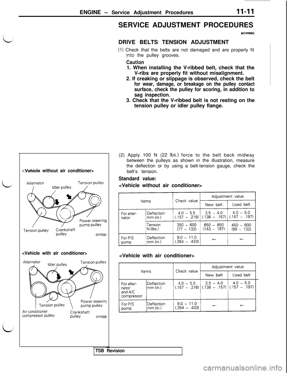
AlternatorTension pulley
IIdler pulley/
Tension pulleyCrankshaftpulleyOlFOOO
Tenston pulley
Air conditionerCrankshaftcompressor pulleypulleyOlFOO8
,
MllFMBGDRIVE BELTS TENSION ADJUSTMENT
(1) Check that the belts are not damaged and are properly fit
,into the pulley grooves.
Caution1. When installing the V-ribbed belt, check that the
V-ribs are properly fit without misalignment.
2. If creaking or slippage is observed, check the belt
for wear, damage, or breakage on the pulley contact
surface, check the pulley for scoring, in addition to
sag inspection.3. Check that the V-ribbed belt is not resting on the
tension pulley or idler pulley flange.
(2) Apply 100 N (22
Ibs.) force to the belt back midway
between the pulleys as shown in the illustration, measure
the deflection or by using a belt-tension gauge, check the
belt’s tension.
Standard value:
Tension350-600650-850450-600N (Ibs.)(77-132)(143-187)(99-132)
For P/S
pump
ItemsAdjustment valueCheck valueNew beltUsed belt
TSB Revision
Page 62 of 1146
II-12ENGINE - Service Adjustment Procedures-
r
AdJl
bolt
Alternator wllev
haft
Fixing nutOlFOOO8
Alternator pulley
Adjusting bolt
/Crankshaftpulley
Air contionercompressorpulleyw Tension pulleyFlxtng nutOlN007.
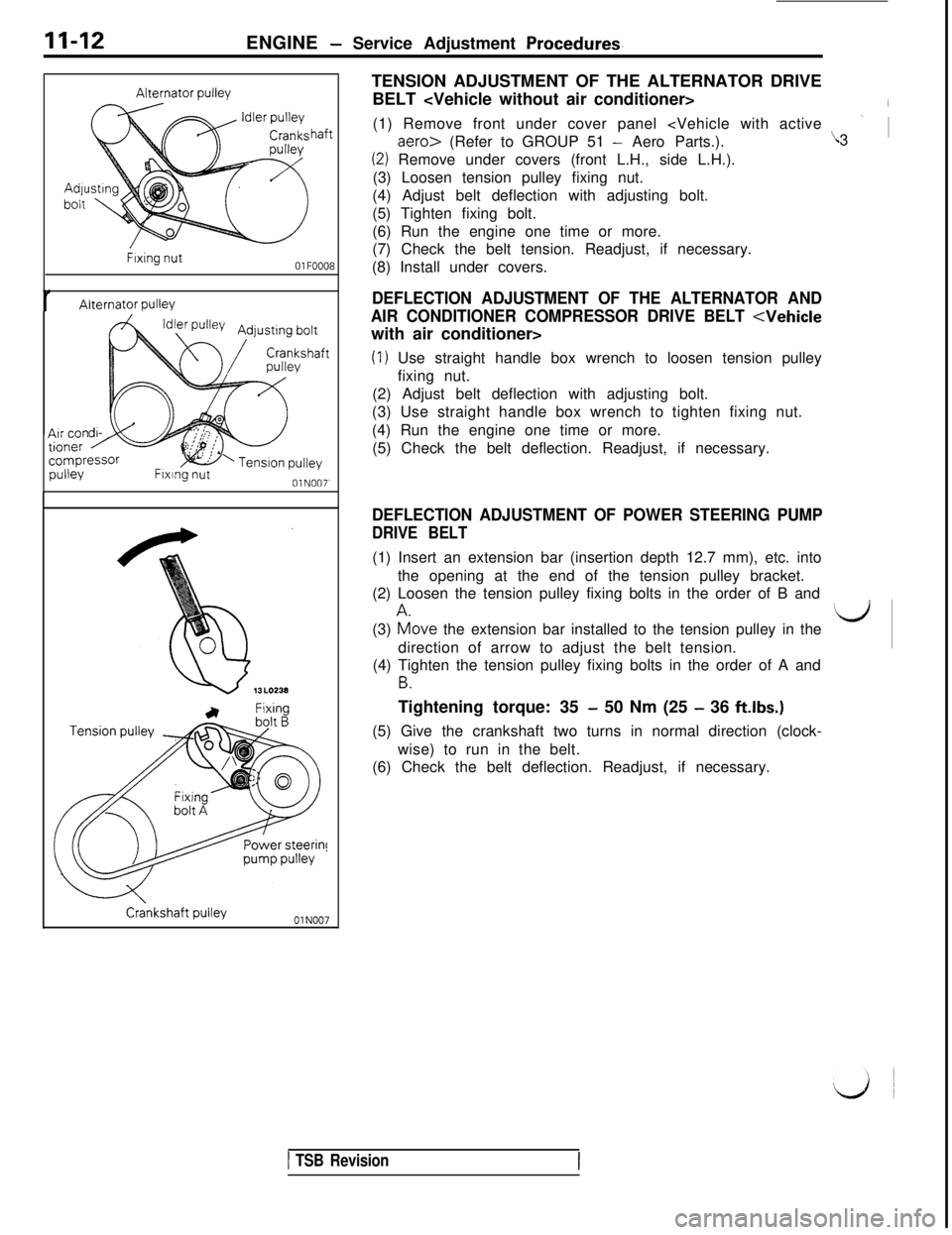
Crankshaft pulleyOlN007TENSION ADJUSTMENT OF THE ALTERNATOR DRIVE
BELT
I(1) Remove front under cover panel
aero> (Refer to GROUP 51 - Aero Parts.).\\
3 ’
(2) Remove under covers (front L.H., side L.H.).
(3) Loosen tension pulley fixing nut.
(4) Adjust belt deflection with adjusting bolt.
(5) Tighten fixing bolt.
(6) Run the engine one time or more.
(7) Check the belt tension. Readjust, if necessary.
(8) Install under covers.
DEFLECTION ADJUSTMENT OF THE ALTERNATOR AND
AIR CONDITIONER COMPRESSOR DRIVE BELT
(1) Use straight handle box wrench to loosen tension pulley
fixing nut.
(2) Adjust belt deflection with adjusting bolt.
(3) Use straight handle box wrench to tighten fixing nut.
(4) Run the engine one time or more.
(5) Check the belt deflection. Readjust, if necessary.
DEFLECTION ADJUSTMENT OF POWER STEERING PUMP
DRIVE BELT(1) Insert an extension bar (insertion depth 12.7 mm), etc. into
the opening at the end of the tension pulley bracket.
(2) Loosen the tension pulley fixing bolts in the order of B and
(3)
iove the extension bar installed to the tension pulley in the‘LJdirection of arrow to adjust the belt tension.
(4) Tighten the tension pulley fixing bolts in the order of A and
8.Tightening torque: 35
- 50 Nm (25 - 36 ftlbs,)(5) Give the crankshaft two turns in normal direction (clock-
wise) to run in the belt.
(6) Check the belt deflection. Readjust, if necessary.
1 TSB Revision
Page 63 of 1146
ENGINE - Service Adiustment ProceduresII-13
I_ ianltion tlminaI!H Connector for Igdpstment 6rown)
4tll II -7FUO9371IGNITION TIMING ADJUSTMENTMllFLAF
(1) The vehicle should be prepared as follows before the
inspection and adjustment.
lEngine coolant temperature: 80 - 95°C (176 - 205°F)
l Lights, electric cooling fan and accessories: OFF
l Transaxle: neutral
(P for A/T)l Steering wheel: neutral position
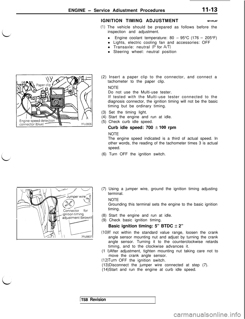
(2) Insert a paper clip to the connector, and connect a
tachometer to the paper clip.
NOTEDo not use the Multi-use tester.
If tested with the Multi-use tester connected to the
diagnosis connector, the ignition timing will not be the basic
timing but be ordinary timing.
(3) Set the timing light.
(4) Start the engine and run at idle.
(5) Check curb idle speed.
Curb idle speed: 700
f 100 rpm
NOTEThe engine speed indicated is a third of actual speed. In
other words, the reading of the tachometer times 3 is actual
speed.
(6) Turn OFF the ignition switch.
(7) Using a jumper wire, ground the ignition timing adjusting
terminal.
NOTEGrounding this terminal sets the engine to the basic ignition
timing.
\(8) Start the engine and run at idle.
(9) Check basic ignition timing.
Basic ignition timing: 5” BTDC
k 2”
(10)lf not within the standard value range, loosen the crank
angle sensor mounting nut and adjust by turning the crank
angle sensor. Turning it to the counterclockwise retards
timing, and to the clockwise advances it.
(1 l)After adjustment, tighten mounting nut taking care not to
move the crank angle sensor.
(12)Turn OFF the ignition switch.
(13)Disconnect the jumper wire connected at step (7).
(14)Start and run the engine at curb idle speed.
1 TSB Revision
Page 64 of 1146
11-14ENGINE - Service Adjustment Procedures
(15)Check to be sure that the idling ignition timing is the correct
timing.
Actual ignition timing: Approx. 15” BTDC
NOTE:d
(1) Ignition timing is variable even under normal operation.
(2) And it is automatically advanced at higher altitudes.
CURB IDLE SPEED INSPECTIONMllFMAB
(1) The vehicle should be prepared as follows before the
inspection.
lEngine coolant temperature: 80 - 95°C (176 - 205°F)
l Lights, electric cooling fan and accessories: OFF
l Transaxle: neutral
(P for A/T)l Steering wheel: neutral position
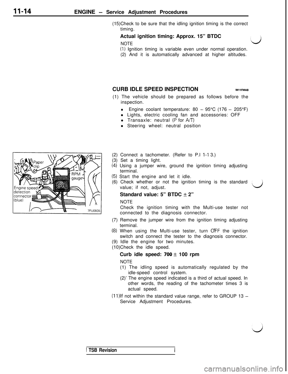
(2) Connect a tachometer. (Refer to P.l l-1 3.)
(3) Set a timing light.
(4) Using a jumper wire, ground the ignition timing adjusting
terminal.
(5) Start the engine and let it idle.
(6) Check whether or not the ignition timing is the standard
value; if not, adjust.
Standard value: 5” BTDC + 2”
NOTECheck the ignition timing with the Multi-use tester not
connected to the diagnosis connector.
(7) Remove the jumper wire from the ignition timing adjusting
terminal.
(8) When using the Multi-use tester, turn OFF the ignition
switch and connect the tester to the diagnosis connector.
(9) Idle the engine for two minutes.
(10)Check the idle speed.
Curb idle speed:
700 + 100 rpm
NOTE(1) The idling speed is automatically regulated by the
idle-speed control system.
(2)’ The engine speed indicated is a third of actual speed. In
other words, the reading of the tachometer times 3 is
actual speed.
(1l)lf not within the standard value range, refer to GROUP 13 -Service Adjustment Procedures.
d
1 TSB RevisionI
Page 65 of 1146
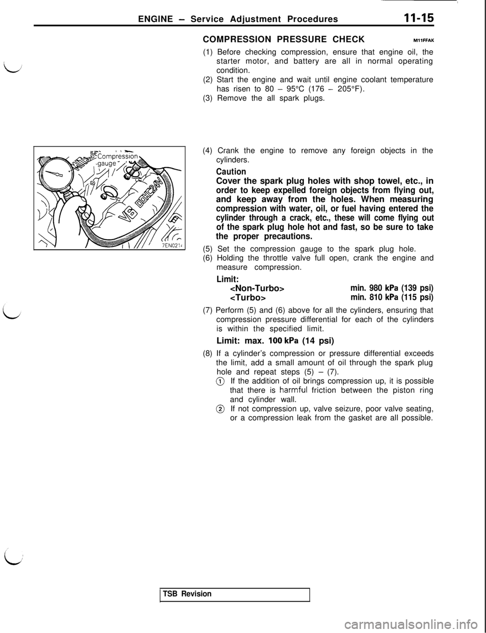
ENGINE - Service Adjustment Procedures11-15COMPRESSION PRESSURE CHECKMllFFAK
(1) Before checking compression, ensure that engine oil, the
starter motor, and battery are all in normal operating
condition.
(2) Start the engine and wait until engine coolant temperature
has risen to 80
- 95°C (176 - 205°F).
(3) Remove the all spark plugs.
(4) Crank the engine to remove any foreign objects in the
cylinders.
CautionCover the spark plug holes with shop towel, etc., in
order to keep expelled foreign objects from flying out,and keep away from the holes. When measuring
compression with water, oil, or fuel having entered the
cylinder through a crack, etc., these will come flying out
of the spark plug hole hot and fast, so be sure to take
the proper precautions.(5) Set the compression gauge to the spark plug hole.
(6) Holding the throttle valve full open, crank the engine and
measure compression.
Limit:
min. 980 kPa (139 psi)
min. 810 kPa (115 psi)(7) Perform (5) and (6) above for all the cylinders, ensuring that
compression pressure differential for each of the cylinders
is within the specified limit.
Limit: max.
100 kPa (14 psi)
(8) If a cylinder’s compression or pressure differential exceeds
the limit, add a small amount of oil through the spark plug
hole and repeat steps (5)
- (7).@If the addition of oil brings compression up, it is possible
that there is
harmf,uI friction between the piston ring
and cylinder wall.@If not compression up, valve seizure, poor valve seating,
or a compression leak from the gasket are all possible.
TSB Revision
Page 66 of 1146
11-16ENGINE - Service Adjustment Procedures
MANIFOLD VACUUM INSPECTION
MllFNAR
(1) The vehicle should be repaired as follows before the
inspection.
lEngine coolant temperature: 80 - 95°C (176 - 205°F)‘dl Lights, electric cooling fan, and accessories: OFF
l Transaxle: Neutral
(P for A/T)l Steering wheel: neutral position
(2) Connect a tachometer. (Refer to P.l l-l 3.)
(3) Disconnect the vacuum hose from the nipple for taking off
fuel pressure regulator vacuum from the air intake plenum.
(4) Conncet a three-way joint between the removed vacuum
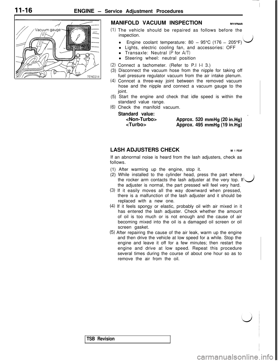
hose and the nipple and connect a vacuum gauge to the
joint.
(5) Start the engine and check that idle speed is within the
standard value range.
(6) Check the manifold vacuum.
Standard value:
*
Approx. 495 mmHg (19 in.Hg)LASH ADJUSTERS CHECK
Ml 1 FEAFIf an abnormal noise is heard from the lash adjusters, check as
follows.
(1) After warming up the engine, stop it.
(2) While installed to the cylinder head, press the part where
the rocker arm contacts the lash adjuster at the very top. If
the adjuster is normal, the part pressed will feel very hard.
d
(3) If it easily moves all the way downward when pressed,
there is a malfunction of the lash adjuster and it should be
replaced with a new one.
(4) If it feels spongy or elastic, probably oil with air mixed in it
has entered the lash adjuster. Check whether the amount
of oil is too much or is not enough and the cause of air
becoming mixed into the oil is a damaged oil screen or oil
screen gasket.
(5) After repairing the cause of the air leak, warm up the engine
and then drive the vehicle at low speed for a while. Stop the
engine and leave it off for a few minutes; then restart the
engine and drive at low speed. Repeat this procedure
several times during the course of about one hour so as to
remove the air from the oil.
TSB Revision
Page 67 of 1146
ENGINE - Engine AssemblyII-17
ENGINE ASSEMBLY
/REMOVAL AND INSTALLATION
I
Pre-removal Operationl Release of Residual Pressure from HighPressure Fuel Hose(Refer to GROUP 13 -Service AdjustmentProcedures,)l Removal of Cruise Control Pump andLink Assembly(Refer to GROUP 13 - Cruise Control.)l Removal of Hood(RefertoGROUP42A-Hood.)
l
Removal of Air Hose and Air Pipe
Post-installation Operationl Installation of Radiator(Refer to GROUP 14 - Radiator.)l Installation of Cruise Control Pump andLink Assembly(Refer to GROUP 13 -Cruise Control.)l Installation of Transaxle Assembly(Refer to GROUP 22,23 -Transaxle Assembly.)l lnstallatron of Front Exhaust Pipe(Refer to GROUP 15 - Exhaust Pipe and Main Muffler.)l Installation of Air Hose and Air Pipe
MllSA-B
4 ft.lbs.
6
40-45 Nm
29 - 33 fklbs.
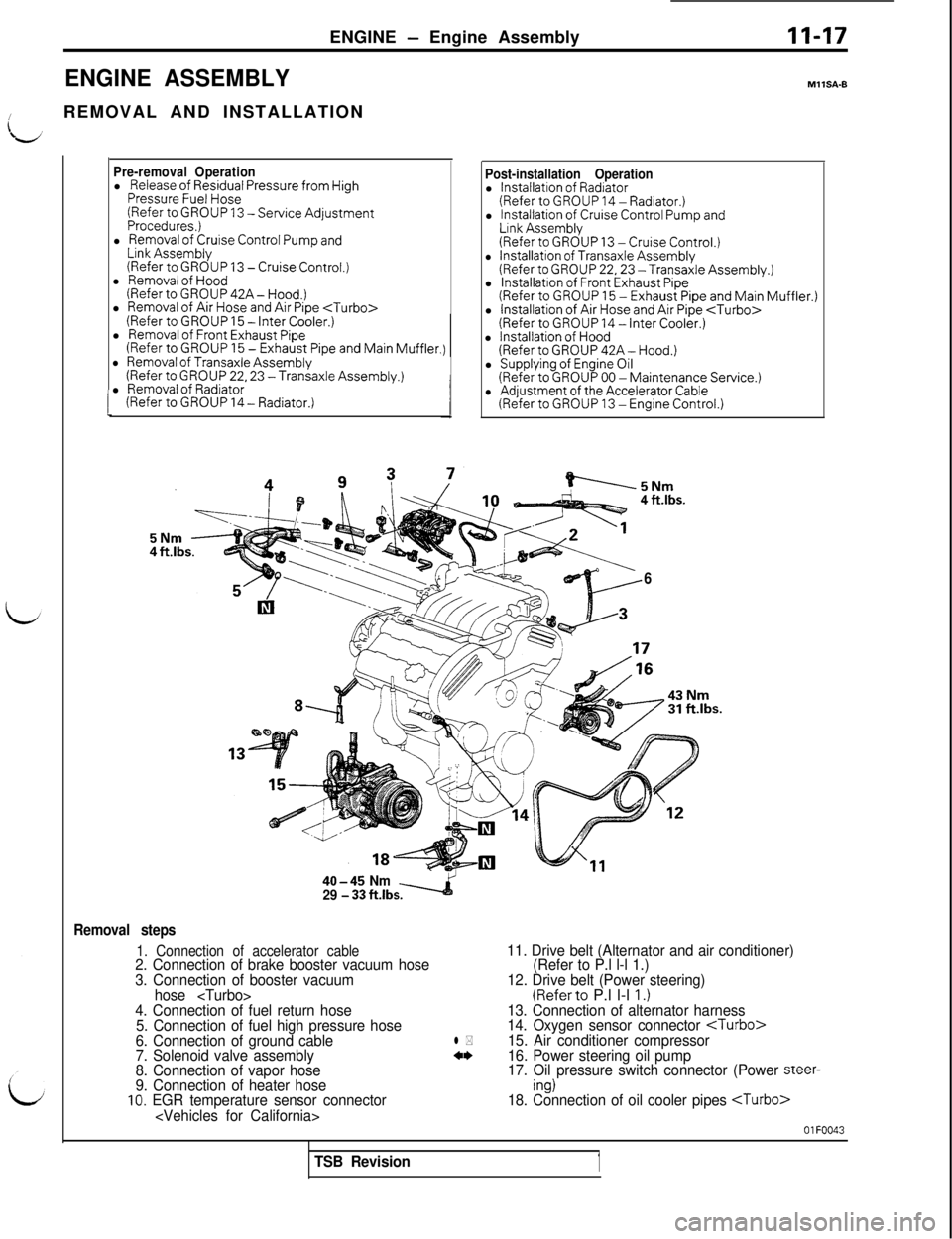
Removal steps
1. Connection of accelerator cable11. Drive belt (Alternator and air conditioner)
2. Connection of brake booster vacuum hose(Refer to P.l l-l 1.)
3. Connection of booster vacuum12. Drive belt (Power steering)
hose
(Referto P.l l-l I.)4. Connection of fuel return hose13. Connection of alternator harness
5. Connection of fuel high pressure hose14. Oxygen sensor connector
6. Connection of ground cablel *15. Air conditioner compressor
7. Solenoid valve assembly4w
16. Power steering oil pump
8. Connection of vapor hose17. Oil pressure switch connector (Power steer-9. Connection of heater hoseing)10. EGR temperature sensor connector18. Connection of oil cooler pipes
OlFOO43
TSB Revision1
Page 68 of 1146
II-18ENGINE - Engine Assembly
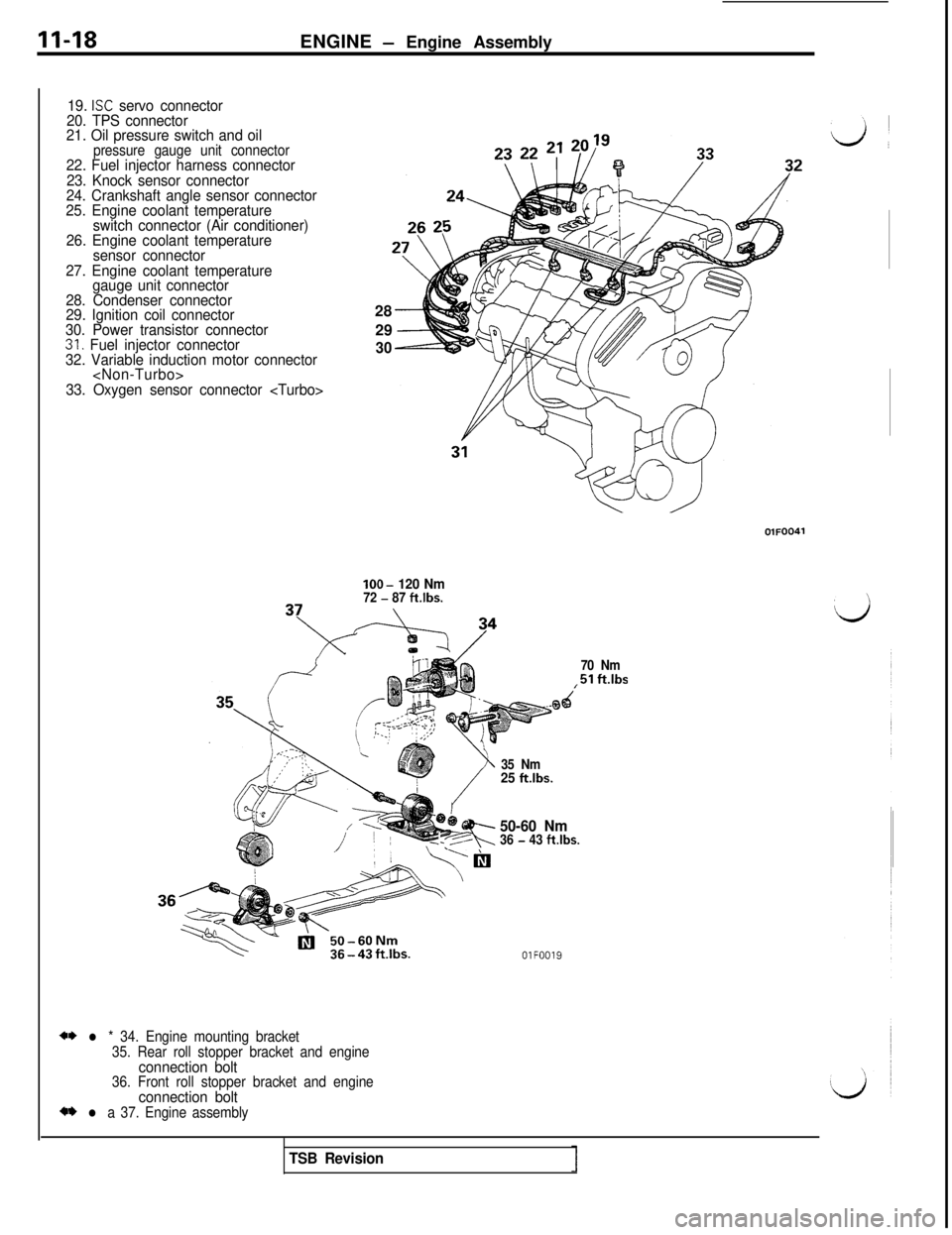
19. ISC servo connector
20. TPS connector
21. Oil pressure switch and oil
pressure gauge unit connector22. Fuel injector harness connector
23. Knock sensor connector
24. Crankshaft angle sensor connector
25. Engine coolant temperature
switch connector (Air conditioner)
26. Engine coolant temperature
sensor connector
27. Engine coolant temperature
gauge unit connector
28. Condenser connector
29. Ignition coil connector
30. Power transistor connector
31. Fuel injector connector
32. Variable induction motor connector
33. Oxygen sensor connector
2930lOO-
120 Nm72 - 87 ft.lbs.
70 Nm
,51 ftlbs
** l * 34. Engine mounting bracket
35. Rear roll stopper bracket and engine
connection bolt36. Front roll stopper bracket and engineconnection bolt** l a 37. Engine assembly35 Nm
25 ft.lbs.
?I,---R
50-60 Nm36 - 43 ftlbs.
OlFOO19
TSB Revision
Page 69 of 1146
ENGINE - Enaine AssemblvII-19
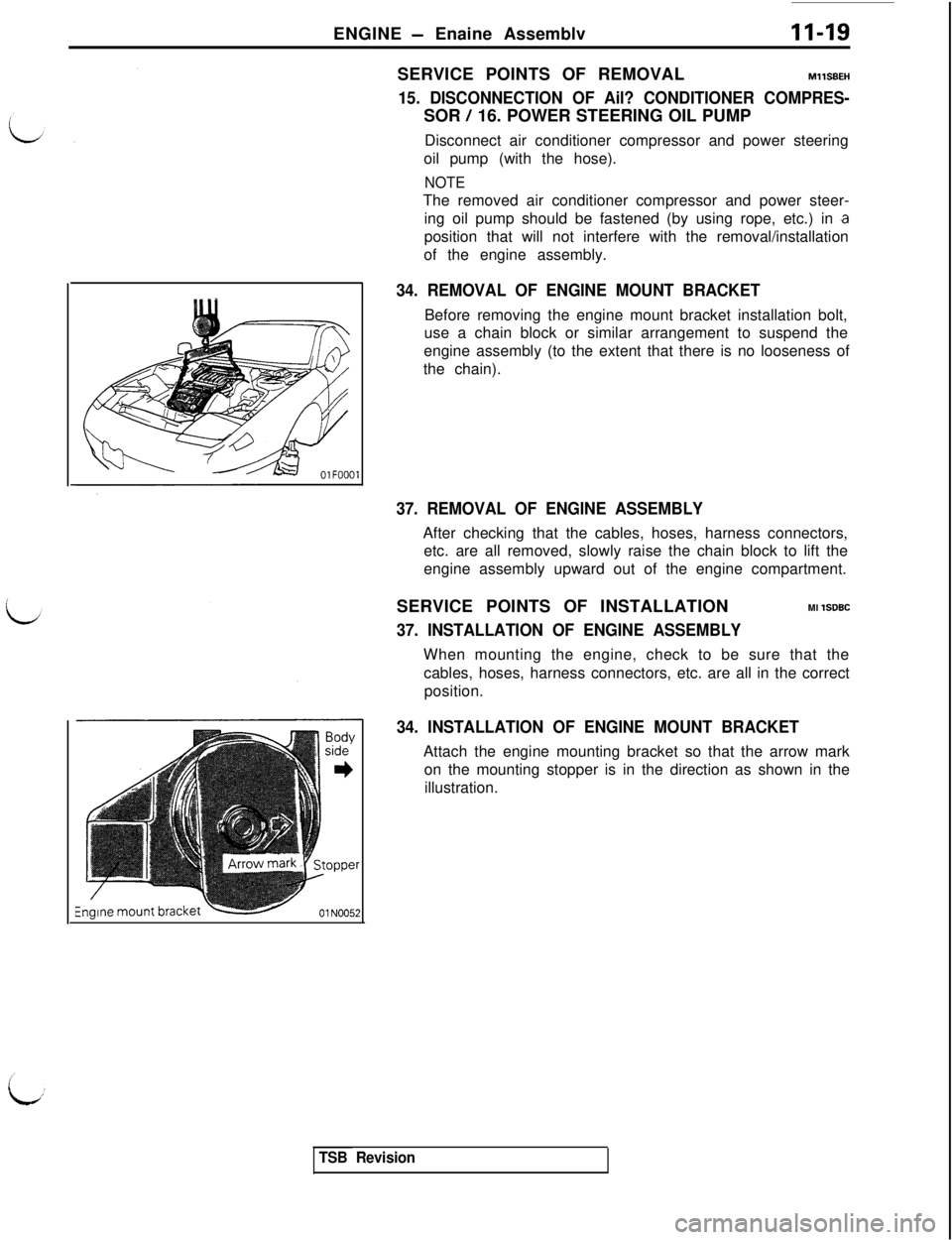
Engine mount bracketSERVICE POINTS OF REMOVALMllSBEH
15. DISCONNECTION OF Ail? CONDITIONER COMPRES-SOR
/ 16. POWER STEERING OIL PUMP
Disconnect air conditioner compressor and power steering
oil pump (with the hose).
NOTEThe removed air conditioner compressor and power steer-
ing oil pump should be fastened (by using rope, etc.) in
.aposition that will not interfere with the removal/installation
of the engine assembly.
34. REMOVAL OF ENGINE MOUNT BRACKETBefore removing the engine mount bracket installation bolt,
use a chain block or similar arrangement to suspend the
engine assembly (to the extent that there is no looseness of
the chain).
37. REMOVAL OF ENGINE ASSEMBLYAfter checking that the cables, hoses, harness connectors,
etc. are all removed, slowly raise the chain block to lift the
engine assembly upward out of the engine compartment.
SERVICE POINTS OF INSTALLATIONMl
1SDBC
37. INSTALLATION OF ENGINE ASSEMBLYWhen mounting the engine, check to be sure that the
cables, hoses, harness connectors, etc. are all in the correct
position.
34. INSTALLATION OF ENGINE MOUNT BRACKETAttach the engine mounting bracket so that the arrow mark
on the mounting stopper is in the direction as shown in the
illustration.
TSB Revision
Page 70 of 1146
II-20ENGINE - Camshaft Oil Seals
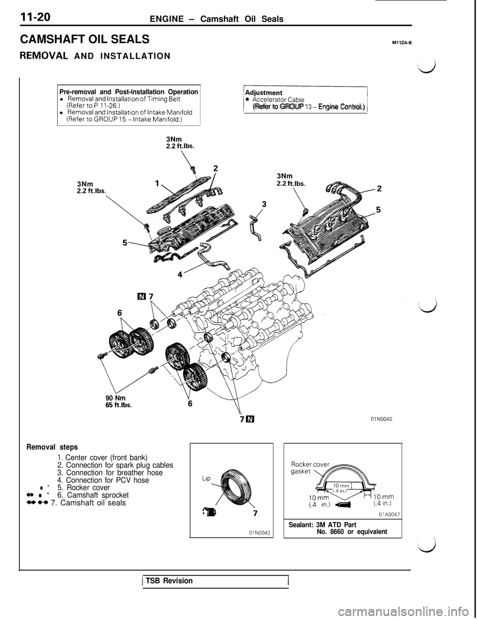
CAMSHAFT OIL SEALS
RElVjOVAL AND INSTALLATION
MllZA-B
Pre-removal and Post-installation Operationl Removal and Installation of Timing Belt(Refer to P.l l-26.)l Removal and Installation of Intake Manifold(Refer to GROUP 15 - Intake Manifold.)3Nm
2.2 ftlbs.
3Nm
2.2 f’tlbs.
$1(Refer to GROUP 13 - Engine Control.)3Nm
90 Nm65 ft.lbs.
Removal steps
1. Center cover (front bank)
2. Connection for spark plug cables
3. Connection for breather hose
4. Connection for PCV hose
l *5. Rocker cover** l *6. Camshaft sprocketa* I)* 7. Camshaft oil seals
io01 NO040
01 NO042
1.4 in.) 4(.4 in.)
OlA0047
Sealant: 3M ATD PartNo. 8660 or equivalent
1 TSB Revision