MITSUBISHI ECLIPSE 1990 Service Manual
Manufacturer: MITSUBISHI, Model Year: 1990, Model line: ECLIPSE, Model: MITSUBISHI ECLIPSE 1990Pages: 391, PDF Size: 15.27 MB
Page 151 of 391
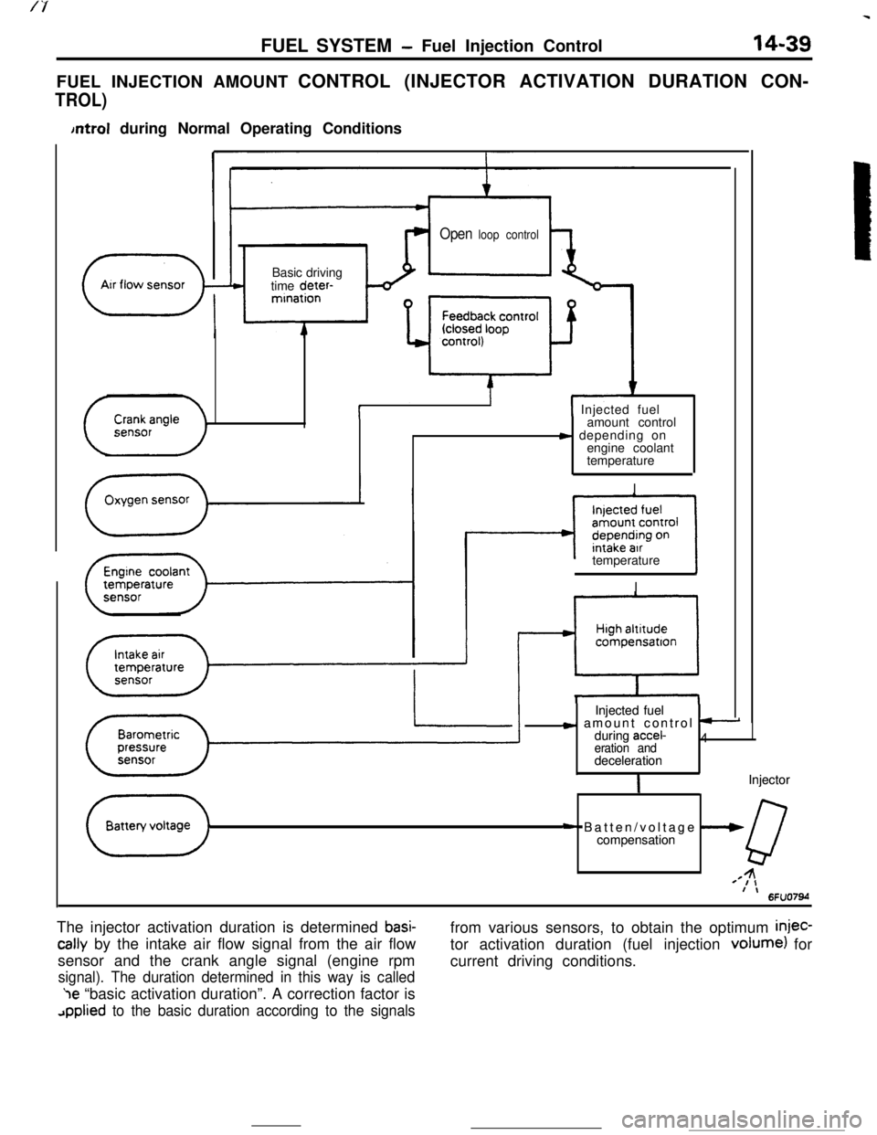
FUEL SYSTEM- Fuel Injection Control14-39FUEL INJECTION AMOUNT CONTROL (INJECTOR ACTIVATION DURATION CON-
TROL)
bntrol during Normal Operating Conditions
Open loop control
( ArrflowsensorBasic driving
time deter-
-”mination
i( Injected fuel
amount control
s depending on
engine coolant
temperature
I
II
””compensatron
Injected fuel Injected fuel
c amount control t-c amount control t-during accel-during accel-4 4eration and eration anddeceleration decelerationIIInjector Injector
+ Batten/voltage --W+ Batten/voltage --Wcompensation compensation
QQ44=I,=I,f \f \6FU07M6FU07Mtemperature
II
The injector activation duration is determined
basi-
tally by the intake air flow signal from the air flow
sensor and the crank angle signal (engine rpm
signal). The duration determined in this way is called‘le “basic activation duration”. A correction factor is
applied to the basic duration according to the signalsfrom various sensors, to obtain the optimum
injec-tor activation duration (fuel injection volume) for
current driving conditions.
Page 152 of 391
14-40FUEL SYSTEM - Fuel Injection Control
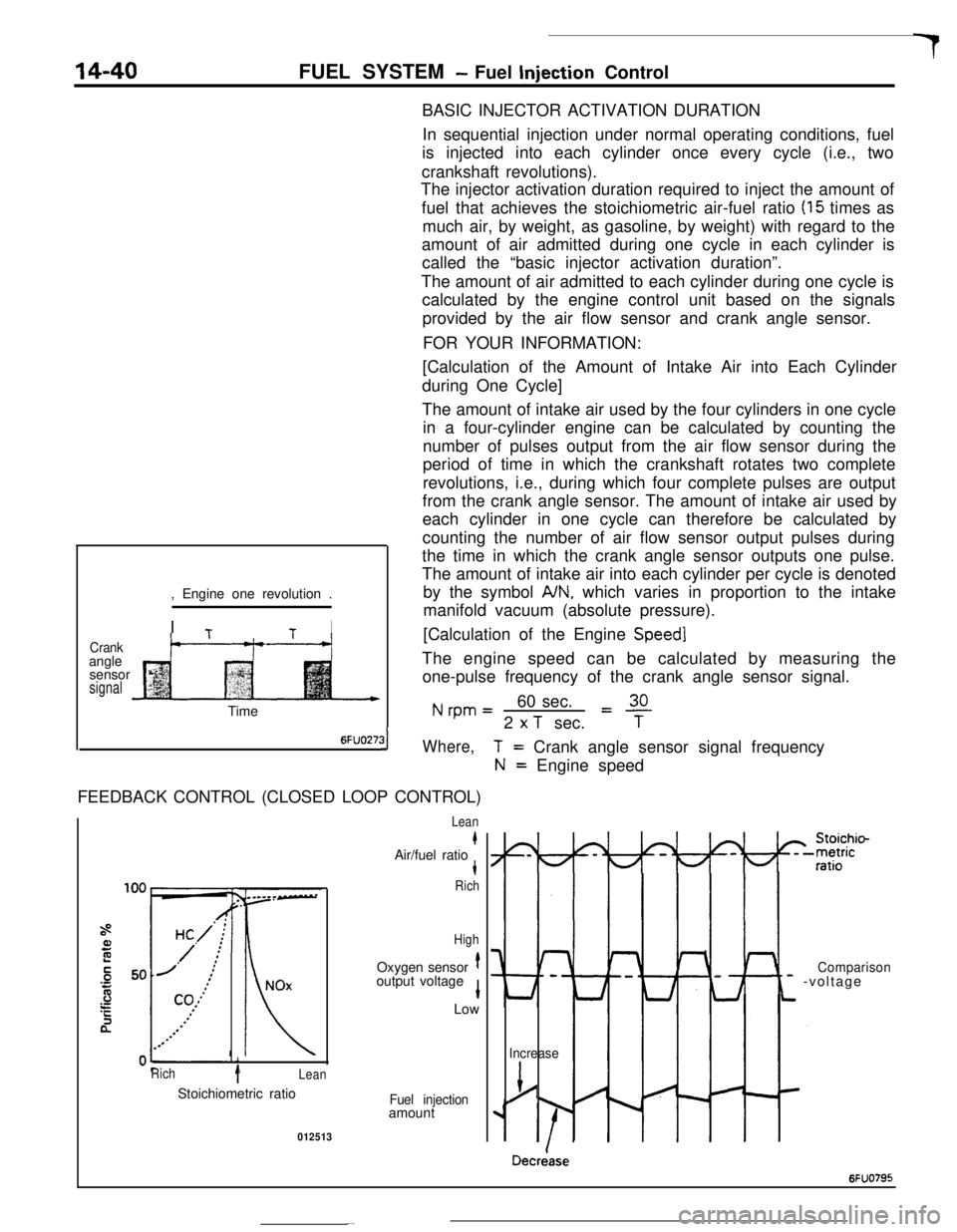
BASIC INJECTOR ACTIVATION DURATION
In sequential injection under normal operating conditions, fuel
is injected into each cylinder once every cycle (i.e., two
crankshaft revolutions).
The injector activation duration required to inject the amount of
fuel that achieves the stoichiometric air-fuel ratio
(15 times as
much air, by weight, as gasoline, by weight) with regard to the
amount of air admitted during one cycle in each cylinder is
called the “basic injector activation duration”.
The amount of air admitted to each cylinder during one cycle is
calculated by the engine control unit based on the signals
provided by the air flow sensor and crank angle sensor.
FOR YOUR INFORMATION:
Crankangle
sensor
signal, Engine one revolution .
I
TtI
t--“---t-+[Calculation of the Amount of Intake Air into Each Cylinder
during One Cycle]
The amount of intake air used by the four cylinders in one cycle
in a four-cylinder engine can be calculated by counting the
number of pulses output from the air flow sensor during the
period of time in which the crankshaft rotates two complete
revolutions, i.e., during which four complete pulses are output
from the crank angle sensor. The amount of intake air used by
each cylinder in one cycle can therefore be calculated by
counting the number of air flow sensor output pulses during
the time in which the crank angle sensor outputs one pulse.
The amount of intake air into each cylinder per cycle is denoted
by the symbol
A/N, which varies in proportion to the intake
manifold vacuum (absolute pressure).
[Calculation of the Engine
Speed]The engine speed can be calculated by measuring the
one-pulse frequency of the crank angle sensor signal.
Nrpm=60 sec.L!!L2
x T sec.TTime
6FUO27:31Where,FEEDBACK CONTROL (CLOSED LOOP CONTROL)
i
Rich1Lean
T= Crank angle sensor signal frequency
N= Engine speed
Lean
kAir/fuel ratiot
Rich
HighOxygen sensor
toutput voltage
1Low
Stoichiometric ratio
Fuel injectionamount
012513
I-
Lt
Comparison- -voltage
Increase
j/
Decriase
6FUO795
Page 153 of 391
FUEL SYSTEM -Fuel Injection Control
14-41
During normal operation (including idling), the en-
gine control unit controls the injector activation time
tcThieve the stoichiometric air/fuel ratio, which
e.;res maximum efficiency of the catalytic conver-
ter, on the basis of the oxygen sensor signal.
When the air/fuel mixture is richer than the
stoichiometric ratio, there is less oxygen in the
exhaust gas and thus the oxygen sensor output
voltage is higher; hence a “mixture rich” signal is
input to the engine control unit. Then, the engine
control unit decreases the amount of fuel injected. If
the air/fuel ratio decreases to the point that and the
mixture becomes leaner than the stoichiometric
ratio, the oxygen concentration in the exhaust gas
increases and the oxygen sensor output voltage
becomes lower. Then, a “mixture lean” signal isinput to the engine control unit.
Upon input of this signal, the engine control unit
increases the feedback correction factor, thus caus-
ing more fuel to be injected.
By means of the above-mentioned controls (collec-
tively called “feedback control”), the air-fuel mixture
is maintained at the stoichiometric ratio.
Under the following specific conditions, this feed-
back control is not performed, in order to improve
driveability.
(11
(2)
::I
(5)While cranking the engine
During engine warm-up when engine coolant
temperature is less than
45°C (113°F)During acceleration/deceleration
During high load operation
When oxygen sensor is not functioning
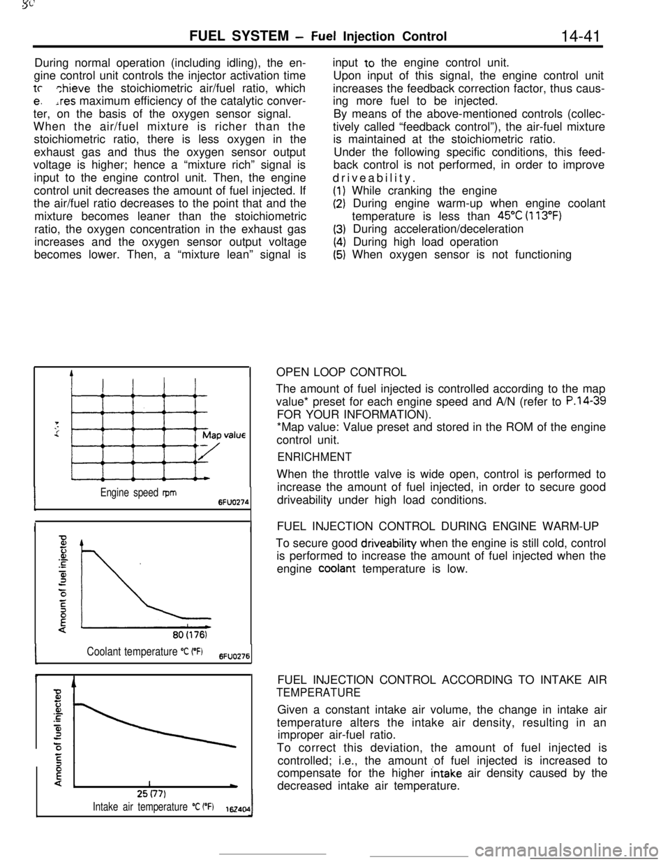
IOPEN LOOP CONTROL
Engine speed rpm6FUO274
II
80(176)
Coolant temperature “C (“Fj6FlJO276
I425(77)
Intake air temperature “C (“F)1~40,0IThe amount of fuel injected is controlled according to the map
value* preset for each engine speed and A/N (refer to
P.l4-39FOR YOUR INFORMATION).
*Map value: Value preset and stored in the ROM of the engine
control unit.
ENRICHMENTWhen the throttle valve is wide open, control is performed to
increase the amount of fuel injected, in order to secure good
driveability under high load conditions.
FUEL INJECTION CONTROL DURING ENGINE WARM-UP
To secure good driveability when the engine is still cold, control
is performed to increase the amount of fuel injected when the
engine
cooiant temperature is low.
FUEL INJECTION CONTROL ACCORDING TO INTAKE AIR
TEMPERATUREGiven a constant intake air volume, the change in intake air
temperature alters the intake air density, resulting in an
improper air-fuel ratio.
To correct this deviation, the amount of fuel injected is
controlled; i.e., the amount of fuel injected is increased to
compensate for the higher
intake air density caused by the
decreased intake air temperature.
Page 154 of 391
14-42
FUEL SYSTEM- Fuel Injection Control
4
Fz.or.c
4:0/
E
{!*760 (301Barometric pressure
mmHg (in.Hg) 6Fuo9z
c
Timet
6FUO279Drivecurrent
0: bri
F2JJ’ ipe; II
I+-JValve opening timi16240:
E‘C
F
.-
is
3
3:\Battery voltage
V162406
80 (176)Coolant temperature
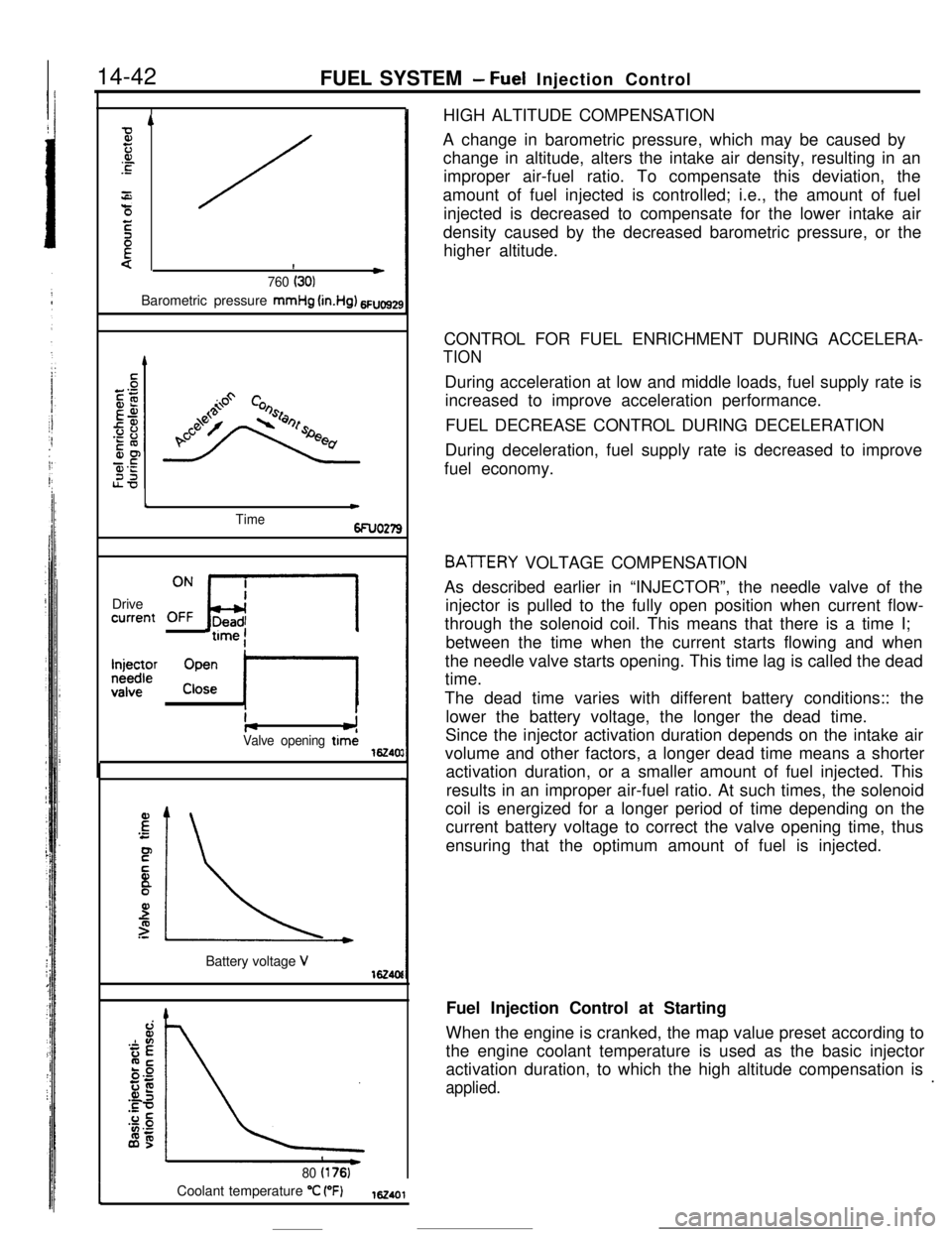
“C (“F)162401HIGH ALTITUDE COMPENSATION
A change in barometric pressure, which may be caused by
change in altitude, alters the intake air density, resulting in an
improper air-fuel ratio. To compensate this deviation, the
amount of fuel injected is controlled; i.e., the amount of fuel
injected is decreased to compensate for the lower intake air
density caused by the decreased barometric pressure, or the
higher altitude.
CONTROL FOR FUEL ENRICHMENT DURING ACCELERA-
TIONDuring acceleration at low and middle loads, fuel supply rate is
increased to improve acceleration performance.
FUEL DECREASE CONTROL DURING DECELERATION
During deceleration, fuel supply rate is decreased to improve
fuel economy.
BATTERY VOLTAGE COMPENSATION
As described earlier in “INJECTOR”, the needle valve of the
injector is pulled to the fully open position when current flow-
through the solenoid coil. This means that there is a time I;
between the time when the current starts flowing and when
the needle valve starts opening. This time lag is called the dead
time.
The dead time varies with different battery conditions:: the
lower the battery voltage, the longer the dead time.
Since the injector activation duration depends on the intake air
volume and other factors, a longer dead time means a shorter
activation duration, or a smaller amount of fuel injected. This
results in an improper air-fuel ratio. At such times, the solenoid
coil is energized for a longer period of time depending on the
current battery voltage to correct the valve opening time, thus
ensuring that the optimum amount of fuel is injected.
Fuel Injection Control at Starting
When the engine is cranked, the map value preset according to
the engine coolant temperature is used as the basic injector
activation duration, to which the high altitude compensation is
applied..
Page 155 of 391
FUEL SYSTEM - Fuel Injection Control14-43
Time
6FUO26
Engine has started.
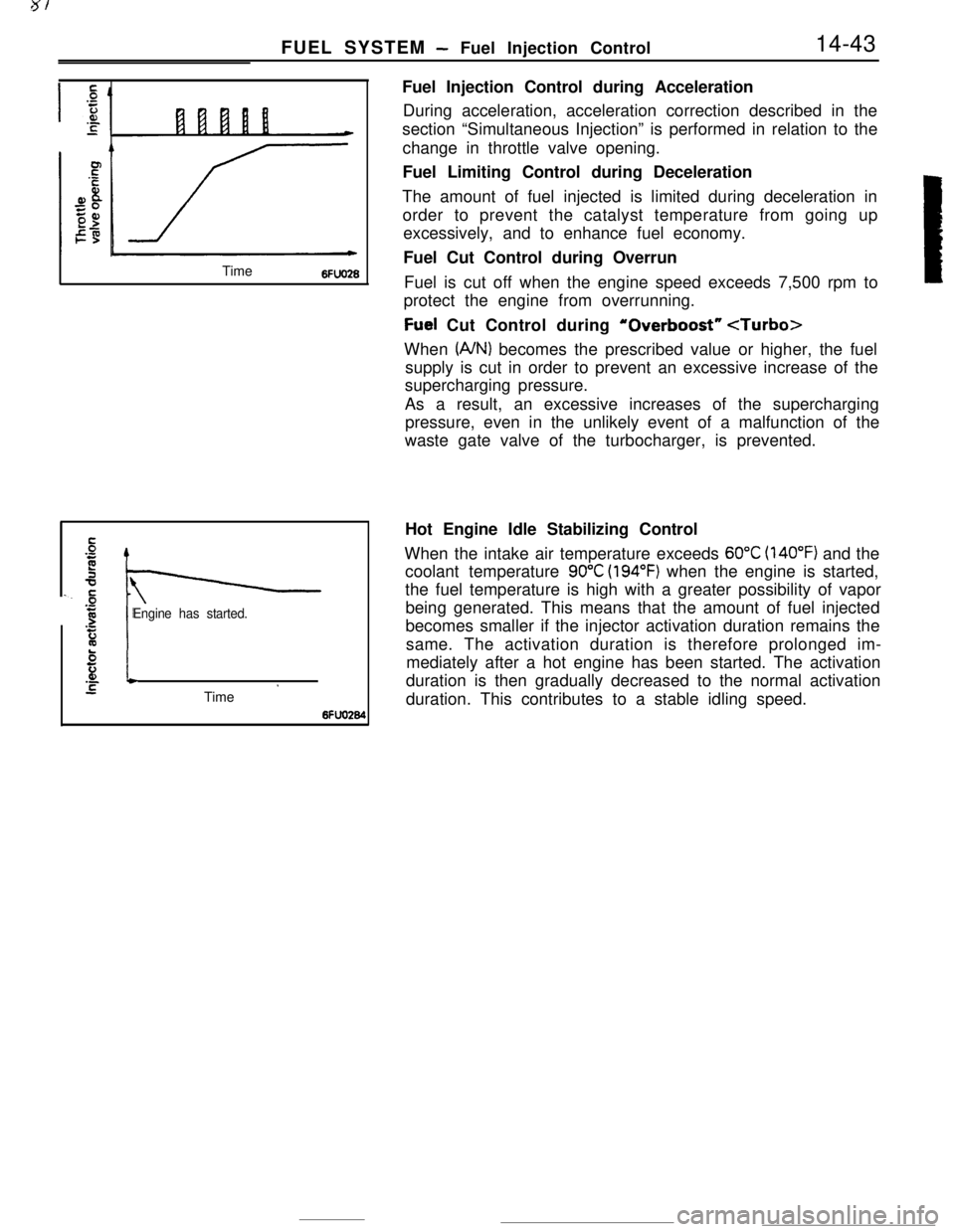
El.-*STime ’6fFuel Injection Control during Acceleration
During acceleration, acceleration correction described in the
section “Simultaneous Injection” is performed in relation to the
change in throttle valve opening.
Fuel Limiting Control during Deceleration
The amount of fuel injected is limited during deceleration in
order to prevent the catalyst temperature from going up
excessively, and to enhance fuel economy.
Fuel Cut Control during Overrun
Fuel is cut off when the engine speed exceeds 7,500 rpm to
protect the engine from overrunning.
Fuel Cut Control during ‘Overboost”
(A/N) becomes the prescribed value or higher, the fuel
supply is cut in order to prevent an excessive increase of the
supercharging pressure.
As a result, an excessive increases of the supercharging
pressure, even in the unlikely event of a malfunction of the
waste gate valve of the turbocharger, is prevented.
Hot Engine Idle Stabilizing Control
When the intake air temperature exceeds
60°C (140°F) and the
coolant temperature
90°C (194°F) when the engine is started,
the fuel temperature is high with a greater possibility of vapor
being generated. This means that the amount of fuel injected
becomes smaller if the injector activation duration remains the
same. The activation duration is therefore prolonged im-
mediately after a hot engine has been started. The activation
duration is then gradually decreased to the normal activation
duration. This contributes to a stable idling speed.
Page 156 of 391
- __..--
14-44FUEL SYSTEM- Idle Speed Control
IDLE SPEED CONTROL
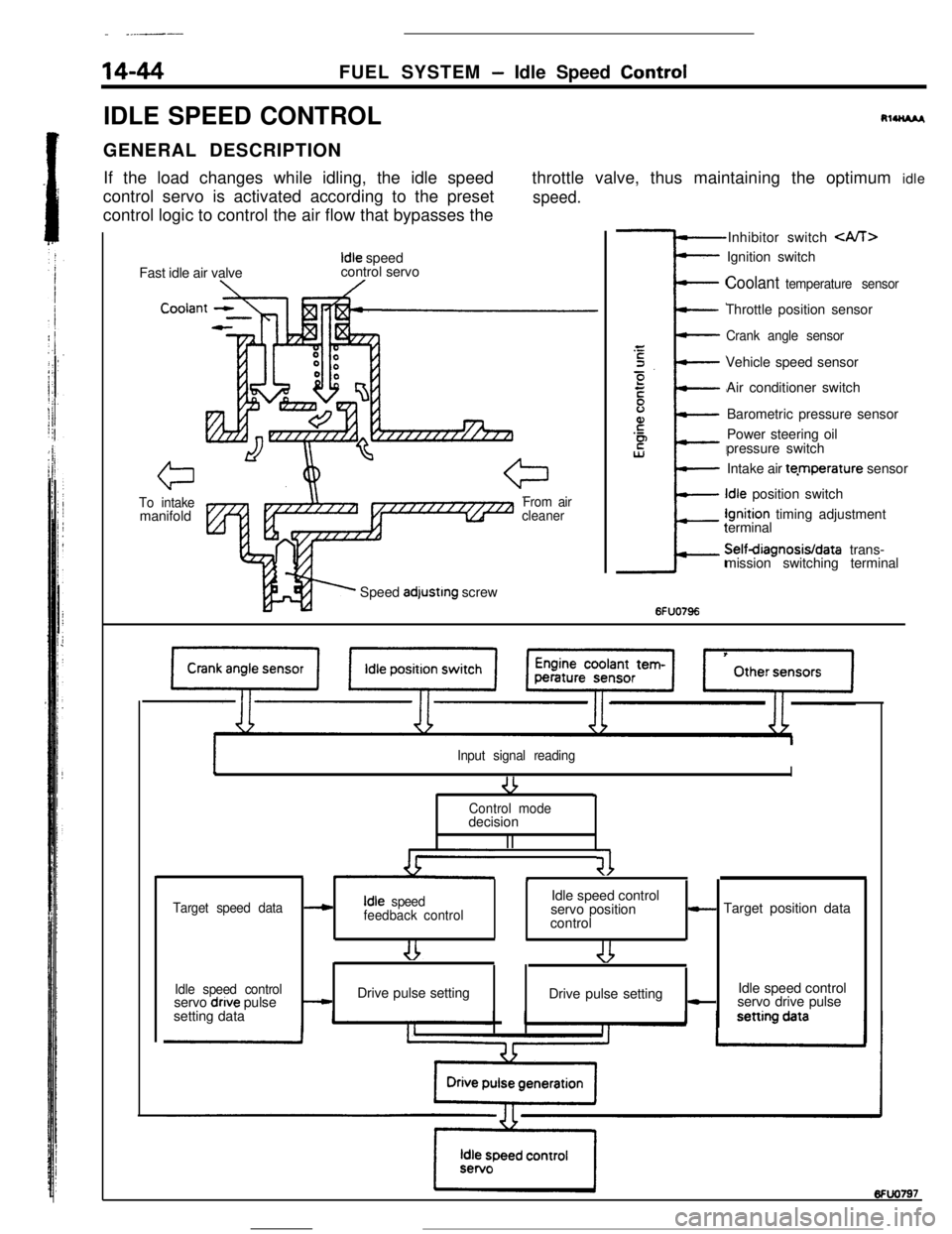
RlUU*I,GENERAL DESCRIPTION
If the load changes while idling, the idle speed
control servo is activated according to the preset
control logic to control the air flow that bypasses thethrottle valve, thus maintaining the optimum idle
speed.Fast idle air valve
Idle speed
control servo
Cooiar
To intakemanifoldFrom air
cleanerSpeed
adjustrng screwInhibitor switch
Coolant temperature sensorThrottle position sensor
Crank angle sensorVehicle speed sensor
Air conditioner switch
Barometric pressure sensor
Power steering oil
pressure switch
Intake air te.mperature sensorIdle position switchIgnition timing adjustment
terminalSelfdiagnosisIdata trans-
mission switching terminal
6FUO796
Input signal reading
-3I9Control modedecision
II
41*
Target speed dataIdle speed control---cIdle speed
feedback controlservo position- Target position data
control
Idle speed controlIdle speed control
servo dnve pulse-Drive pulse setting
Drive pulse setting-servo drive pulse
setting data
Page 157 of 391
3-d__- .
FUEL SYSTEM
-Idle Speed Control14-45IDLE SPEED CONTROL SERVO
L
PtntleThrottle bodv
Idle speed control
servo
Extend
7 -IMagnet rotordoil
/Stepper motor
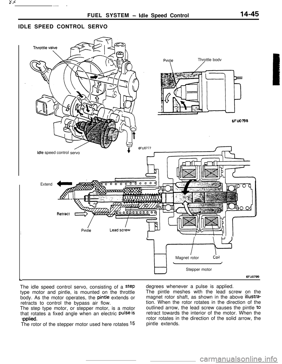
6FUO799The idle speed control servo, consisting of a
steptype motor and pintle, is mounted on the throttle
body. As the motor operates, the pintie extends or
retracts to control the bypass air flow.
The step type motor, or stepper motor, is a motor
that rotates a fixed angle when an electric
Pulse is
rpplied.The rotor of the stepper motor used here rotates
15degrees whenever a pulse is applied.
The pintle meshes with the lead screw on the
magnet rotor shaft, as shown in the above
illustra-tion. When the rotor rotates in the direction of the
outlined arrow, the lead screw causes the pintle t0
retract towards the interior of the motor. When the
rotor rotates in the direction of the solid arrow, the
pintle extends.
Page 158 of 391
.
14-46FUEL SYSTEM- Idle Speed Control
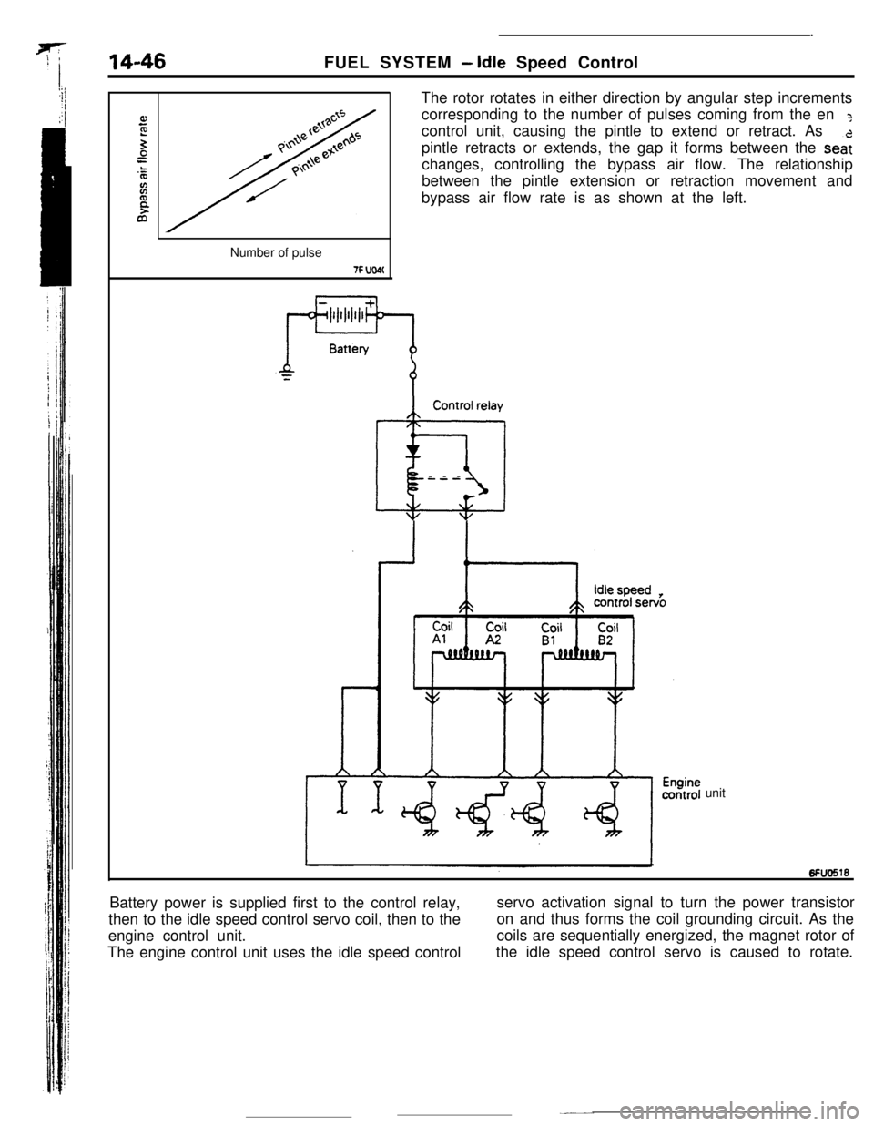
The rotor rotates in either direction by angular step increments
corresponding to the number of pulses coming from the en
?control unit, causing the pintle to extend or retract. As
pintle retracts or extends, the gap it forms between the
sea:changes, controlling the bypass air flow. The relationship
between the pintle extension or retraction movement and
bypass air flow rate is as shown at the left.
Number of pulse
7F UW(Control relay
@iI---
unit
Battery power is supplied first to the control relay,
then to the idle speed control servo coil, then to theservo activation signal to turn the power transistor
engine control unit.on and thus forms the coil grounding circuit. As the
The engine control unit uses the idle speed controlcoils are sequentially energized, the magnet rotor of
the idle speed control servo is caused to rotate.
Page 159 of 391
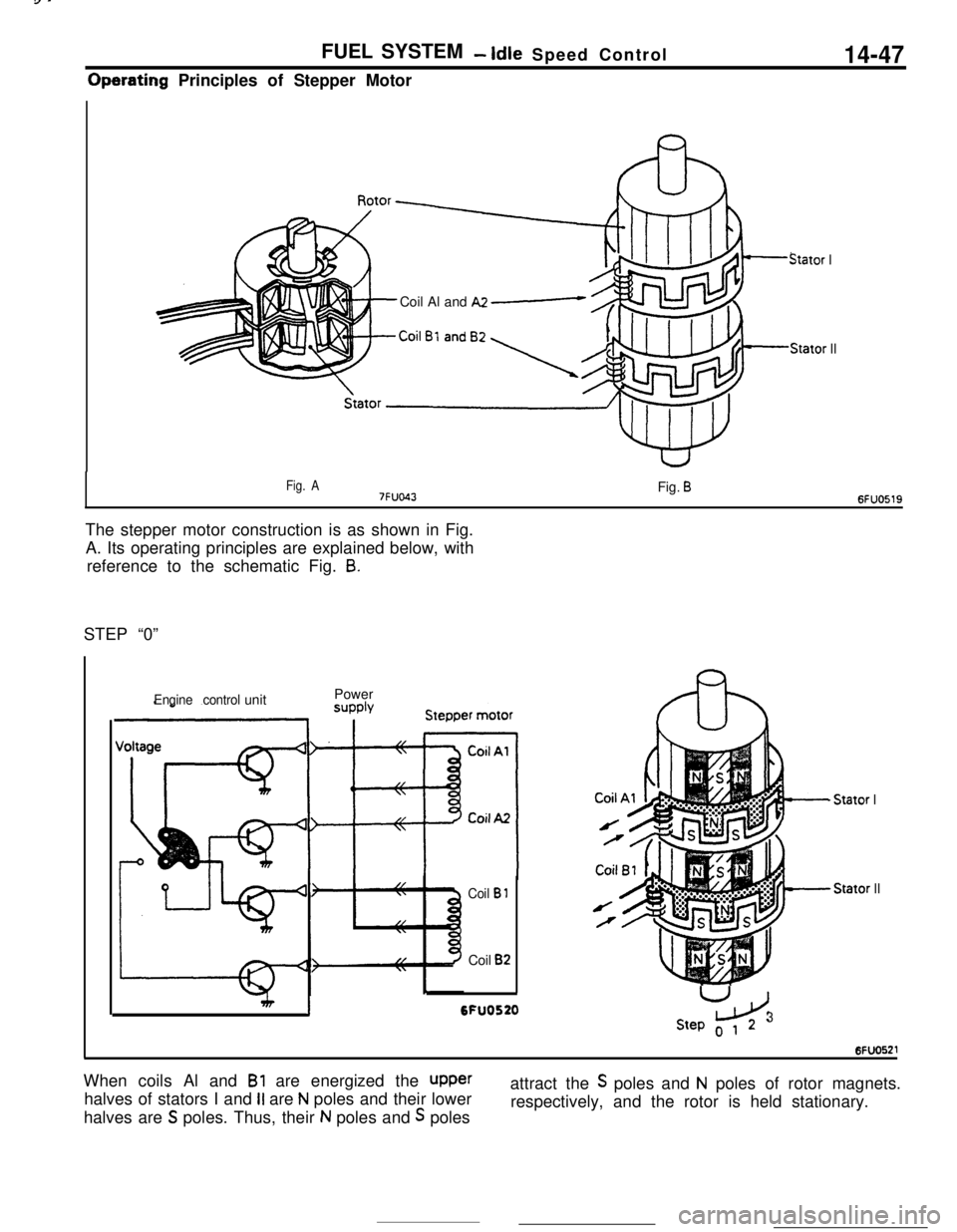
FUEL SYSTEM- Idle Speed Control14-47Operating Principles of Stepper Motor
Stator ICoil Al and
A2 e
Stator II
Fig. A7FUO43Fig. B6FUO519The stepper motor construction is as shown in Fig.
A. Its operating principles are explained below, with
reference to the schematic Fig.
8.STEP “0”
Engine controlunitPower
Coil B 1Coil
B2
I6FU0520
- Stator IStator
II
U
LdStep o 1 23When coils Al and
Bl are energized the upperhalves of stators I and
II are N poles and their lower
halves are
S poles. Thus, their N poles and S polesattract the
S poles and N poles of rotor magnets.
respectively, and the rotor is held stationary.
Page 160 of 391
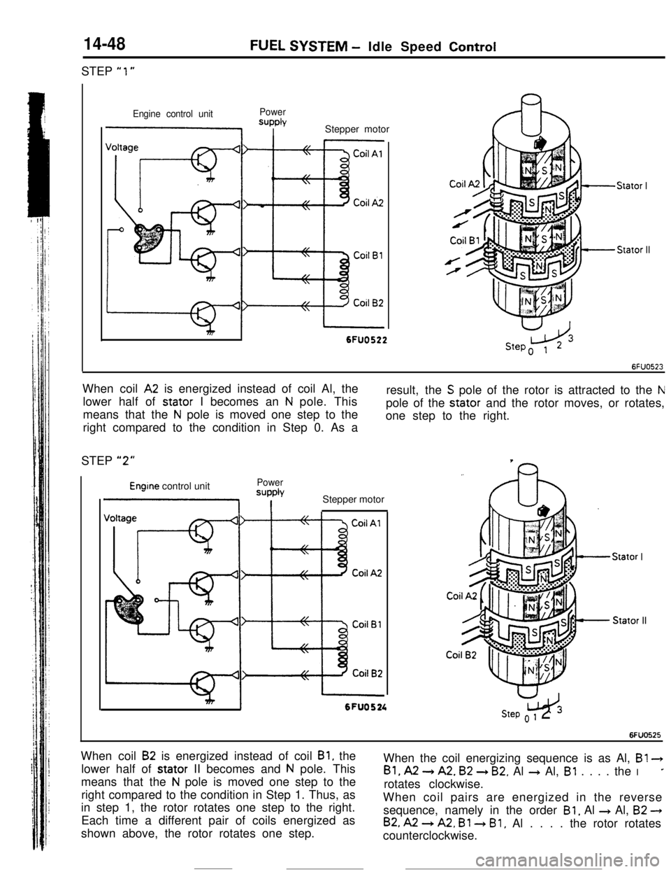
14-48STEP
“1”
FUEL SYSTEM - Idle Speed Control
Engine control unitPowerSUPPlYI IStepper motor
Stator I
Stator II
I6FUO522When coil
A2 is energized instead of coil Al, the
lower half of stator I becomes an
N pole. This
means that the
N pole is moved one step to the
right compared to the condition in Step 0. As aresult, the
S pole of the rotor is attracted to the Npole of the stator and the rotor moves, or rotates,
one step to the right.
STEP
“2”
Engine control unitPower
=JPPb
1 IStepper motor
Stator IStator II
mI6FU0524w3Step o 1 2
6FUO525When coil
B2 is energized instead of coil Bl, the
lower half of stator II becomes and
N pole. This
means that the
N pole is moved one step to the
right compared to the condition in Step 1. Thus, as
in step 1, the rotor rotates one step to the right.
Each time a different pair of coils energized as
shown above, the rotor rotates one step.When the coil energizing sequence is as Al, B!
3
Bl, A2 -) A2. B2 + B2. Al + Al, Bl . . . . the I*rotates clockwise.
When coil pairs are energized in the reverse
sequence, namely in the order
Bl, Al + Al, B2 -)
B2, A2 --) A2, Bl 3 Bl, Al . . . . the rotor rotates
counterclockwise.