MITSUBISHI ECLIPSE 1990 Service Manual
Manufacturer: MITSUBISHI, Model Year: 1990, Model line: ECLIPSE, Model: MITSUBISHI ECLIPSE 1990Pages: 391, PDF Size: 15.27 MB
Page 121 of 391
FUEL SYSTEM -Fuel Supply and Fuel Pressure Control14-9
03Poo4:Diaphragm
from intake
4Fuel from delivery pipe
4m
B(42.7)QQ
2
sl -196 2
(26.4) g
t
$!a d
9
0)Positive5 z‘. pressure
(E.2)
w
FUEL FILTERA high-pressure type filter is installed at the delivery end of the
fuel pump.
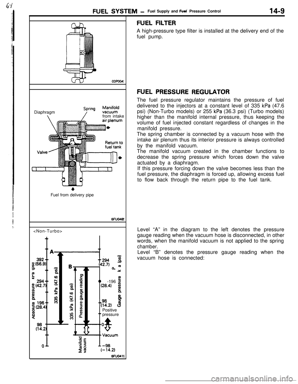
FUEL PRESSURE REGULATORThe fuel pressure regulator maintains the pressure of fuel
delivered to the injectors at a constant level of 335
kPa (47.6
psi) (Non-Turbo models) or 255
kPa (36.3 psi) (Turbo models)
higher than the manifold internal pressure, thus keeping the
volume of fuel injected constant regardless of changes in the
manifold pressure.
The spring chamber is connected by a vacuum hose with the
intake air plenum thus its interior pressure is always controlled
by the manifold vacuum.
The manifold vacuum created in the chamber functions to
decrease the spring pressure which forces down the valve
actuated by a diaphragm.
If this pressure forcing down the valve becomes less than the
fuel pressure, the diaphragm is forced up, allowing excess fuel
to flow back through the return pipe to the fuel tank.
Level “A” in the diagram to the left denotes the pressure
gauge reading when the vacuum hose is disconnected, in other
words, when the manifold vacuum is not applied to the spring
chamber.Level “B” denotes the pressure gauge reading when the
vacuum hose is connected:
Page 122 of 391
14-10
INJECTORFUEL SYSTEM
-Fuel Supply and Fuel Pressure Control
Intake port
lelivelYPipte
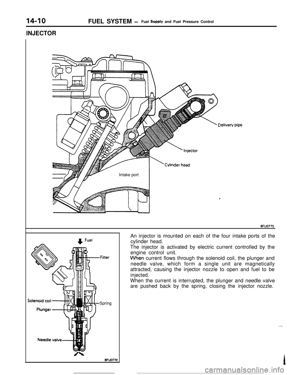
,FilterSpringAn injector is mounted on each of the four intake ports of the
cylinder head.
The injector is activated by electric current controlled by the
engine control unit.Wh-en current flows through the solenoid coil, the plunger and
needle valve, which form a single unit are magnetically
attracted, causing the injector nozzle to open and fuel to be
injected.When the current is interrupted, the plunger and needle valve
are pushed back by the spring, closing the injector nozzle.
Page 123 of 391
FUEL SYSTEM -Fuel Supply and Fuel Pressure Control
FUEL-PRESSURE CONTROL VALVE
14-11To fuel
-
Fuel-pressureregulatorFuel-pressurecontrol valve
Intake-airEnginecontrol
unit
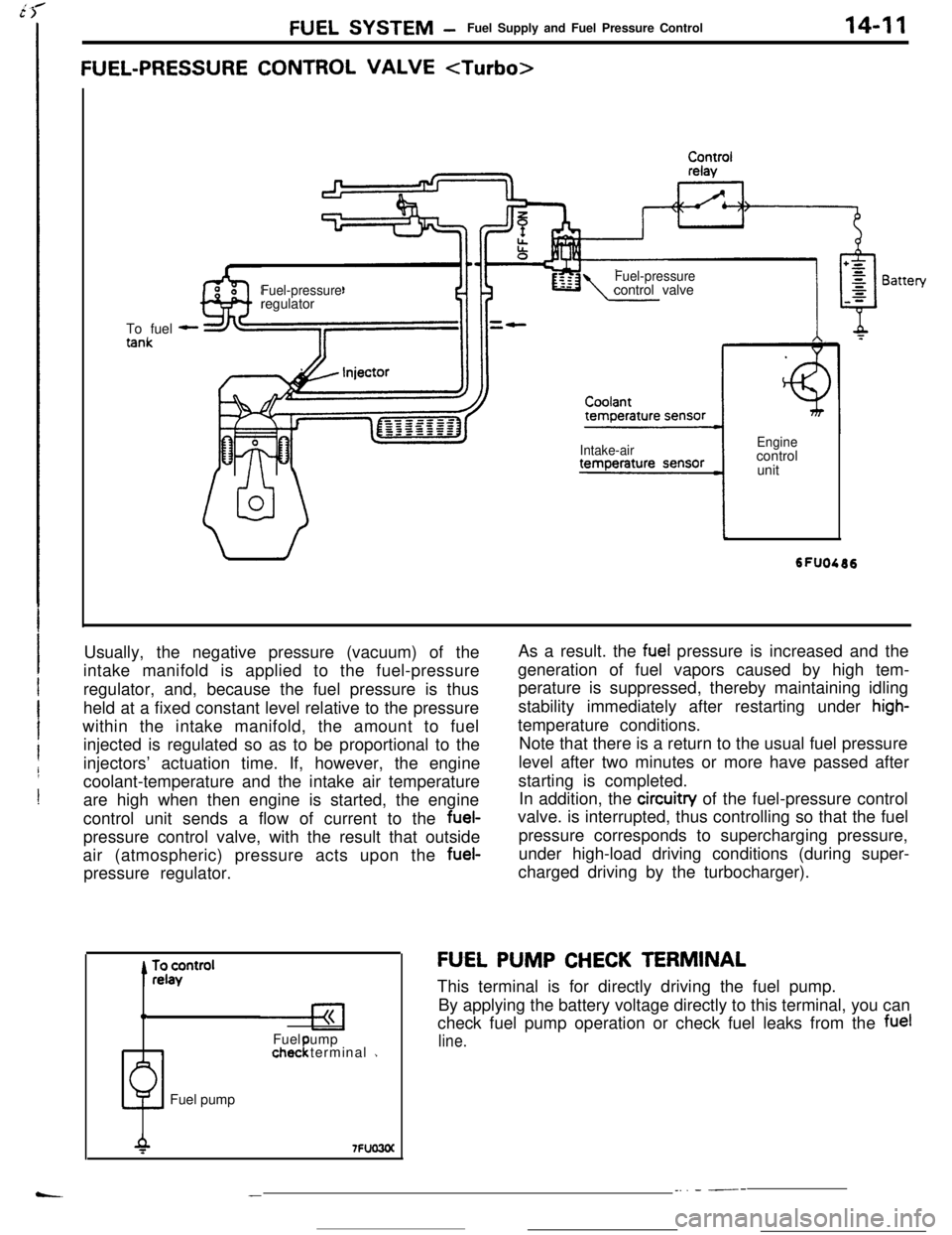
Usually, the negative pressure (vacuum) of the
intake manifold is applied to the fuel-pressure
regulator, and, because the fuel pressure is thus
held at a fixed constant level relative to the pressure
within the intake manifold, the amount to fuel
injected is regulated so as to be proportional to the
injectors’ actuation time. If, however, the engine
coolant-temperature and the intake air temperature
are high when then engine is started, the engine
control unit sends a flow of current to the fuel-
pressure control valve, with the result that outside
air (atmospheric) pressure acts upon the fuel-
pressure regulator.
0Fuel ump
1chec terminal 1!Fuel pumpAs a result. the
fuel pressure is increased and the
generation of fuel vapors caused by high tem-
perature is suppressed, thereby maintaining idling
stability immediately after restarting under
high-temperature conditions.
Note that there is a return to the usual fuel pressure
level after two minutes or more have passed after
starting is completed.
In addition, the circuitry of the fuel-pressure control
valve. is interrupted, thus controlling so that the fuel
pressure corresponds to supercharging pressure,
under high-load driving conditions (during super-
charged driving by the turbocharger).
FU,EL PUMP CHECK TERMINAL
This terminal is for directly driving the fuel pump.
By applying the battery voltage directly to this terminal, you can
check fuel pump operation or check fuel leaks from the
fuel
line.
__. - ---
Page 124 of 391

140’I2FUEL SYSTEM- Intake Air Control
INTAKE AIR CONTROL
GENERAL DESCRIPTION
Rl4oA?, Speed adjusting screwIdle oositionswitch-
Throttle valve
0
+ Bypass air flow
before metenng
Q Bypass air fjow
Iafter metenng
Idle soeed control servo
-?hrottle position sensor
Fast idle air valve
oolant from thermostat case
ITo return pipe6FUO777Control of the volume of intake air is performed by the throttle
valve, the speed adjusting screw, the fast idle air valve and the
idle speed control servo, all of which are mounted on
ttithrottle body.
iControl by idle
w/d c;zk;;fast
hhidle air valve
Speed adjusting screwThrottle valve
m-30~22) of321 sofm 6of140~ 901164
Coolant temperature ‘C (OF)6Fuo!DURING ENGINE WARM UP
The intake air flow during fast idle is controlled by both the wax
actuated air valve which functions. in response to the engine
coolant temperature and the idle speed control servo that is
controlled by the engine control unit.
AFTER ENGINE HAS BEEN WARMED UP
Control of the intake air flow during curb idle (or the control of
curb idle speed) is performed by the idle speed control servo
which in turn is controlled by the engine control unit.
Refer to page 1445 for control of the idle speed control servo.The idle speed can be adjusted. by increasing or decreasing theintake air flow rate with the speed adjusting screw.
The off-idle intake air flow is controlled by the throttle
valve;operation of the accelerator pedal determines the degree that
the throttle valve is open at any particular moment.
-
.?‘h,
. .
Page 125 of 391
FUEL SYSTEM- Intake Air Control
SPECIFICATIONS
ternsThrottle body
Throttle bore diametermm
(in.1Fast idle air valve
TwValve closing temperature
“C (“F)
Idle speed control servo
TypeSpecifications
60 (2.362)
WAX type
Approximately 50
(122)Stepper motor type
FAST IDLE AIR VALVEEngine coolant
LAir valve
Waxpellet
Valve seat
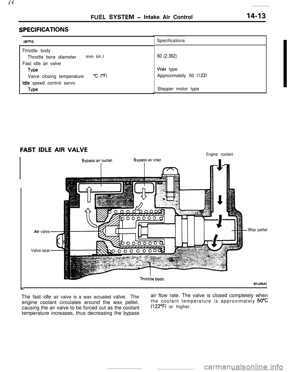
6FUO642The fast idle air valve is a wax actuated valve. The
engine coolant circulates around the wax pellet.
causing the air valve to be forced out as the coolant
temperature increases, thus decreasing the bypassair flow rate. The valve is closed completely when
the coolant temperature is approximately 50°C
(122°F) or higher.
Page 126 of 391
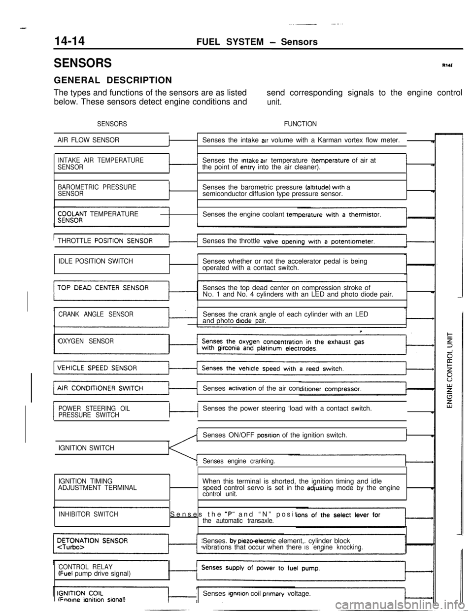
14-14
.._~- ---.FUEL SYSTEM
- Sensors
SENSORSRlUGENERAL DESCRIPTION
The types and functions of the sensors are as listedsend corresponding signals to the engine control
below. These sensors detect engine conditions and
unit.
SENSORSFUNCTION
AIR FLOW SENSOR
fSenses the intake arr volume with a Karman vortex flow meter.
INTAKE AIR TEMPERATURE
SENSORSenses the Intake air temperature (temperature of air at
the point of entry into the air cleaner).I
BAROMETRIC PRESSURE
SENSORISenses the barometric pressure faltrtude) wrth a
semiconductor diffusion type pressure sensor.
$;;OOf;T TEMPERATURESenses the engine coolant tern
THROTTLE
POSITISenses the throttle
tI
IDLE POSITION SWITCHSenses whether or not the accelerator pedal is being
operated with a contact switch.
Senses the top dead center on compression stroke of
NO. 1 and No. 4 cylinders with an LED and photo diode pair.
CRANK ANGLE SENSORSenses the crank angle of each cylinder with an LED
and photo diodepair.
T
OXYGEN SENSORSenses
actrvation of the air con
POWER STEERING OIL
PRESSURE SWITCHc-lSenses the power steering ‘load with a contact switch.
IGNITION SWITCHSenses ON/OFF
posrtion of the ignition switch.I
Senses engine cranking.
,
IGNITION TIMING
ADJUSTMENT TERMINALWhen this terminal is shorted, the ignition timing and idle
speed control servo is set in the adjustrng mode by the enginecontrol unit.
INHIBITOR SWITCHSenses the *P” and “N” positthe automatic transaxle.Senses.
by pieto-electric element,. cylinder block
vibrations that occur when there ISengineknocking.
CONTROL RELAY
(Fuel pump drive signal)
lFnorne ianitron sianal!Senses ignrtton coil prIman/ voltage.
Page 127 of 391
FUEL SYSTEM - Sensors
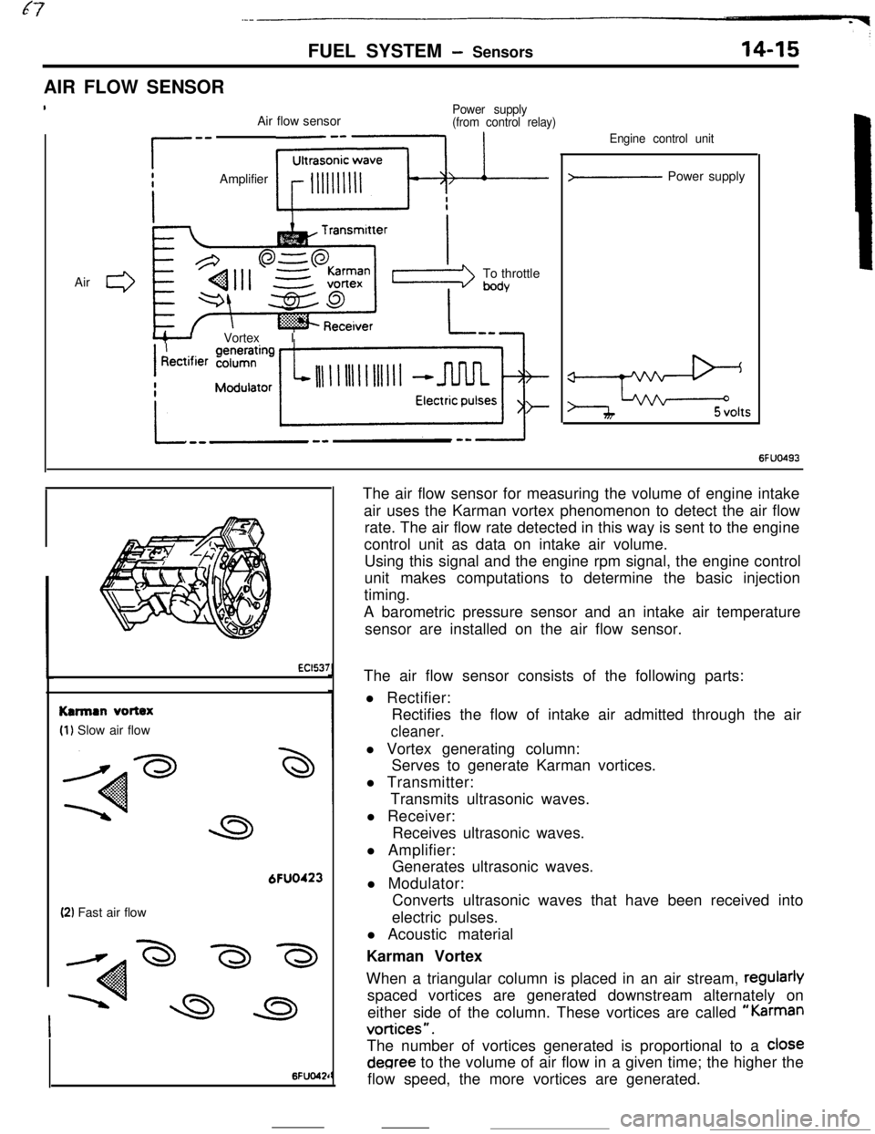
AIR FLOW SENSOR
IAir
0
Power supplyAir flow sensor(from control relay)
r-- Amplifier Few
L+--J Vortex ITo throttle
bodyEngine control unit
>- Power supply
e5 volts
6FUO493
EC1537
Karman vortex
(1) Slow air flow
6FUO423
(2) Fast air flow
6Fuo42rThe air flow sensor for measuring the volume of engine intake
air uses the Karman vortex phenomenon to detect the air flow
rate. The air flow rate detected in this way is sent to the engine
control unit as data on intake air volume.
Using this signal and the engine rpm signal, the engine control
unit makes computations to determine the basic injection
timing.
A barometric pressure sensor and an intake air temperature
sensor are installed on the air flow sensor.
The air flow sensor consists of the following parts:
l Rectifier:
Rectifies the flow of intake air admitted through the air
cleaner.l Vortex generating column:
Serves to generate Karman vortices.
l Transmitter:
Transmits ultrasonic waves.
l Receiver:
Receives ultrasonic waves.
l Amplifier:
Generates ultrasonic waves.
l Modulator:
Converts ultrasonic waves that have been received into
electric pulses.
l Acoustic material
Karman Vortex
When a triangular column is placed in an air stream, regularly
spaced vortices are generated downstream alternately on
either side of the column. These vortices are called
“Karman
vortices”.The number of vortices generated is proportional to a
cloSedegree to the volume of air flow in a given time; the higher the
flow speed, the more vortices are generated.
Page 128 of 391
14-16FUEL SYSTEM - Sensors
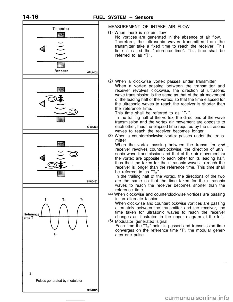
TransmitterMEASUREMENT OF INTAKE AIR FLOW
(1) When there is no air’ flow
No vortices are generated in the absence of air flow.
Therefore, the ultrasonic waves transmitted from the
transmitter take a fixed time to reach the receiver. This
time is called the “reference time”. This time shall be
referred to as
“T”.
Recetver6FUo42!
6FUO426
6f UO42;
TIT1Tl
~tee;ence
9%
T22
Pulses generated by modulator
(2) When a clockwise vortex passes under transmitter
When a vortex passing between the transmitter and
receiver revolves clockwise, the direction of ultrasonic
wave transmission is the same as that of the air movement
of the leading half of the vortex, so that the time elapsed for
the ultrasonic waves to reach the receiver is shorter than
the reference time.
This time shall be referred to as
“T, “.
In the trailing half of the vortex, the directions of the wave
transmission and the vortex air movement are opposite to
each other, thus the elapsed time required by the ultrasonic
waves to reach the receiver becomes longer.
(3) When a counterclockwise vortex passes under the trans-
mitter
When the vortex passing between the transmitter
and-.receiver revolves counterclockwise, the direction of ultr:
sonic wave transmission and that of the air movement
OTthe vortex are opposite to each other for its leading half,
thus the time taken for the ultrasonic waves to reach the
receiver is longer than the reference time. This time shall
be referred to as
“Tz”.In the trailing half of the vortex, the directions of the two
are the same so that the time taken for the ultrasonic
waves to reach the receiver becomes shorter than the
reference time.
(4) When clockwise and counterclockwise vortices are passing
in an alternate fashion
When clockwise and counterclockwise vortices are passing
alternately between the transmitter and the receiver, the
time taken for ultrasonic waves to reach the receiver
changes as illustrated in the upper diagram at the left.
(5) Modulator generated signal
Each time the “T2” point is passed and transmission time
converges on the reference time “T”, the modular gener-
ates one pulse.
-
Page 129 of 391
FUEL SYSTEM - SensorsWhen more air
is drawnT1
Pulses generated by modulatorWhen
less air is drawn6FUO42
TI
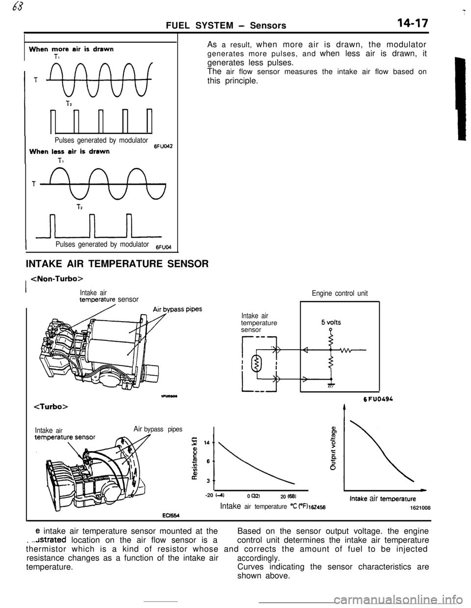
IPulses generated by modulator6FuWAs a result, when more air is drawn, the modulator
generates more pulses, and when less air is drawn, it
generates less pulses.
The air flow sensor measures the intake air flow based on
this principle.
INTAKE AIR TEMPERATURE SENSOR
I
Intake airAir bypass pipesEC654
Intake airtemperature
sensor
s-v
r .==
II
fi ;=---
Engine control unit
6 FUOOSL-20
I410 (32)20 I6913
Intake air temoerature
Intake air temperature “C (‘Fl 1624581621008
e intake air temperature sensor mounted at theBased on the sensor output voltage. the engine
.
..Jstrated location on the air flow sensor is acontrol unit determines the intake air temperature
thermistor which is a kind of resistor whose and corrects the amount of fuel to be injected
resistance changes as a function of the intake air
accordingly.temperature.Curves indicating the sensor characteristics are
shown above.
Page 130 of 391
14-18FUEL SYSTEM - Sensors
tBAROMETRIC PRESSURE SENSOR
Barometnc rxessure sensor
EC1537
Barometncpressure sensor
Enginecontrol unit
1OFUO576
/
760 (30)Barometric pressure mmHg
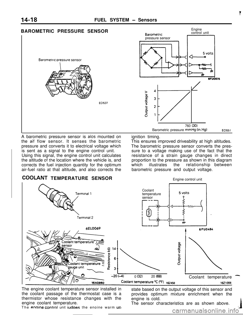
(in.Hg)EC1551A barometric pressure sensor is
alas mounted on
the
aif flow sensor. It senses the barometric
pressure and converts it to electrical voltage which
is sent as a signal to the engine control unit.
Using this signal, the engine control unit calculates
the altitude
of.the location where the vehicle is, and
corrects the fuel injection quantity for the optimum
air-fuel ratio at that altitude, and also corrects the
COOLANT TEMPERATURE SENSOR
Terminal 26EL0069ignition timing.
This ensures improved driveability at high altitudes.
The barometric pressure sensor converts the pres-
sure to a voltage making use of the fact that the
resistance of a strain gauge changes in direct
proportion to the pressure as shown in this diagram
which
illustratestherelationship between
barometric pressure and output voltage.
Engine control unit
Coolanttemperature
sensor
-a
Tg-I
h-esI
*
LizIdr
tSFUOLSL
L0 (32120 (68)Coolant temperature -The engine coolant temperature sensor installed in
the coolant passage of the thermostat case is a
thermistor whose resistance changes with the
engine coolant temperature.
The
annine control unit iudoes the enoine warm UDstate based on the output voltage of this sensor and
provides optimum mixture enrichment when the
engine is cold.
The sensor characteristics are as shown above..:I