MITSUBISHI ENDEAVOR 2004 Service Repair Manual
Manufacturer: MITSUBISHI, Model Year: 2004, Model line: ENDEAVOR, Model: MITSUBISHI ENDEAVOR 2004Pages: 3870, PDF Size: 98.47 MB
Page 1091 of 3870
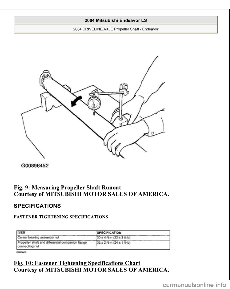
Fig. 9: Measuring Propeller Shaft Runout
Courtesy of MITSUBISHI MOTOR SALES OF AMERICA.
SPECIFICATIONS FASTENER TIGHTENING SPECIFICATIONS Fig. 10: Fastener Tightening Specifications Chart
Courtes
y of MITSUBISHI MOTOR SALES OF AMERICA
.
2004 Mitsubishi Endeavor LS
2004 DRIVELINE/AXLE Propeller Shaft - Endeavor
Page 1092 of 3870
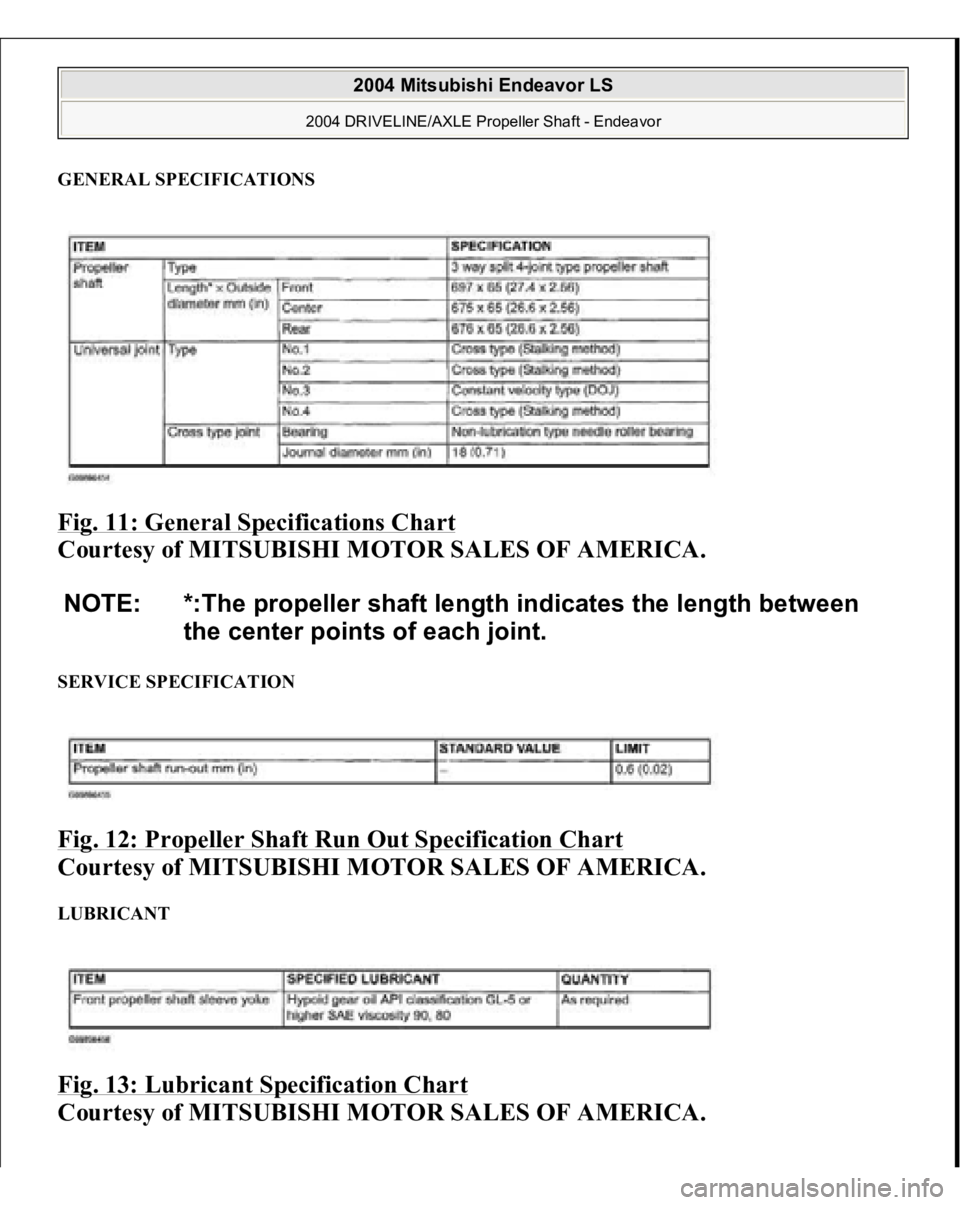
GENERAL SPECIFICATIONS Fig. 11: General Specifications Chart
Courtesy of MITSUBISHI MOTOR SALES OF AMERICA.
SERVICE SPECIFICATION Fig. 12: Propeller Shaft Run Out Specification Chart
Courtesy of MITSUBISHI MOTOR SALES OF AMERICA.
LUBRICANT Fig. 13: Lubricant Specification Chart
Courtesy of MITSUBISHI MOTOR SALES OF AMERICA.
NOTE: *:The propeller shaft length indicates the length between
the center points of each joint.
2004 Mitsubishi Endeavor LS
2004 DRIVELINE/AXLE Propeller Shaft - Endeavor
Page 1093 of 3870
2004 MITSUBISH
I
Endeavor
BUZZERS, RELAYS & TIMERS BUZZERS, RELAYS & TIMERS LOCATION CIRCUIT PROTECTION DEVICES CIRCUIT PROTECTION DEVICES LOCATION Component
Location
A/C Compressor Clutch Relay
On engine compartment relay box. See
Fig. 38
.
A/T Control Relay
On engine compartment relay box.Fig.
38 .
Defogger Relay
On junction block. See Fig. 39
.
Fan Control Relay
On engine compartment relay box. See
Fig. 38
.
Fog Light Relay
On engine compartment relay box. See
Fig. 38
.
Front Blower Relay
On junction block. See Fig. 39
.
Fuel Pump Relay (1)
On junction block. See Fig. 39
.
Fuel Pump Relay (2)
On junction block. See Fig. 39
.
Heated Seat Relay
On junction block. See Fig. 39
.
Horn Relay
On engine compartment relay box. See
Fig. 38
.
MFI Relay
On engine compartment relay box. See
Fig. 38
.
Power Window Relay
On junction block. See Fig. 39
.
Rear Blower Relay
On junction block.Fig. 39
.
Throttle Actuator Control Motor Relay
On engine compartment relay box. See
Fig. 38
.
Component
Location
Engine Compartment Relay Box
Left side of engine compartment.Fi
g.
2004 Mitsubishi Endeavor LS
2004 MITSUBISHI Endeavor
2004 Mitsubishi Endeavor LS
2004 MITSUBISHI Endeavor
Page 1094 of 3870
CONTROL UNITS CONTROL UNITS LOCATION
17 .
Fusible Link No. 1 - 5
On engine compartment relay box.Fi
g.
17 .
Fusible Link No. 26
At positive battery terminal
connection.Fig. 16
.
Junction Block
Left end of dash. See Fig. 19
.
Component
Location
ABS ECU
At right rear corner of engine
compartment. See Fig. 1
.
ABS/TCL ECU
At right rear corner of engine
compartment. See Fig. 1
.
A/C ECU
Center of dash. See Fig. 6
.
ACS/TCL ECU
At right rear corner of engine
compartment. See Fig. 1
.
Column ECU
Near top of steering column. See Fi
g. 8 .
Combination Meter ECU
In instrument cluster. See Fig. 5
.
ETACS ECU
Behind left side of dash, near junction
block.Fig. 7
.
Fan Control Module
Left front of engine compartment. See
Fig. 3
.
Front ECU
On engine compartment relay box.Fi
g. 2 .
Immobilizer ECU (From January
2004)
Center of dash.Fig. 9
.
Immobilizer ECU (Up To December
2003)
Next to steering column. See Fig. 10
.
Occupant Classification ECU (From
December 2004)
Under left front seat.Fig. 12
.
Powertrain Control Modul
e
Left front of en
gine com
partment.Fi
g.
2004 Mitsubishi Endeavor LS
2004 MITSUBISHI Endeavor
Page 1095 of 3870

MOTORS MOTORS LOCATION SENDING UNITS & SENSORS SENDING UNITS & SENSORS LOCATION
4 .
Power Window Main Switch CPU
Integral to power window main switch.
See Fig. 15
.
SRS ECU
Under front of center console.Fig. 14
.
Sunroof ECU
At front of sunroof opening.Fig. 13
.
Component
Location
Door Lock Actuator (Left Front) (E-
20)
Rear of left front door.Fig. 77
.
Door Lock Actuator (Left Rear) (E-13)
Rear of left rear door.Fig. 77
.
Door Lock Actuator (Right Front) (E-
03)
Rear of right front door.Fig. 77
.
Door Lock Actuator (Right Rear) (E-
07)
Rear of right rear door.Fig. 77
.
Fuel Pump Module
In top of fuel tank.Fig. 64
.
Liftgate Actuator (F-11)
Lower center of liftgate. See Fig. 88
.
Power Steering Oil Pump
Lower right side of engine
compartment. See Fig. 36
.
Rear Blower Motor (C-20)
Rear of center console.Fig. 76
.
Rear Washer Motor (A-26)
In washer tank assembly.Fig. 79
.
Sunroof Motor Assembly
Right front of roof. See Fig. 62
.
Windshield Washer Motor (A-27)
In washer tank assembly.Fig. 79
.
Windshield Wiper Motor (A-03)
On left side of firewall.Fig. 79
.
Component
Location
ABS G Sensor Or G & Yaw Rate
Sensor
Under center console. See Fig. 67
.
Acceleration Pedal Position
Above accelerator pedal.Fig. 59
.
2004 Mitsubishi Endeavor LS
2004 MITSUBISHI Endeavor
Page 1096 of 3870
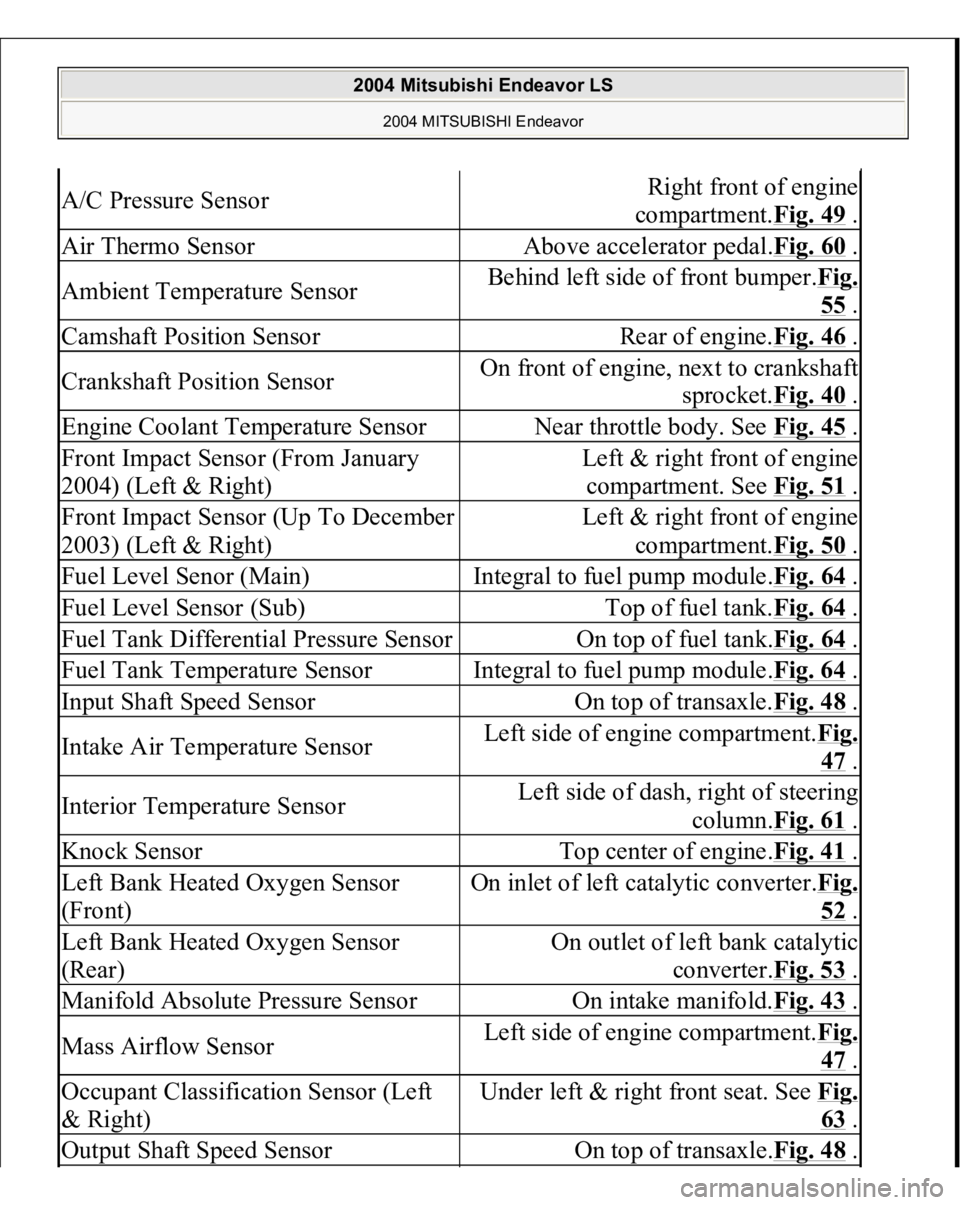
A/C Pressure Sensor
Right front of engine
compartment.Fig. 49
.
Air Thermo Sensor
Above accelerator pedal.Fig. 60
.
Ambient Temperature Sensor
Behind left side of front bumper.Fig.
55 .
Camshaft Position Sensor
Rear of engine.Fig. 46
.
Crankshaft Position Sensor
On front of engine, next to crankshaft
sprocket.Fig. 40
.
Engine Coolant Temperature Sensor
Near throttle body. See Fig. 45
.
Front Impact Sensor (From January
2004) (Left & Right)
Left & right front of engine
compartment. See Fig. 51
.
Front Impact Sensor (Up To December
2003) (Left & Right)
Left & right front of engine
compartment.Fig. 50
.
Fuel Level Senor (Main)
Integral to fuel pump module.Fig. 64
.
Fuel Level Sensor (Sub)
Top of fuel tank.Fig. 64
.
Fuel Tank Differential Pressure Sensor
On top of fuel tank.Fig. 64
.
Fuel Tank Temperature Sensor
Integral to fuel pump module.Fig. 64
.
Input Shaft Speed Sensor
On top of transaxle.Fig. 48
.
Intake Air Temperature Sensor
Left side of engine compartment.Fi
g.
47 .
Interior Temperature Sensor
Left side of dash, right of steering
column.Fig. 61
.
Knock Sensor
Top center of engine.Fig. 41
.
Left Bank Heated Oxygen Sensor
(Front)
On inlet of left catalytic converter.Fi
g.
52 .
Left Bank Heated Oxygen Sensor
(Rear)
On outlet of left bank catalytic
converter.Fig. 53
.
Manifold Absolute Pressure Sensor
On intake manifold.Fig. 43
.
Mass Airflow Sensor
Left side of engine compartment.Fi
g.
47 .
Occupant Classification Sensor (Left
& Right)
Under left & right front seat. See Fi
g.
63 .
Output Shaft Speed Sensor
On top of transaxle.Fig. 48
.
2004 Mitsubishi Endeavor LS
2004 MITSUBISHI Endeavor
Page 1097 of 3870
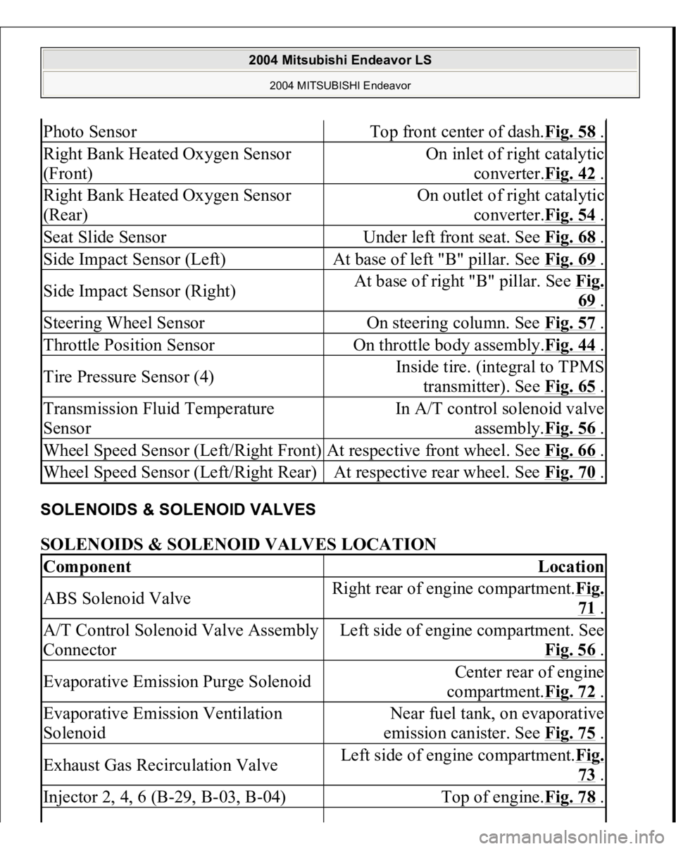
SOLENOIDS & SOLENOID VALVES SOLENOIDS & SOLENOID VALVES LOCATION Photo Sensor
Top front center of dash.Fig. 58
.
Right Bank Heated Oxygen Sensor
(Front)
On inlet of right catalytic
converter.Fig. 42
.
Right Bank Heated Oxygen Sensor
(Rear)
On outlet of right catalytic
converter.Fig. 54
.
Seat Slide Sensor
Under left front seat. See Fig. 68
.
Side Impact Sensor (Left)
At base of left "B" pillar. See Fig. 69
.
Side Impact Sensor (Right)
At base of right "B" pillar. See Fig.
69 .
Steering Wheel Sensor
On steering column. See Fig. 57
.
Throttle Position Sensor
On throttle body assembly.Fig. 44
.
Tire Pressure Sensor (4)
Inside tire. (integral to TPMS
transmitter). See Fig. 65
.
Transmission Fluid Temperature
Sensor
In A/T control solenoid valve
assembly.Fig. 56
.
Wheel Speed Sensor (Left/Right Front)
At respective front wheel. See Fig. 66
.
Wheel Speed Sensor (Left/Right Rear)
At respective rear wheel. See Fig. 70
.
Component
Location
ABS Solenoid Valve
Right rear of engine compartment.Fig.
71 .
A/T Control Solenoid Valve Assembly
Connector
Left side of engine compartment. See
Fig. 56
.
Evaporative Emission Purge Solenoid
Center rear of engine
compartment.Fig. 72
.
Evaporative Emission Ventilation
Solenoid
Near fuel tank, on evaporative
emission canister. See Fig. 75
.
Exhaust Gas Recirculation Valve
Left side of engine compartment.Fig.
73 .
Injector 2, 4, 6 (B-29, B-03, B-04)
Top of engine.Fig. 78
.
2004 Mitsubishi Endeavor LS
2004 MITSUBISHI Endeavor
Page 1098 of 3870
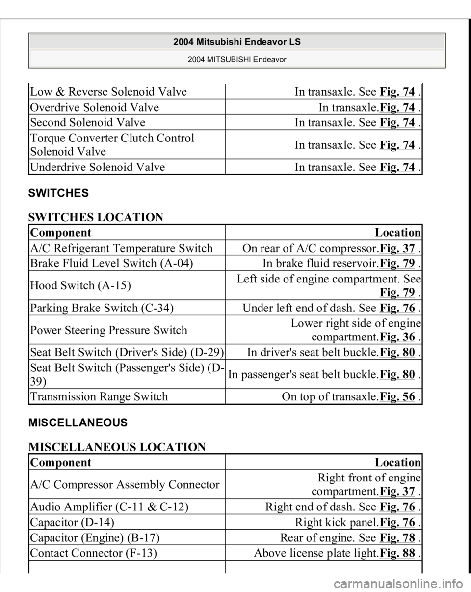
SWITCHES SWITCHES LOCATION MISCELLANEOUS MISCELLANEOUS LOCATION Low & Reverse Solenoid Valve
In transaxle. See Fig. 74
.
Overdrive Solenoid Valve
In transaxle.Fig. 74
.
Second Solenoid Valve
In transaxle. See Fig. 74
.
Torque Converter Clutch Control
Solenoid Valve
In transaxle. See Fig. 74
.
Underdrive Solenoid Valve
In transaxle. See Fig. 74
.
Component
Location
A/C Refrigerant Temperature Switch
On rear of A/C compressor.Fig. 37
.
Brake Fluid Level Switch (A-04)
In brake fluid reservoir.Fig. 79
.
Hood Switch (A-15)
Left side of engine compartment. See
Fig. 79
.
Parking Brake Switch (C-34)
Under left end of dash. See Fig. 76
.
Power Steering Pressure Switch
Lower right side of engine
compartment.Fig. 36
.
Seat Belt Switch (Driver's Side) (D-29)
In driver's seat belt buckle.Fig. 80
.
Seat Belt Switch (Passenger's Side) (D-
39)
In passenger's seat belt buckle.Fig. 80
.
Transmission Range Switch
On top of transaxle.Fig. 56
.
Component
Location
A/C Compressor Assembly Connector
Right front of engine
compartment.Fig. 37
.
Audio Amplifier (C-11 & C-12)
Right end of dash. See Fig. 76
.
Capacitor (D-14)
Right kick panel.Fig. 76
.
Capacitor (Engine) (B-17)
Rear of engine. See Fig. 78
.
Contact Connector (F-13)
Above license plate light.Fig. 88
.
2004 Mitsubishi Endeavor LS
2004 MITSUBISHI Endeavor
Page 1099 of 3870
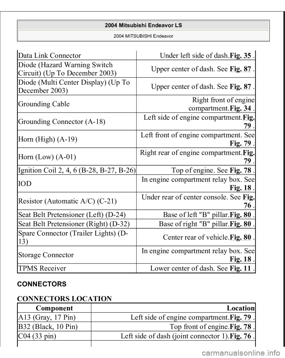
CONNECTORS CONNECTORS LOCATION Data Link Connector
Under left side of dash.Fig. 35
.
Diode (Hazard Warning Switch
Circuit) (Up To December 2003)
Upper center of dash. See Fig. 87
.
Diode (Multi Center Display) (Up To
December 2003)
Upper center of dash. See Fig. 87
.
Grounding Cable
Right front of engine
compartment.Fig. 34
.
Grounding Connector (A-18)
Left side of engine compartment.Fig.
79 .
Horn (High) (A-19)
Left front of engine compartment. See
Fig. 79
.
Horn (Low) (A-01)
Right rear of engine compartment.Fi
g.
79 .
Ignition Coil 2, 4, 6 (B-28, B-27, B-26)
Top of engine. See Fig. 78
.
IOD
In engine compartment relay box. See
Fig. 18
.
Resistor (Automatic A/C) (C-21)
Under rear of center console. See Fi
g.
76 .
Seat Belt Pretensioner (Left) (D-24)
Base of left "B" pillar.Fig. 80
.
Seat Belt Pretensioner (Right) (D-32)
Base of right "B" pillar.Fig. 80
.
Spare Connector (Trailer Lights) (D-
13)
Center rear of vehicle.Fig. 80
.
Storage Connector
In engine compartment relay box. See
Fig. 18
.
TPMS Receiver
Lower center of dash. See Fig. 11
.
Component
Location
A13 (Gray, 17 Pin)
Left side of engine compartment.Fig. 79
.
B32 (Black, 10 Pin)
Top front of engine.Fig. 78
.
C04 (33 pin)
Left side of dash (joint connector 1).Fig. 76
.
2004 Mitsubishi Endeavor LS
2004 MITSUBISHI Endeavor
Page 1100 of 3870
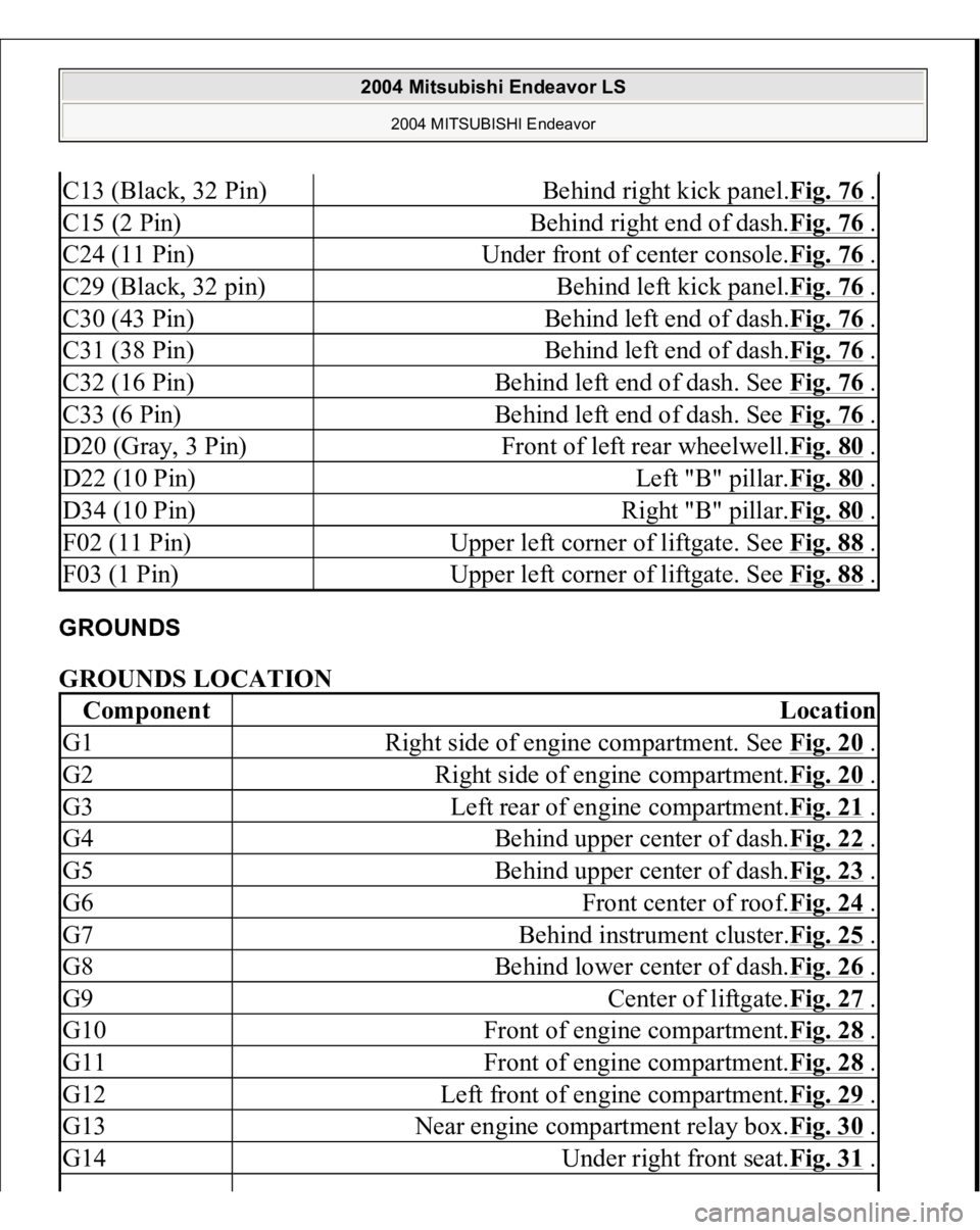
GROUNDS GROUNDS LOCATION C13 (Black, 32 Pin)
Behind right kick panel.Fig. 76
.
C15 (2 Pin)
Behind right end of dash.Fig. 76
.
C24 (11 Pin)
Under front of center console.Fig. 76
.
C29 (Black, 32 pin)
Behind left kick panel.Fig. 76
.
C30 (43 Pin)
Behind left end of dash.Fig. 76
.
C31 (38 Pin)
Behind left end of dash.Fig. 76
.
C32 (16 Pin)
Behind left end of dash. See Fig. 76
.
C33 (6 Pin)
Behind left end of dash. See Fig. 76
.
D20 (Gray, 3 Pin)
Front of left rear wheelwell.Fig. 80
.
D22 (10 Pin)
Left "B" pillar.Fig. 80
.
D34 (10 Pin)
Right "B" pillar.Fig. 80
.
F02 (11 Pin)
Upper left corner of liftgate. See Fig. 88
.
F03 (1 Pin)
Upper left corner of liftgate. See Fig. 88
.
Component
Location
G1
Right side of engine compartment. See Fig. 20
.
G2
Right side of engine compartment.Fig. 20
.
G3
Left rear of engine compartment.Fig. 21
.
G4
Behind upper center of dash.Fig. 22
.
G5
Behind upper center of dash.Fig. 23
.
G6
Front center of roof.Fig. 24
.
G7
Behind instrument cluster.Fig. 25
.
G8
Behind lower center of dash.Fig. 26
.
G9
Center of liftgate.Fig. 27
.
G10
Front of engine compartment.Fig. 28
.
G11
Front of engine compartment.Fig. 28
.
G12
Left front of engine compartment.Fig. 29
.
G13
Near engine compartment relay box.Fig. 30
.
G14
Under right front seat.Fig. 31
.
2004 Mitsubishi Endeavor LS
2004 MITSUBISHI Endeavor