MITSUBISHI ENDEAVOR 2004 Service Repair Manual
ENDEAVOR 2004
MITSUBISHI
MITSUBISHI
https://www.carmanualsonline.info/img/19/57105/w960_57105-0.png
MITSUBISHI ENDEAVOR 2004 Service Repair Manual
Trending: seat adjustment, steering, interval, air bleeding, Gasoline, wiper fluid, oil dipstick
Page 1081 of 3870
kg/cm
2 )
ThermostatStarts To Open
187-193°F (86.5-89.5°
C)
Fully Opens
212°F (100°C)
2004 Mitsubishi Endeavor Limited
2004 ENGINE COOLING Specifications & Drive Belt Routing - Endeavor
Page 1082 of 3870
2004 DRIVELINE/AXL
E
Propeller Shaft - Endeavor
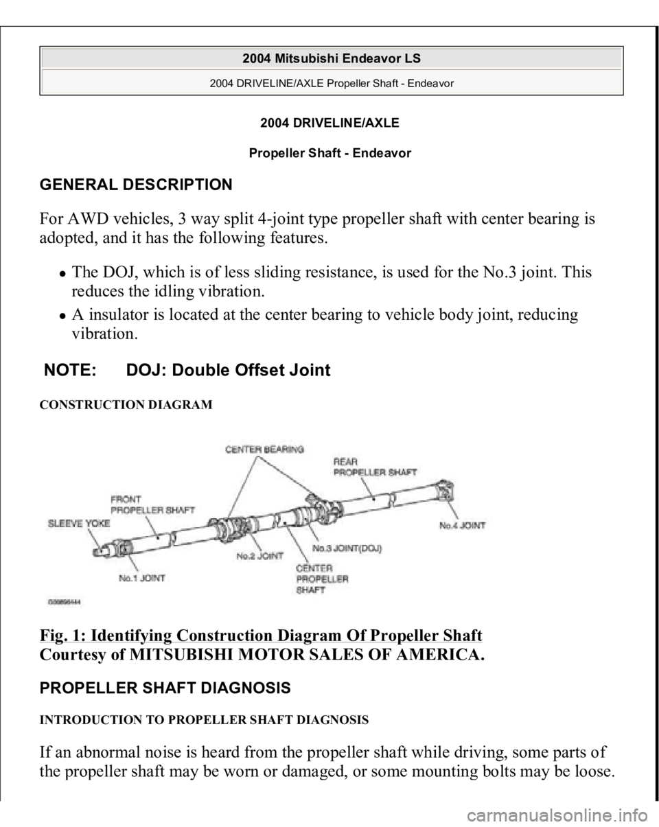
GENERAL DESCRIPTION For AWD vehicles, 3 way split 4-joint type propeller shaft with center bearing is
adopted, and it has the following features.
The DOJ, which is of less sliding resistance, is used for the No.3 joint. This
reduces the idling vibration. A insulator is located at the center bearing to vehicle body joint, reducing
vibration.
CONSTRUCTION DIAGRAM Fig. 1: Identifying Construction Diagram Of Propeller Shaft
Courtesy of MITSUBISHI MOTOR SALES OF AMERICA.
PROPELLER SHAFT DIAGNOSIS INTRODUCTION TO PROPELLER SHAFT DIAGNOSIS If an abnormal noise is heard from the propeller shaft while driving, some parts of
the
propeller shaft ma
y be worn or dama
ged, or some mountin
g bolts ma
y be loose.
NOTE: DOJ: Double Offset Joint
2004 Mitsubishi Endeavor LS
2004 DRIVELINE/AXLE Propeller Shaft - Endeavor
2004 Mitsubishi Endeavor LS
2004 DRIVELINE/AXLE Propeller Shaft - Endeavor
Page 1083 of 3870

PROPELLER SHAFT DIAGNOSTIC TROUBLESHOOTING STRATEGYUse these steps to plan your diagnostic strategy. If you follow them carefully, you
will be sure that you have exhausted all of the possible ways to find a propeller
shaft fault.
1. Gather information from the customer.
2. Verify that the condition described by the customer exists.
3. Find the malfunction by following the Symptom Chart.
4. Verify malfunction is eliminated. SYMPTOM CHART Fig. 2: Propeller Shaft Troubleshooting Symptom Chart
Courtesy of MITSUBISHI MOTOR SALES OF AMERICA.
SYMPTOM PROCEDURES INSPECTION PROCEDURE 1: Noise at Start DIAGNOSIS
STEP 1. Check if the propeller shaft and differential companion flange
connecting nuts and the center bearing mounting nuts are loose.
Connecting nuts tightening torque: 32 +/- 2 N.m (24 +/- 1 ft-lb)
Mounting nuts tightening torque: 30 +/- 4 N.m (22 +/- 3 ft-lb)
Q: Are the connecting nuts and mounting nuts tightened to the specified
torque?
YES: Go to Ste
p 2.
2004 Mitsubishi Endeavor LS
2004 DRIVELINE/AXLE Propeller Shaft - Endeavor
Page 1084 of 3870
NO: Tighten the connecting nuts and mounting nuts to the specified
torque. Then go to Step 3 .
STEP 2. Check the sleeve yoke's spline of front propeller shaft for wear.
Q: Is wear apparent?
YES: Replace the propeller shaft. Then go to Step 3.
NO: Go to Step 3.
STEP 3. Retest the system.
Q: Is the abnormal noise eliminated?
YES: The procedure is complete.
NO: Recheck from Step 1 .
INSPECTION PROCEDURE 2: Noise and Vibration at High Speed DIAGNOSIS
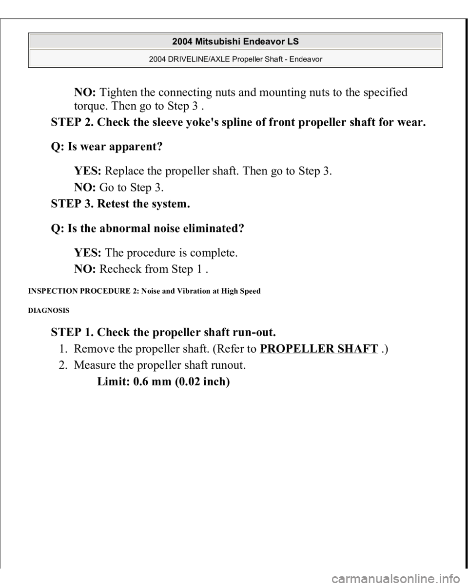
STEP 1. Check the propeller shaft run-out.
1. Remove the propeller shaft. (Refer to PROPELLER SHAFT
.)
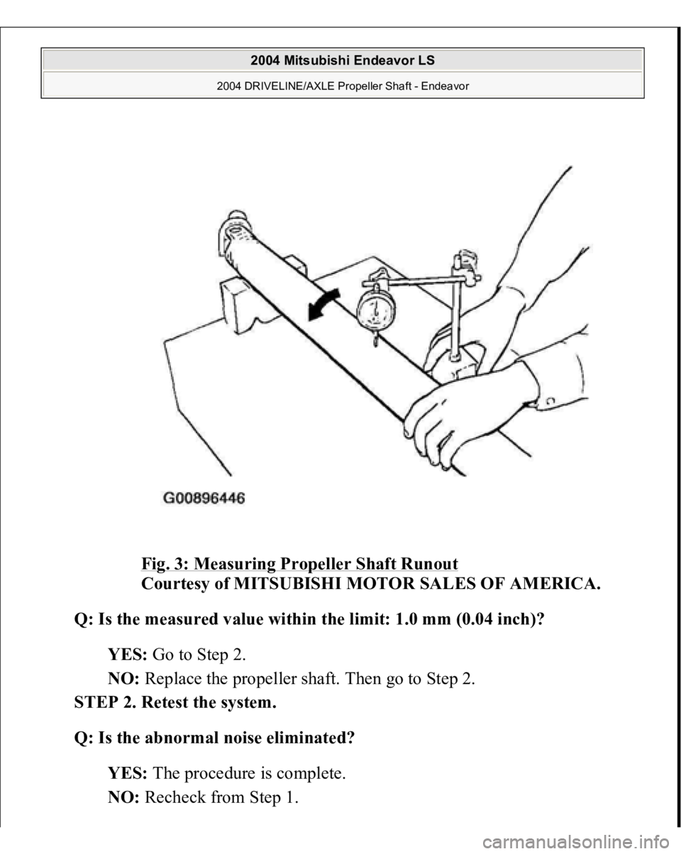
2. Measure the propeller shaft runout.
Limit: 0.6 mm (0.02 inch)
2004 Mitsubishi Endeavor LS
2004 DRIVELINE/AXLE Propeller Shaft - Endeavor
Page 1085 of 3870
Fig. 3: Measuring Propeller Shaft Runout
Courtesy of MITSUBISHI MOTOR SALES OF AMERICA.
Q: Is the measured value within the limit: 1.0 mm (0.04 inch)?
YES: Go to Step 2.
NO: Replace the propeller shaft. Then go to Step 2.
STEP 2. Retest the system.
Q: Is the abnormal noise eliminated?
YES: The procedure is complete.
NO: Recheck from Ste
p 1.
2004 Mitsubishi Endeavor LS
2004 DRIVELINE/AXLE Propeller Shaft - Endeavor
Page 1086 of 3870
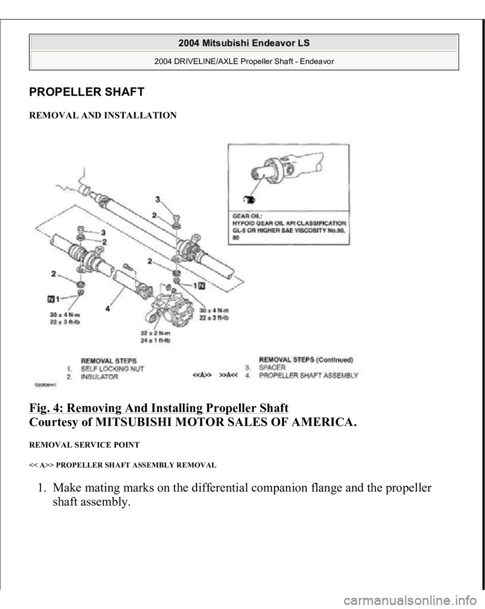
PROPELLER SHAFT REMOVAL AND INSTALLATION Fig. 4: Removing And Installing Propeller Shaft
Courtesy of MITSUBISHI MOTOR SALES OF AMERICA.
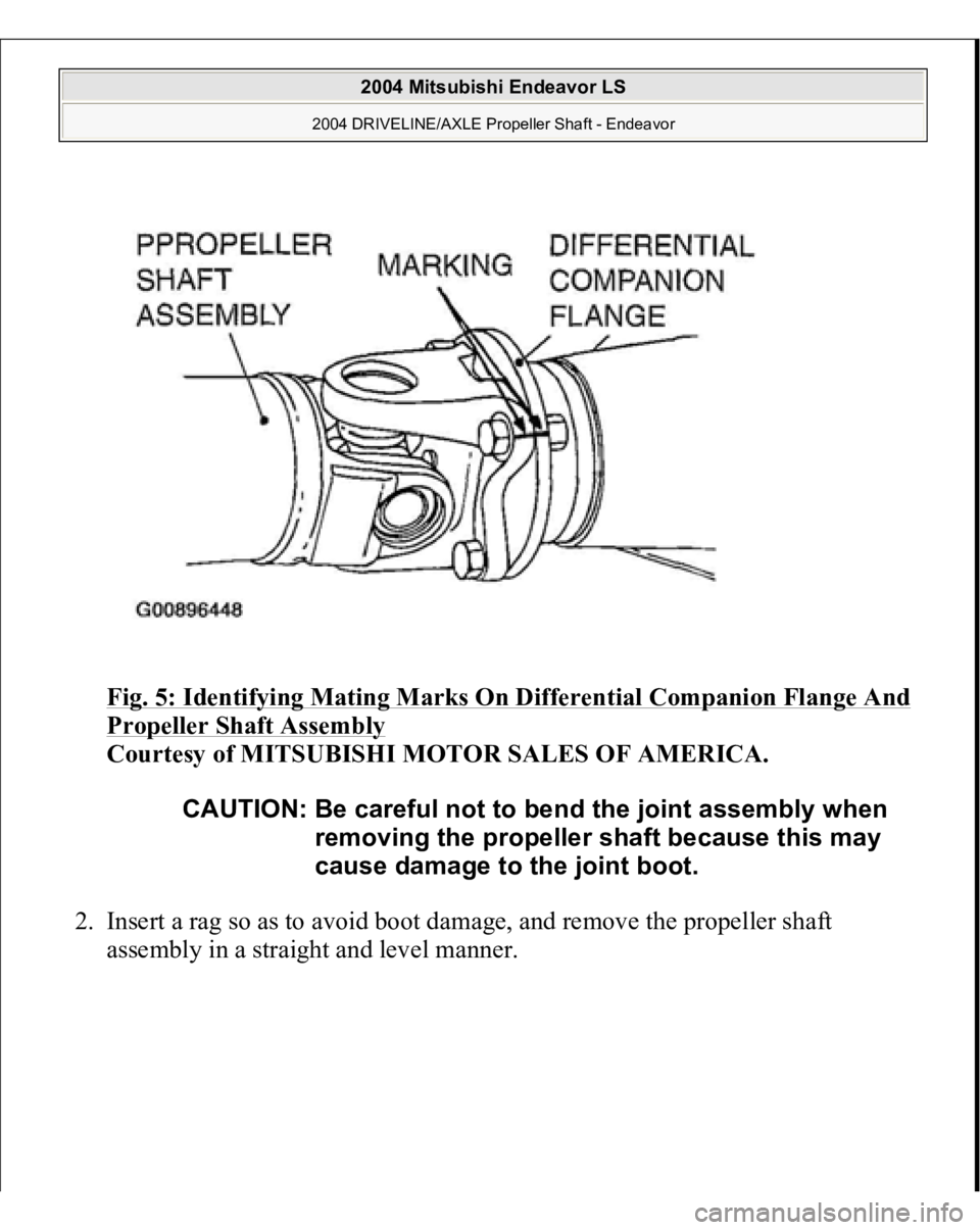
REMOVAL SERVICE POINT << A>> PROPELLER SHAFT ASSEMBLY REMOVAL 1. Make mating marks on the differential companion flange and the propeller
shaft assembl
y.
2004 Mitsubishi Endeavor LS
2004 DRIVELINE/AXLE Propeller Shaft - Endeavor
Page 1087 of 3870
Fig. 5: Identifying Mating Marks On Differential Companion Flange And Propeller Shaft Assembly
Courtesy of MITSUBISHI MOTOR SALES OF AMERICA.
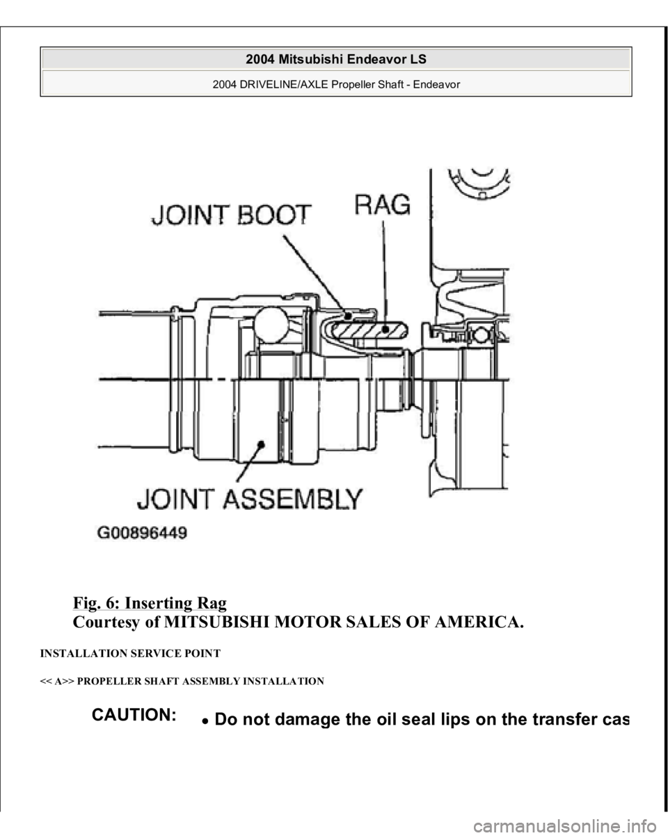
2. Insert a rag so as to avoid boot damage, and remove the propeller shaft
assembly in a straight and level manner.
CAUTION: Be careful not to bend the joint assembly when
removing the propeller shaft because this may
cause damage to the joint boot.
2004 Mitsubishi Endeavor LS
2004 DRIVELINE/AXLE Propeller Shaft - Endeavor
Page 1088 of 3870
Fig. 6: Inserting Rag
Courtesy of MITSUBISHI MOTOR SALES OF AMERICA.
INSTALLATION SERVICE POINT << A>> PROPELLER SHAFT ASSEMBLY INSTALLATION
CAUTION:
Do not dama
ge the oil seal lips on the transfer ca
s
2004 Mitsubishi Endeavor LS
2004 DRIVELINE/AXLE Propeller Shaft - Endeavor
Page 1089 of 3870
If reusing the propeller shaft, align the mating marks of differential companion
flan
ge and
propeller shaft assembl
y to install.
Fig. 7: Locating Oil Seal Lips On Transfer Case
Courtes
y of MITSUBISHI MOTOR SALES OF AME
R
Remove oil and grease from the threads of the
mounting bolts and nuts before ti
ghtenin
g, or the
y
loosen. Be careful not to bend the
joint portion when rem
o
the propeller shaft, because this will damage the j
o
boot.
2004 Mitsubishi Endeavor LS
2004 DRIVELINE/AXLE Propeller Shaft - Endeavor
Page 1090 of 3870
Fig. 8: Aligning Mating Marks Of Differential Companion Flange And Propeller Shaft Assembly
Courtesy of MITSUBISHI MOTOR SALES OF AMERICA.
INSPECTION
Check the sleeve yoke and center yoke for wear, damage or cracks. Check the propeller shaft for bends, twisting or damage. Check the universal joint for smooth operation in all directions. Check the center bearing for smooth movement.
PROPELLER SHAFT RUNOUT
Limit: 0.6 mm (0.02 inch)
2004 Mitsubishi Endeavor LS
2004 DRIVELINE/AXLE Propeller Shaft - Endeavor
Trending: oil change, Battery terminals, cover, oil temperature, clock setting, air suspension, USB port

