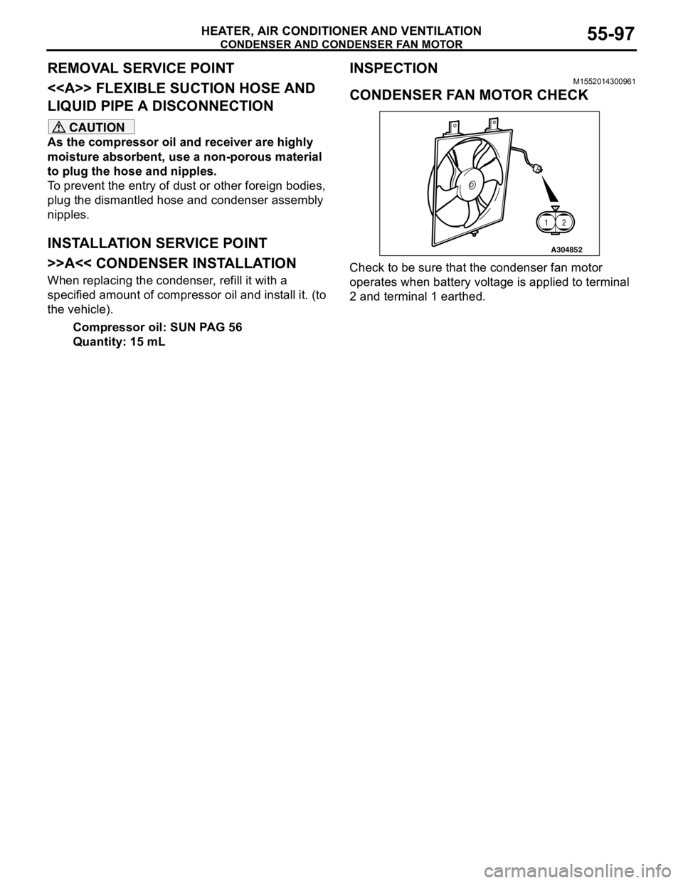
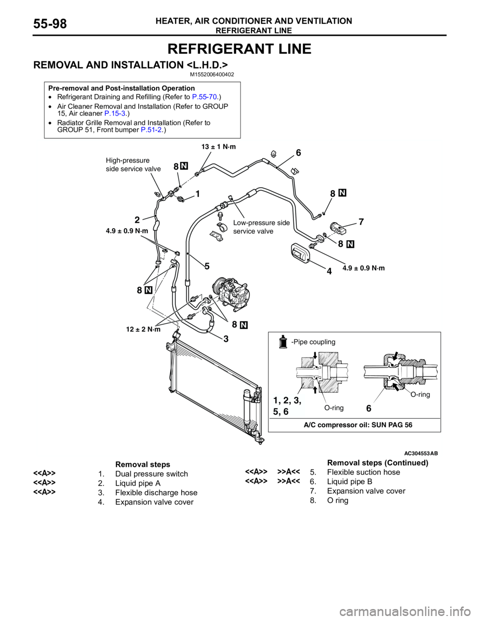
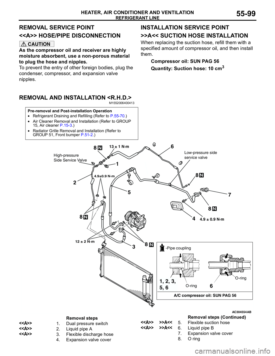
MITSUBISHI LANCER 2005 Workshop Manual
LANCER 2005
MITSUBISHI
MITSUBISHI
https://www.carmanualsonline.info/img/19/57321/w960_57321-0.png
MITSUBISHI LANCER 2005 Workshop Manual
Trending: differential, engine coolant, rear, Body, air condition, front, run flat
Page 581 of 788
Page 582 of 788
Page 583 of 788
Page 584 of 788
Page 585 of 788
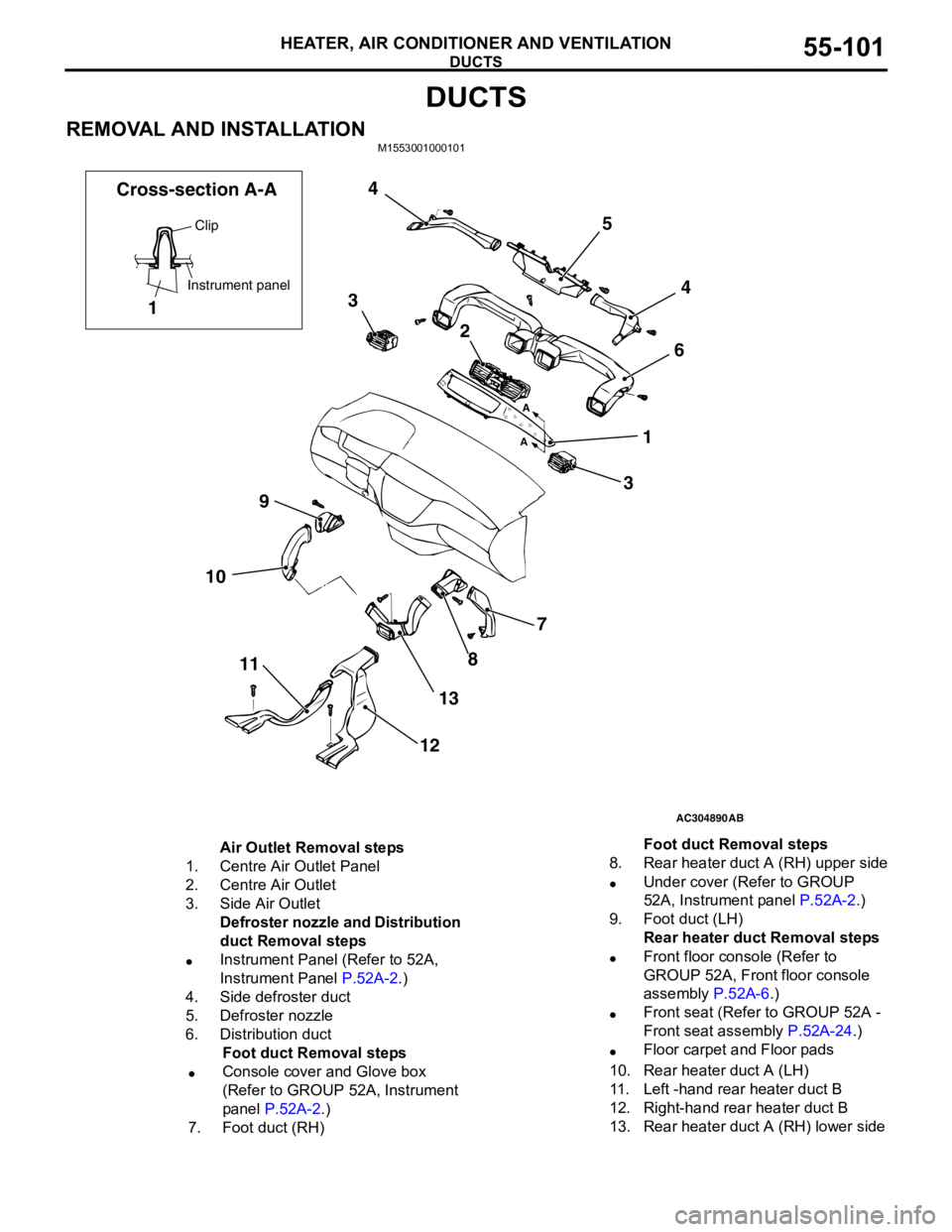
DUCTS
HEATER, AIR CONDITIONER AND VENTILATION55-101
DUCTS
REMOVAL AND INSTALLATIONM1553001000101
AC304890
7
8
13
12 11 109364 5 4
3
2
1
AB A
A
Clip
Instrument panel
1 Cross-section A-A
Air Outlet Removal steps
1. Centre Air Outlet Panel
2. Centre Air Outlet
3. Side Air Outlet
Defroster nozzle and Distribution
duct Removal steps
•Instrument Panel (Refer to 52A,
Instrument Panel P.52A-2.)
4. Side defroster duct
5. Defroster nozzle
6. Distribution duct
Foot duct Removal steps
•Console cover and Glove box
(Refer to GROUP 52A, Instrument
panel P.52A-2.)
7. Foot duct (RH)8. Rear heater duct A (RH) upper side
•Under cover (Refer to GROUP
52A, Instrument panel P.52A-2.)
9. Foot duct (LH)
Rear heater duct Removal steps
•Front floor console (Refer to
GROUP 52A, Front floor console
assembly P.52A-6.)
•Front seat (Refer to GROUP 52A -
Front seat assembly P.52A-24.)
•Floor carpet and Floor pads
10. Rear heater duct A (LH)
11. Left -hand rear heater duct B
12. Right-hand rear heater duct B
13. Rear heater duct A (RH) lower sideFoot duct Removal steps
Page 586 of 788
VENTILATORS
HEATER, AIR CONDITIONER AND VENTILATION55-102
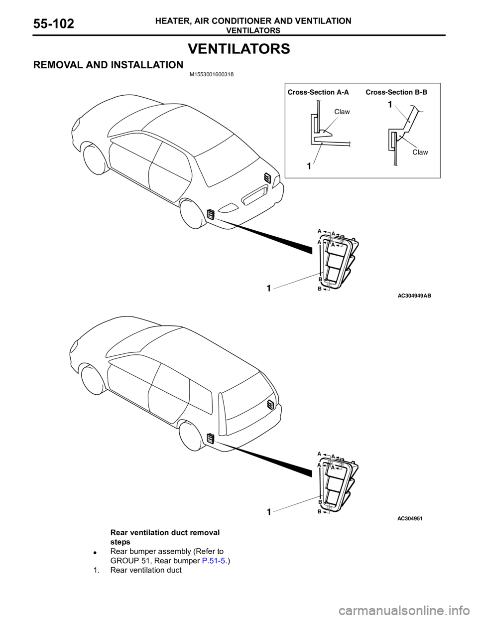
VENTILATORS
REMOVAL AND INSTALLATIONM1553001600318
AC304949
Cross-Section A-A Cross-Section B-B
1
11
Claw
Claw
A
A
B
B
A
A
AB
AC3049511
A
A
B
B
A
A
Rear ventilation duct removal
steps
•Rear bumper assembly (Refer to
GROUP 51, Rear bumper P.51-5.)
1. Rear ventilation duct
Page 587 of 788
70-1
GROUP 70
COMPONENT
LOCATIONS
CONTENTS
ECU . . . . . . . . . . . . . . . . . . . . . . . . . .70-2
RELAY . . . . . . . . . . . . . . . . . . . . . . . .70-5
SENSOR. . . . . . . . . . . . . . . . . . . . . . .70-6
FUSIBLE LINK AND FUSE . . . . . . . .70-10
EARTH CABLE . . . . . . . . . . . . . . . . .70-11SOLENOID VALVE . . . . . . . . . . . . . . .70-11
DIODE . . . . . . . . . . . . . . . . . . . . . . . . .70-13
EARTH . . . . . . . . . . . . . . . . . . . . . . . .70-14
INSPECTION CONNECTOR AND
SPARE CONNECTOR . . . . . . . . . . . .70-18
Page 588 of 788
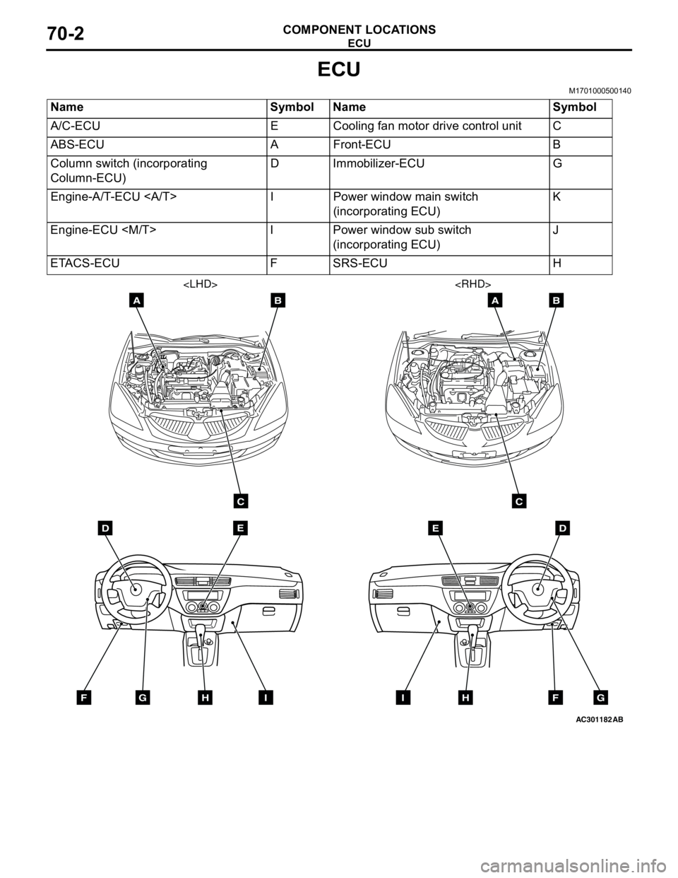
Page 589 of 788
ECU
COMPONENT LOCATIONS70-3
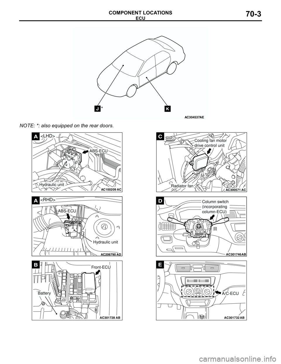
NOTE: *: also equipped on the rear doors.
AC304537
JK*
AE
AC100209AC
A
ABS-ECU
Hydraulic unit
AC206790
A
AD
ABS-ECU
Hydraulic unit
AC301728AB
BFront-ECU
Battery
AC300571
C
ACRadiator fan
Cooling fan motor
drive control unit
AC301746
DColumn switch
(incorporating
column-ECU)
AB
AC301732AB
E
A/C-ECU
Page 590 of 788
Trending: cooling, turn signal, Air con, coolant sensor, Group 80, oil filter, rims
