NISSAN PICK-UP 1998 Repair Manual
Manufacturer: NISSAN, Model Year: 1998, Model line: PICK-UP, Model: NISSAN PICK-UP 1998Pages: 1659, PDF Size: 53.39 MB
Page 1071 of 1659
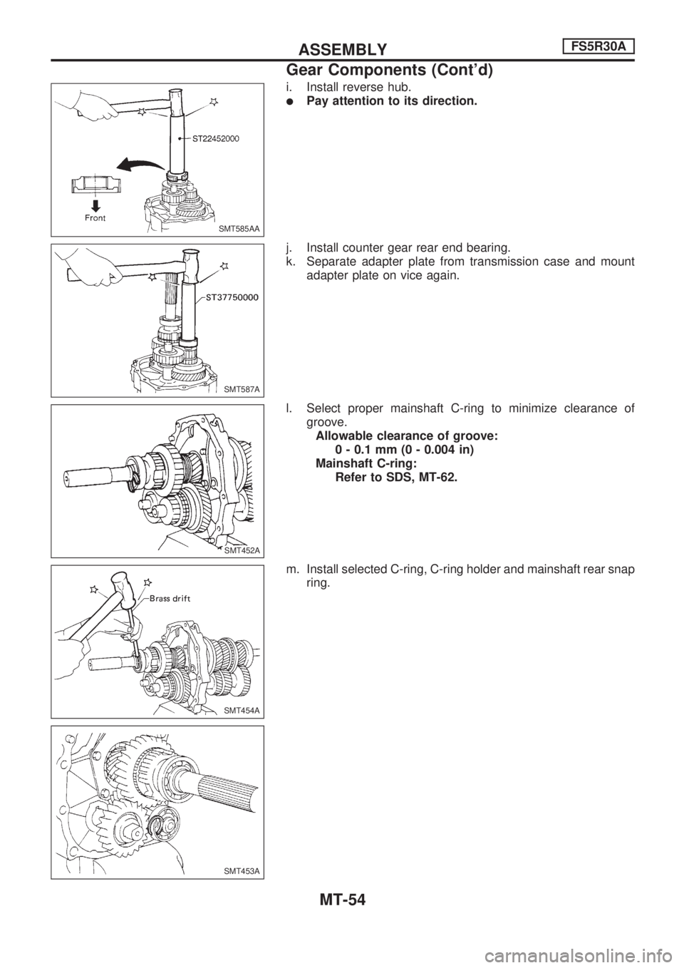
i. Install reverse hub.
lPay attention to its direction.
j. Install counter gear rear end bearing.
k. Separate adapter plate from transmission case and mount
adapter plate on vice again.
l. Select proper mainshaft C-ring to minimize clearance of
groove.
Allowable clearance of groove:
0 - 0.1 mm (0 - 0.004 in)
Mainshaft C-ring:
Refer to SDS, MT-62.
m. Install selected C-ring, C-ring holder and mainshaft rear snap
ring.
SMT585AA
SMT587A
SMT452A.SMT452A
SMT454A
SMT453A
ASSEMBLYFS5R30A
Gear Components (Cont'd)
MT-54
Page 1072 of 1659
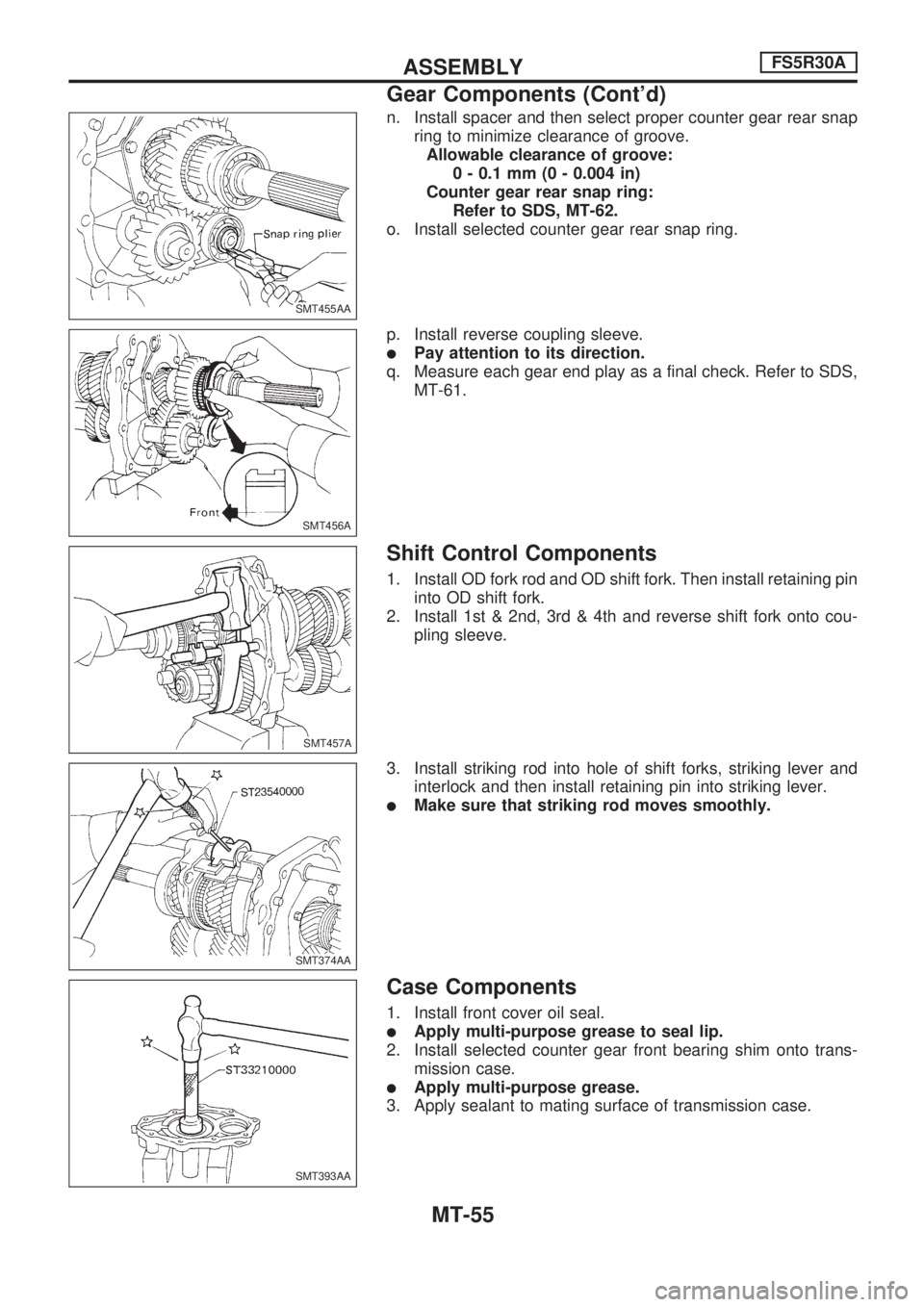
n. Install spacer and then select proper counter gear rear snap
ring to minimize clearance of groove.
Allowable clearance of groove:
0 - 0.1 mm (0 - 0.004 in)
Counter gear rear snap ring:
Refer to SDS, MT-62.
o. Install selected counter gear rear snap ring.
p. Install reverse coupling sleeve.
lPay attention to its direction.
q. Measure each gear end play as a final check. Refer to SDS,
MT-61.
Shift Control Components
1. Install OD fork rod and OD shift fork. Then install retaining pin
into OD shift fork.
2. Install 1st & 2nd, 3rd & 4th and reverse shift fork onto cou-
pling sleeve.
3. Install striking rod into hole of shift forks, striking lever and
interlock and then install retaining pin into striking lever.
lMake sure that striking rod moves smoothly.
Case Components
1. Install front cover oil seal.
lApply multi-purpose grease to seal lip.
2. Install selected counter gear front bearing shim onto trans-
mission case.
lApply multi-purpose grease.
3. Apply sealant to mating surface of transmission case.
SMT455AA.SMT455AA
SMT456A
SMT457A.SMT457A
SMT374AA.SMT374AA
SMT393AA
ASSEMBLYFS5R30A
Gear Components (Cont'd)
MT-55
Page 1073 of 1659
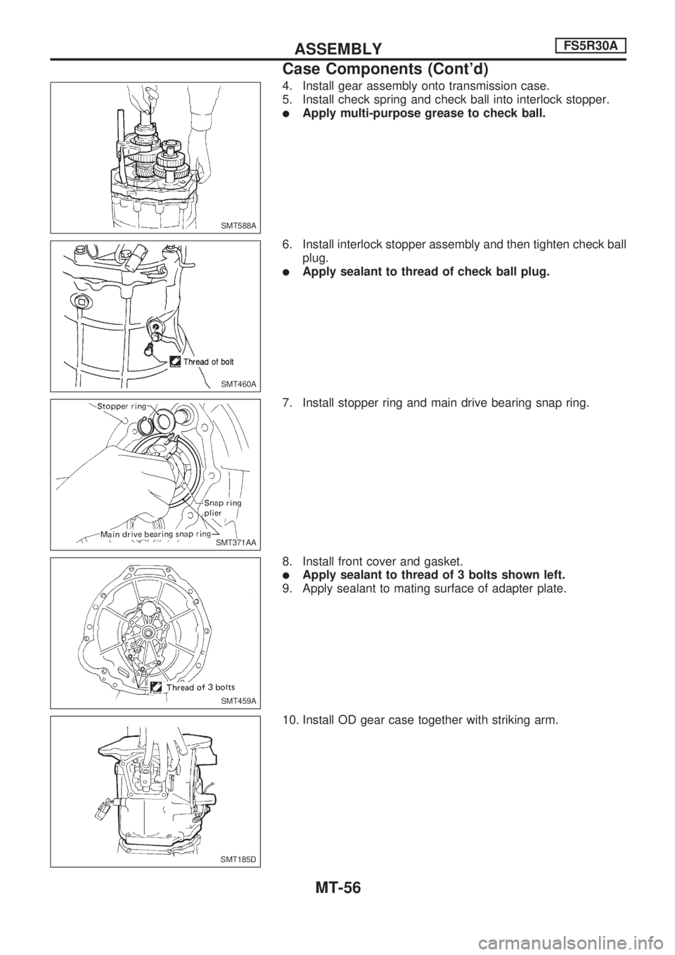
4. Install gear assembly onto transmission case.
5. Install check spring and check ball into interlock stopper.
lApply multi-purpose grease to check ball.
6. Install interlock stopper assembly and then tighten check ball
plug.
lApply sealant to thread of check ball plug.
7. Install stopper ring and main drive bearing snap ring.
8. Install front cover and gasket.
lApply sealant to thread of 3 bolts shown left.
9. Apply sealant to mating surface of adapter plate.
10. Install OD gear case together with striking arm.
SMT588A
SMT460A
SMT371AA
SMT459A
SMT185D
ASSEMBLYFS5R30A
Case Components (Cont'd)
MT-56
Page 1074 of 1659
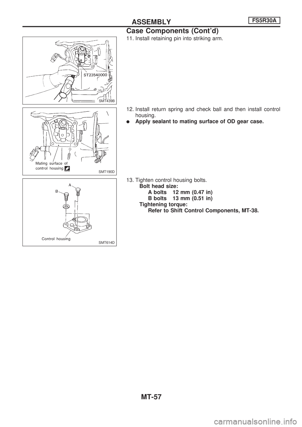
11. Install retaining pin into striking arm.
12. Install return spring and check ball and then install control
housing.
lApply sealant to mating surface of OD gear case.
13. Tighten control housing bolts.
Bolt head size:
A bolts 12 mm (0.47 in)
B bolts 13 mm (0.51 in)
Tightening torque:
Refer to Shift Control Components, MT-38.
SMT439B
SMT190D
SMT614D
ASSEMBLYFS5R30A
Case Components (Cont'd)
MT-57
Page 1075 of 1659
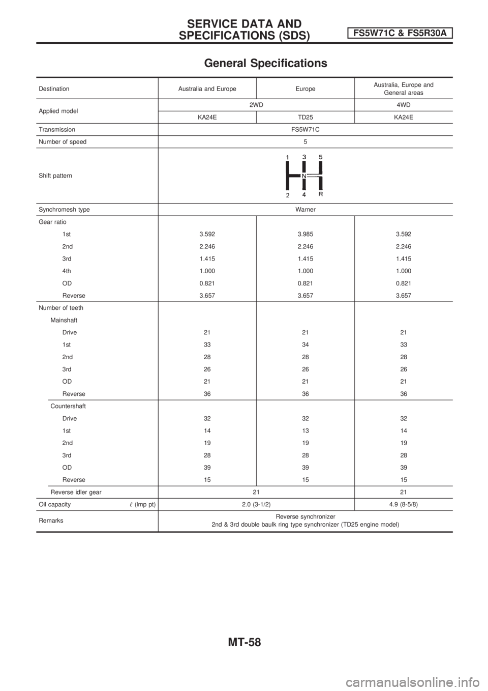
General Specifications
Destination Australia and Europe EuropeAustralia, Europe and
General areas
Applied model2WD 4WD
KA24E TD25 KA24E
TransmissionFS5W71C
Number of speed5
Shift pattern
Synchromesh typeWarner
Gear ratio
1st 3.592 3.985 3.592
2nd 2.246 2.246 2.246
3rd 1.415 1.415 1.415
4th 1.000 1.000 1.000
OD 0.821 0.821 0.821
Reverse 3.657 3.657 3.657
Number of teeth
Mainshaft
Drive 21 21 21
1st 33 34 33
2nd 28 28 28
3rd 26 26 26
OD 21 21 21
Reverse 36 36 36
Countershaft
Drive 32 32 32
1st 14 13 14
2nd 19 19 19
3rd 28 28 28
OD 39 39 39
Reverse 15 15 15
Reverse idler gear 21 21
Oil capacity!(lmp pt) 2.0 (3-1/2) 4.9 (8-5/8)
RemarksReverse synchronizer
2nd & 3rd double baulk ring type synchronizer (TD25 engine model)
SERVICE DATA AND
SPECIFICATIONS (SDS)FS5W71C & FS5R30A
MT-58
Page 1076 of 1659
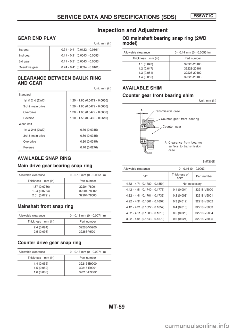
Inspection and Adjustment
GEAR END PLAY
Unit: mm (in)
1st gear 0.31 - 0.41 (0.0122 - 0.0161)
2nd gear 0.11 - 0.21 (0.0043 - 0.0083)
3rd gear 0.11 - 0.21 (0.0043 - 0.0083)
Overdrive gear 0.24 - 0.41 (0.0094 - 0.0161)
CLEARANCE BETWEEN BAULK RING
AND GEAR
Unit: mm (in)
Standard
1st & 2nd (2WD) 1.20 - 1.60 (0.0472 - 0.0630)
3rd & main drive 1.20 - 1.60 (0.0472 - 0.0630)
Overdrive 1.20 - 1.60 (0.0472 - 0.0630)
Reverse 1.10 - 1.55 (0.0433 - 0.0610)
Wear limit
1st & 2nd (2WD) 0.80 (0.0315)
3rd & main drive 0.80 (0.0315)
Overdrive 0.80 (0.0315)
Reverse 0.70 (0.0276)
AVAILABLE SNAP RING
Main drive gear bearing snap ring
Allowable clearance 0 - 0.13 mm (0 - 0.0051 in)
Thickness mm (in) Part number
1.87 (0.0736) 32204-78001
1.94 (0.0764) 32204-78002
2.01 (0.0791) 32204-78003
Mainshaft front snap ring
Allowable clearance 0 - 0.18 mm (0 - 0.0071 in)
Thickness mm (in) Part number
2.4 (0.094) 32263-V5200
2.5 (0.098) 32263-V5201
Counter drive gear snap ring
Allowable clearance 0 - 0.18 mm (0 - 0.0071 in)
Thickness mm (in) Part number
1.4 (0.055) 32215-E9000
1.5 (0.059) 32215-E9001
1.6 (0.063) 32215-E9002
OD mainshaft bearing snap ring (2WD
model)
Allowable clearance 0 - 0.14 mm (0 - 0.0055 in)
Thickness mm (in) Part number
1.1 (0.043) 32228-20100
1.2 (0.047) 32228-20101
1.3 (0.051) 32228-20102
1.4 (0.055) 32228-20103
AVAILABLE SHIM
Counter gear front bearing shim
Unit: mm (in)
SMT205D
Allowable clearance 0 - 0.16 (0 - 0.0063)
``A''Thickness of
shimPart number
4.52 - 4.71 (0.1780 - 0.1854) Not necessary
4.42 - 4.51 (0.1740 - 0.1776) 0.1 (0.004) 32218-V5000
4.32 - 4.41 (0.1701 - 0.1736) 0.2 (0.008) 32218-V5001
4.22 - 4.31 (0.1661 - 0.1697) 0.3 (0.012) 32218-V5002
4.12 - 4.21 (0.1622 - 0.1657) 0.4 (0.016) 32218-V5003
4.02 - 4.11 (0.1583 - 0.1618) 0.5 (0.020) 32218-V5004
3.92 - 4.01 (0.1543 - 0.1579) 0.6 (0.024) 32218-V5005
SERVICE DATA AND SPECIFICATIONS (SDS)FS5W71C
MT-59
Page 1077 of 1659
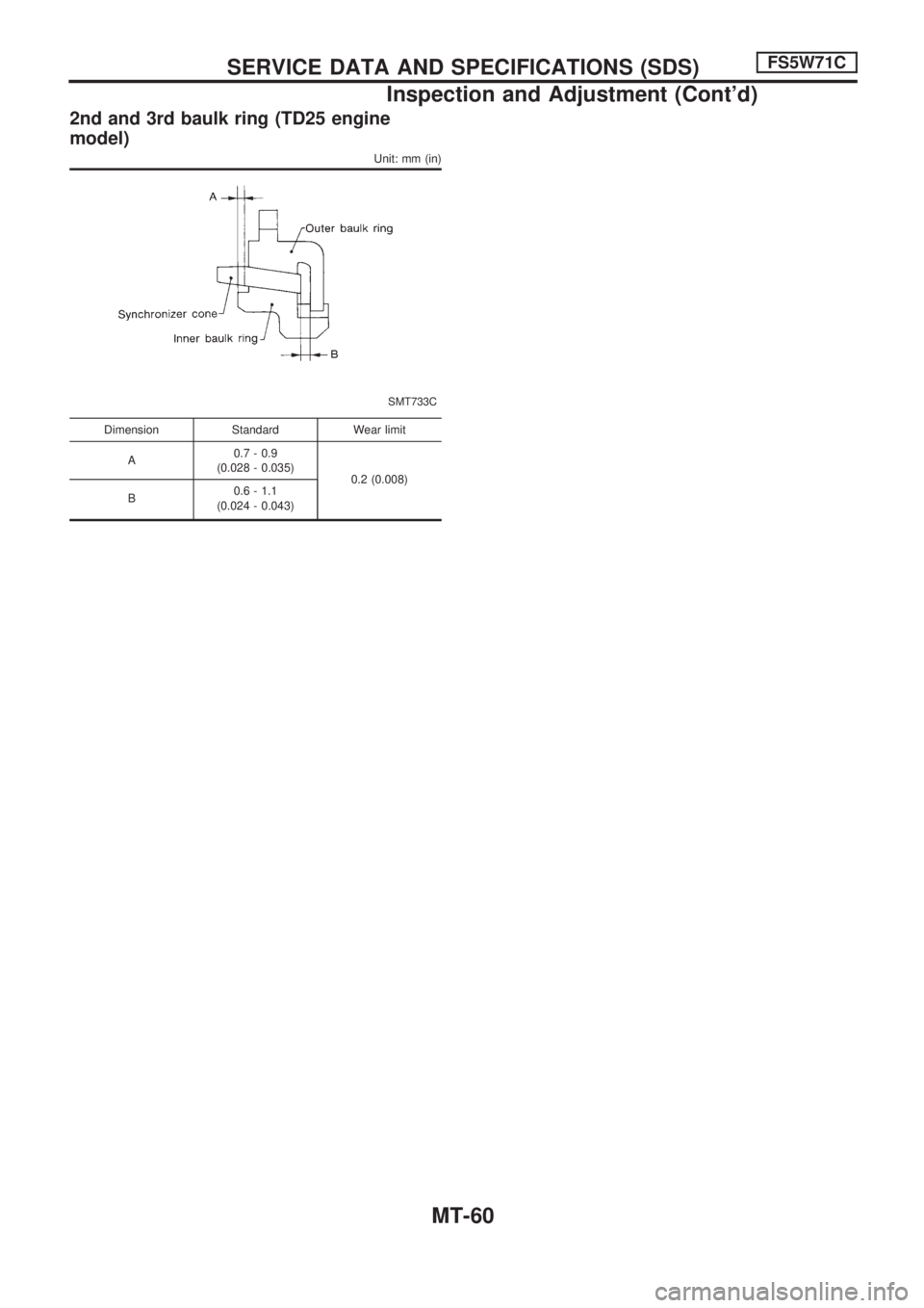
2nd and 3rd baulk ring (TD25 engine
model)
Unit: mm (in)
SMT733C
Dimension Standard Wear limit
A0.7 - 0.9
(0.028 - 0.035)
0.2 (0.008)
B0.6 - 1.1
(0.024 - 0.043)
SERVICE DATA AND SPECIFICATIONS (SDS)FS5W71C
Inspection and Adjustment (Cont'd)
MT-60
Page 1078 of 1659
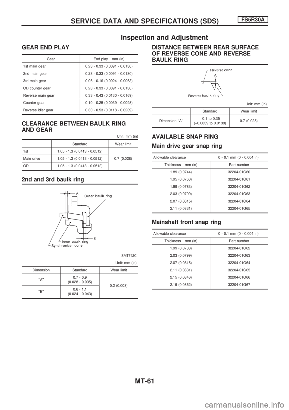
Inspection and Adjustment
GEAR END PLAY
Gear End play mm (in)
1st main gear 0.23 - 0.33 (0.0091 - 0.0130)
2nd main gear 0.23 - 0.33 (0.0091 - 0.0130)
3rd main gear 0.06 - 0.16 (0.0024 - 0.0063)
OD counter gear 0.23 - 0.33 (0.0091 - 0.0130)
Reverse main gear 0.33 - 0.43 (0.0130 - 0.0169)
Counter gear 0.10 - 0.25 (0.0039 - 0.0098)
Reverse idler gear 0.30 - 0.53 (0.0118 - 0.0209)
CLEARANCE BETWEEN BAULK RING
AND GEAR
Unit: mm (in)
Standard Wear limit
1st 1.05 - 1.3 (0.0413 - 0.0512)
0.7 (0.028) Main drive 1.05 - 1.3 (0.0413 - 0.0512)
OD 1.05 - 1.3 (0.0413 - 0.0512)
2nd and 3rd baulk ring
SMT742C
Unit: mm (in)
Dimension Standard Wear limit
``A''0.7 - 0.9
(0.028 - 0.035)
0.2 (0.008)
``B''0.6 - 1.1
(0.024 - 0.043)
DISTANCE BETWEEN REAR SURFACE
OF REVERSE CONE AND REVERSE
BAULK RING
Unit: mm (in)
Standard Wear limit
Dimension ``A''þ0.1 to 0.35
(þ0.0039 to 0.0138)0.7 (0.028)
AVAILABLE SNAP RING
Main drive gear snap ring
Allowable clearance 0 - 0.1 mm (0 - 0.004 in)
Thickness mm (in) Part number
1.89 (0.0744) 32204-01G60
1.95 (0.0768) 32204-01G61
1.99 (0.0783) 32204-01G62
2.03 (0.0799) 32204-01G63
2.07 (0.0815) 32204-01G64
2.11 (0.0831) 32204-01G65
Mainshaft front snap ring
Allowable clearance 0 - 0.1 mm (0 - 0.004 in)
Thickness mm (in) Part number
1.99 (0.0783) 32204-01G62
2.03 (0.0799) 32204-01G63
2.07 (0.0815) 32204-01G64
2.11 (0.0831) 32204-01G65
2.15 (0.0846) 32204-01G66
2.19 (0.0862) 32204-01G67
SERVICE DATA AND SPECIFICATIONS (SDS)FS5R30A
MT-61
Page 1079 of 1659
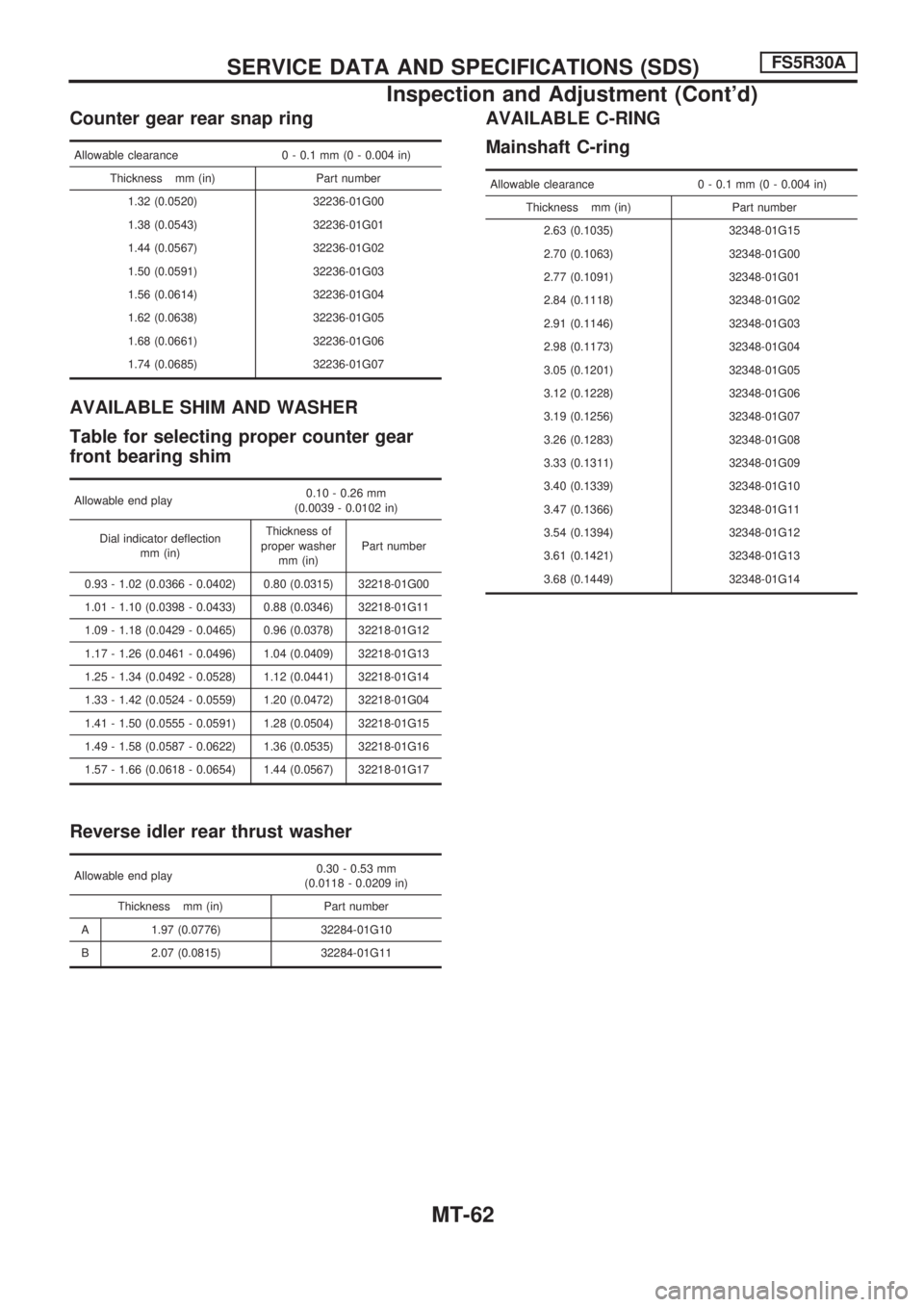
Counter gear rear snap ring
Allowable clearance 0 - 0.1 mm (0 - 0.004 in)
Thickness mm (in) Part number
1.32 (0.0520) 32236-01G00
1.38 (0.0543) 32236-01G01
1.44 (0.0567) 32236-01G02
1.50 (0.0591) 32236-01G03
1.56 (0.0614) 32236-01G04
1.62 (0.0638) 32236-01G05
1.68 (0.0661) 32236-01G06
1.74 (0.0685) 32236-01G07
AVAILABLE SHIM AND WASHER
Table for selecting proper counter gear
front bearing shim
Allowable end play0.10 - 0.26 mm
(0.0039 - 0.0102 in)
Dial indicator deflection
mm (in)Thickness of
proper washer
mm (in)Part number
0.93 - 1.02 (0.0366 - 0.0402) 0.80 (0.0315) 32218-01G00
1.01 - 1.10 (0.0398 - 0.0433) 0.88 (0.0346) 32218-01G11
1.09 - 1.18 (0.0429 - 0.0465) 0.96 (0.0378) 32218-01G12
1.17 - 1.26 (0.0461 - 0.0496) 1.04 (0.0409) 32218-01G13
1.25 - 1.34 (0.0492 - 0.0528) 1.12 (0.0441) 32218-01G14
1.33 - 1.42 (0.0524 - 0.0559) 1.20 (0.0472) 32218-01G04
1.41 - 1.50 (0.0555 - 0.0591) 1.28 (0.0504) 32218-01G15
1.49 - 1.58 (0.0587 - 0.0622) 1.36 (0.0535) 32218-01G16
1.57 - 1.66 (0.0618 - 0.0654) 1.44 (0.0567) 32218-01G17
Reverse idler rear thrust washer
Allowable end play0.30 - 0.53 mm
(0.0118 - 0.0209 in)
Thickness mm (in) Part number
A 1.97 (0.0776) 32284-01G10
B 2.07 (0.0815) 32284-01G11
AVAILABLE C-RING
Mainshaft C-ring
Allowable clearance 0 - 0.1 mm (0 - 0.004 in)
Thickness mm (in) Part number
2.63 (0.1035) 32348-01G15
2.70 (0.1063) 32348-01G00
2.77 (0.1091) 32348-01G01
2.84 (0.1118) 32348-01G02
2.91 (0.1146) 32348-01G03
2.98 (0.1173) 32348-01G04
3.05 (0.1201) 32348-01G05
3.12 (0.1228) 32348-01G06
3.19 (0.1256) 32348-01G07
3.26 (0.1283) 32348-01G08
3.33 (0.1311) 32348-01G09
3.40 (0.1339) 32348-01G10
3.47 (0.1366) 32348-01G11
3.54 (0.1394) 32348-01G12
3.61 (0.1421) 32348-01G13
3.68 (0.1449) 32348-01G14
SERVICE DATA AND SPECIFICATIONS (SDS)FS5R30A
Inspection and Adjustment (Cont'd)
MT-62
Page 1080 of 1659
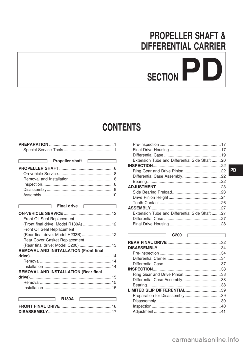
PROPELLER SHAFT &
DIFFERENTIAL CARRIER
SECTION
PD
CONTENTS
PREPARATION......................................................... 1
Special Service Tools ............................................ 1
Propeller shaft
PROPELLER SHAFT................................................ 6
On-vehicle Service ................................................. 8
Removal and Installation ....................................... 8
Inspection ............................................................... 8
Disassembly ........................................................... 9
Assembly.............................................................. 10
Final drive
ON-VEHICLE SERVICE.......................................... 12
Front Oil Seal Replacement
(Front final drive: Model R180A) ......................... 12
Front Oil Seal Replacement
(Rear final drive: Model H233B) .......................... 12
Rear Cover Gasket Replacement
(Rear final drive: Model C200) ............................ 13
REMOVAL AND INSTALLATION (Front final
drive)........................................................................ 14
Removal ............................................................... 14
Installation ............................................................ 14
REMOVAL AND INSTALLATION (Rear final
drive)........................................................................ 15
Removal ............................................................... 15
Installation ............................................................ 15
R180A
FRONT FINAL DRIVE............................................. 16
DISASSEMBLY........................................................ 17Pre-inspection ...................................................... 17
Final Drive Housing ............................................. 17
Differential Case .................................................. 19
Extension Tube and Differential Side Shaft ........ 20
INSPECTION............................................................ 22
Ring Gear and Drive Pinion................................. 22
Differential Case Assembly.................................. 22
Bearing ................................................................. 22
ADJUSTMENT......................................................... 23
Side Bearing Preload ........................................... 23
Drive Pinion Height .............................................. 24
Tooth Contact ...................................................... 26
ASSEMBLY.............................................................. 27
Extension Tube and Differential Side Shaft ........ 27
Differential Case .................................................. 27
Final Drive Housing ............................................. 28
C200
REAR FINAL DRIVE............................................... 32
DISASSEMBLY........................................................ 34
Pre-inspection ...................................................... 34
Differential Carrier ................................................ 34
Differential Case .................................................. 37
INSPECTION............................................................ 38
Ring Gear and Drive Pinion................................. 38
Differential Case Assembly.................................. 38
Bearing ................................................................. 38
LIMITED SLIP DIFFERENTIAL............................... 39
Preparation for Disassembly................................ 39
Disassembly ......................................................... 39
Inspection ............................................................. 40
Adjustment ........................................................... 41
PD