NISSAN PICK-UP 1998 Repair Manual
Manufacturer: NISSAN, Model Year: 1998, Model line: PICK-UP, Model: NISSAN PICK-UP 1998Pages: 1659, PDF Size: 53.39 MB
Page 1081 of 1659
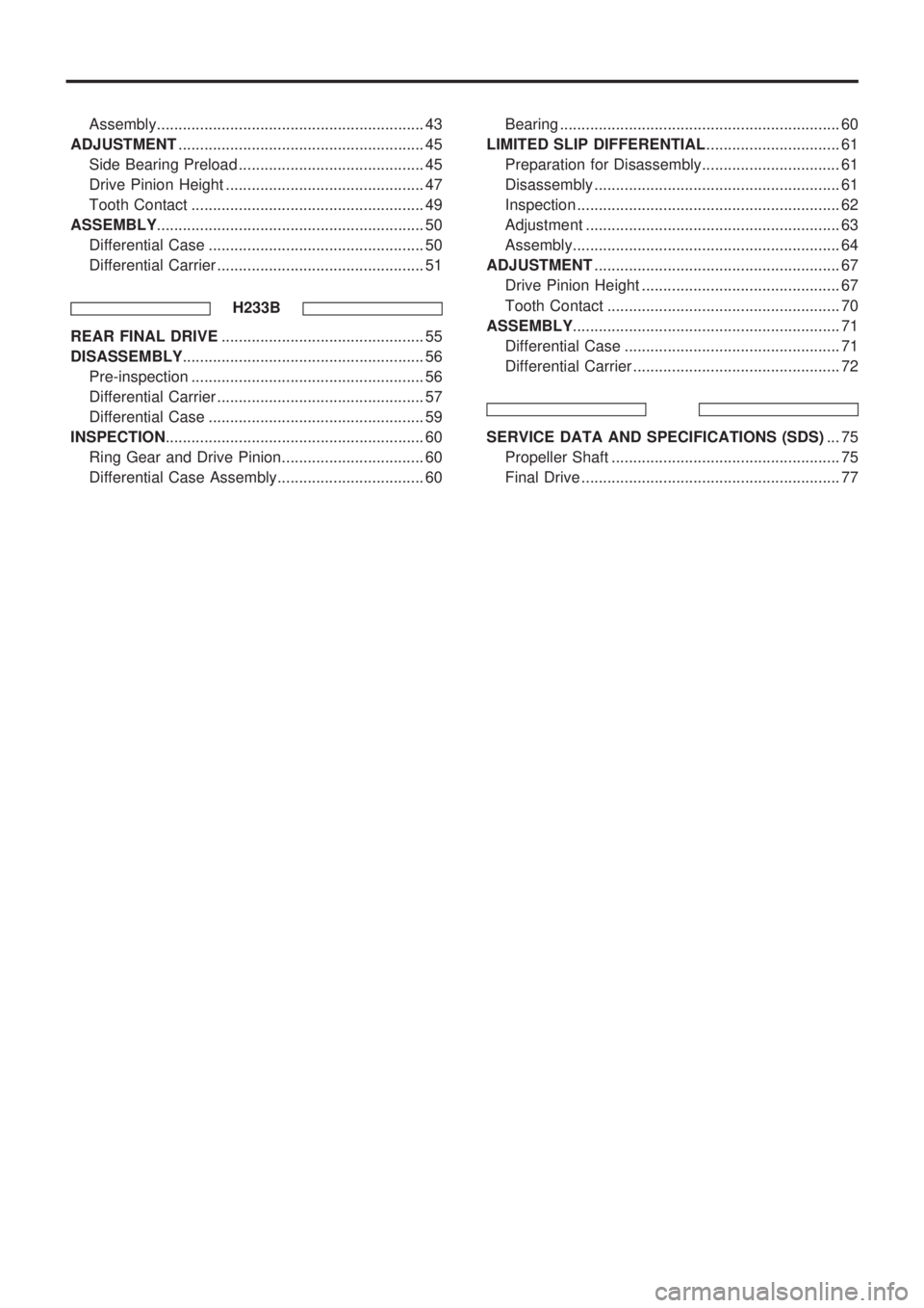
Assembly.............................................................. 43
ADJUSTMENT......................................................... 45
Side Bearing Preload ........................................... 45
Drive Pinion Height .............................................. 47
Tooth Contact ...................................................... 49
ASSEMBLY.............................................................. 50
Differential Case .................................................. 50
Differential Carrier ................................................ 51
H233B
REAR FINAL DRIVE............................................... 55
DISASSEMBLY........................................................ 56
Pre-inspection ...................................................... 56
Differential Carrier ................................................ 57
Differential Case .................................................. 59
INSPECTION............................................................ 60
Ring Gear and Drive Pinion................................. 60
Differential Case Assembly.................................. 60Bearing ................................................................. 60
LIMITED SLIP DIFFERENTIAL............................... 61
Preparation for Disassembly................................ 61
Disassembly ......................................................... 61
Inspection ............................................................. 62
Adjustment ........................................................... 63
Assembly.............................................................. 64
ADJUSTMENT......................................................... 67
Drive Pinion Height .............................................. 67
Tooth Contact ...................................................... 70
ASSEMBLY.............................................................. 71
Differential Case .................................................. 71
Differential Carrier ................................................ 72
SERVICE DATA AND SPECIFICATIONS (SDS)... 75
Propeller Shaft ..................................................... 75
Final Drive ............................................................ 77
Page 1082 of 1659
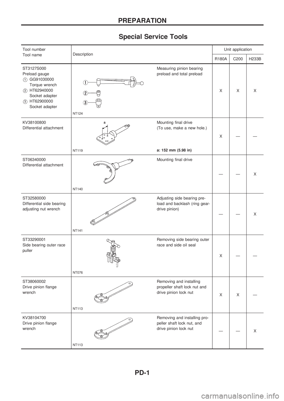
Special Service Tools
Tool number
Tool nameDescriptionUnit application
R180A C200 H233B
ST3127S000
Preload gauge
V1GG91030000
Torque wrench
V2HT62940000
Socket adapter
V3HT62900000
Socket adapter
NT124
Measuring pinion bearing
preload and total preload
XXX
KV38100800
Differential attachment
NT119
Mounting final drive
(To use, make a new hole.)
XÐÐ
a: 152 mm (5.98 in)
ST06340000
Differential attachment
NT140
Mounting final drive
ÐÐ X
ST32580000
Differential side bearing
adjusting nut wrench
NT141
Adjusting side bearing pre-
load and backlash (ring gear-
drive pinion)
ÐÐ X
ST33290001
Side bearing outer race
puller
NT076
Removing side bearing outer
race and side oil seal
XÐÐ
ST38060002
Drive pinion flange
wrench
NT113
Removing and installing
propeller shaft lock nut and
drive pinion lock nut
XXÐ
KV38104700
Drive pinion flange
wrench
NT113
Removing and installing pro-
peller shaft lock nut, and
drive pinion lock nut
ÐÐ X
PREPARATION
PD-1
Page 1083 of 1659
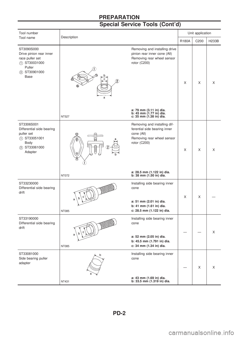
Tool number
Tool nameDescriptionUnit application
R180A C200 H233B
ST3090S000
Drive pinion rear inner
race puller set
V1ST30031000
Puller
V2ST30901000
Base
NT527
Removing and installing drive
pinion rear inner cone (All)
Removing rear wheel sensor
rotor (C200)
XXX
a: 79 mm (3.11 in) dia.
b: 45 mm (1.77 in) dia.
c: 35 mm (1.38 in) dia.
ST3306S001
Differential side bearing
puller set
V1ST33051001
Body
V2ST33061000
Adapter
NT072
Removing and installing dif-
ferential side bearing inner
cone (All)
Removing rear wheel sensor
rotor (C200)
XXX
a: 28.5 mm (1.122 in) dia.
b: 38 mm (1.50 in) dia.
ST33230000
Differential side bearing
drift
NT085
Installing side bearing inner
cone
XXÐ
a: 51 mm (2.01 in) dia.
b: 41 mm (1.61 in) dia.
c: 28.5 mm (1.122 in) dia.
ST33190000
Differential side bearing
drift
NT085
Installing side bearing inner
cone
ÐÐ X
a: 52 mm (2.05 in) dia.
b: 45.5 mm (1.791 in) dia.
c: 34 mm (1.34 in) dia.
ST33081000
Side bearing puller
adapter
NT431
Installing side bearing inner
cone
ÐX X
a: 43 mm (1.69 in) dia.
b: 33.5 mm (1.319 in) dia.
PREPARATION
Special Service Tools (Cont'd)
PD-2
Page 1084 of 1659
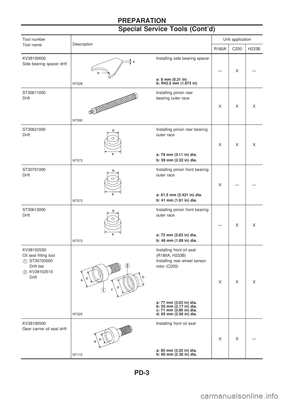
Tool number
Tool nameDescriptionUnit application
R180A C200 H233B
KV38100600
Side bearing spacer drift
NT528
Installing side bearing spacer
ÐXÐ
a: 8 mm (0.31 in)
b: R42.5 mm (1.673 in)
ST30611000
Drift
NT090
Installing pinion rear
bearing outer race
XXX
ST30621000
Drift
NT073
Installing pinion rear bearing
outer race
XXX
a: 79 mm (3.11 in) dia.
b: 59 mm (2.32 in) dia.
ST30701000
Drift
NT073
Installing pinion front bearing
outer race
XÐÐ
a: 61.5 mm (2.421 in) dia.
b: 41 mm (1.61 in) dia.
ST30613000
Drift
NT073
Installing pinion front bearing
outer race
ÐX X
a: 72 mm (2.83 in) dia.
b: 48 mm (1.89 in) dia.
KV381025S0
Oil seal fitting tool
V1ST30720000
Drift bar
V2KV38102510
Drift
NT525
Installing front oil seal
(R180A, H233B)
Installing rear wheel sensor
rotor (C200)
XXX
a: 77 mm (3.03 in) dia.
b: 55 mm (2.17 in) dia.
c: 71 mm (2.80 in) dia.
d: 65 mm (2.56 in) dia.
KV38100500
Gear carrier oil seal drift
NT115
Installing front oil seal
XXÐ
a: 85 mm (3.35 in) dia.
b: 60 mm (2.36 in) dia.
PREPARATION
Special Service Tools (Cont'd)
PD-3
Page 1085 of 1659
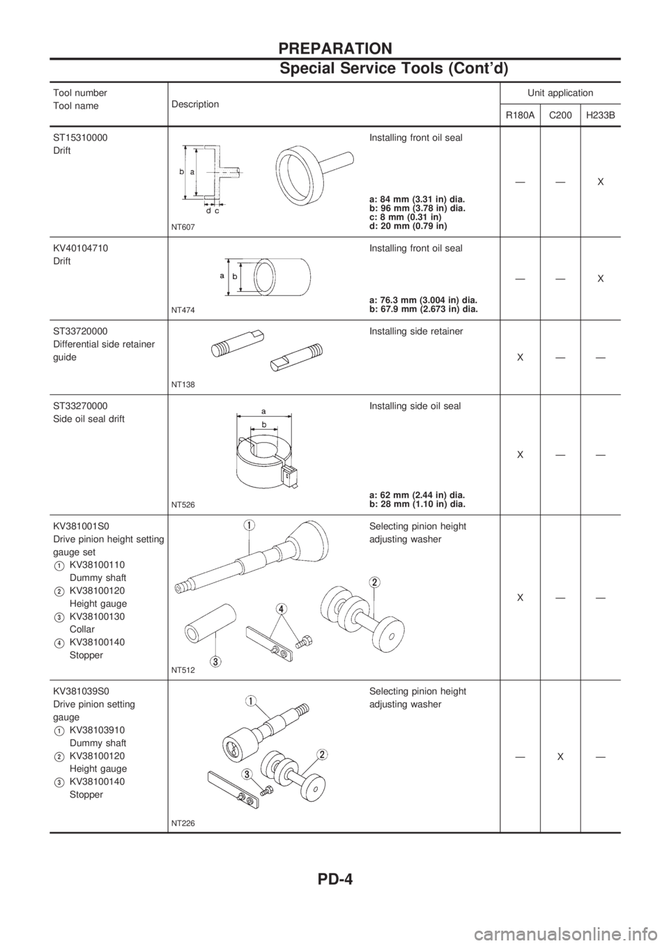
Tool number
Tool nameDescriptionUnit application
R180A C200 H233B
ST15310000
Drift
NT607
Installing front oil seal
ÐÐ X
a: 84 mm (3.31 in) dia.
b: 96 mm (3.78 in) dia.
c: 8 mm (0.31 in)
d: 20 mm (0.79 in)
KV40104710
Drift
NT474
Installing front oil seal
ÐÐ X
a: 76.3 mm (3.004 in) dia.
b: 67.9 mm (2.673 in) dia.
ST33720000
Differential side retainer
guide
NT138
Installing side retainer
XÐÐ
ST33270000
Side oil seal drift
NT526
Installing side oil seal
XÐÐ
a: 62 mm (2.44 in) dia.
b: 28 mm (1.10 in) dia.
KV381001S0
Drive pinion height setting
gauge set
V1KV38100110
Dummy shaft
V2KV38100120
Height gauge
V3KV38100130
Collar
V4KV38100140
Stopper
NT512
Selecting pinion height
adjusting washer
XÐÐ
KV381039S0
Drive pinion setting
gauge
V1KV38103910
Dummy shaft
V2KV38100120
Height gauge
V3KV38100140
Stopper
NT226
Selecting pinion height
adjusting washer
ÐXÐ
PREPARATION
Special Service Tools (Cont'd)
PD-4
Page 1086 of 1659
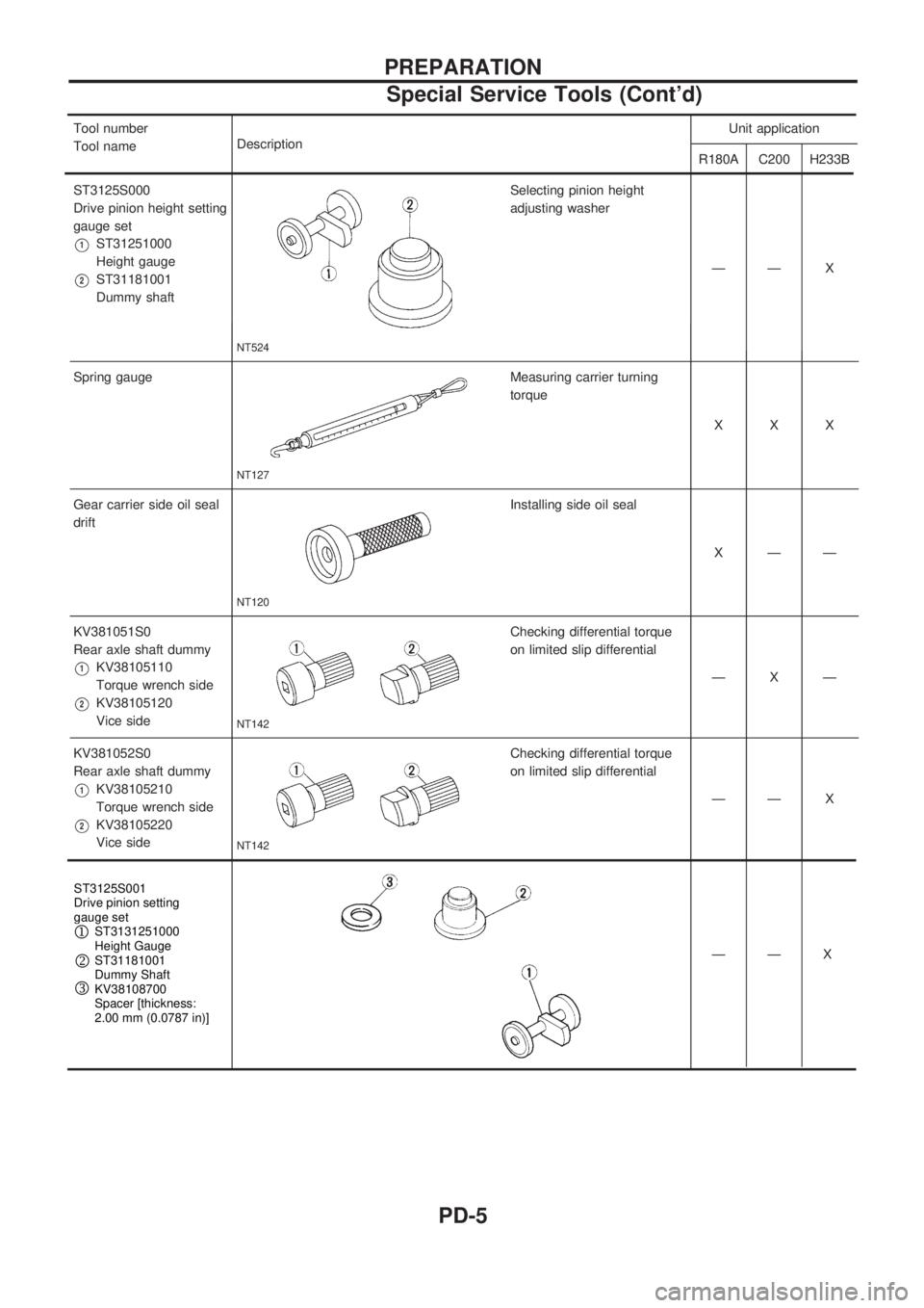
Tool number
Tool nameDescription Unit application
R180A C200 H233B
ST3125S000
Drive pinion height setting
gauge set
V1ST31251000
Height gauge
V2ST31181001
Dummy shaft
NT524
Selecting pinion height
adjusting washer
ÐÐ X
Spring gauge
NT127
Measuring carrier turning
torque XXX
Gear carrier side oil seal
drift
NT120
Installing side oil seal XÐÐ
KV381051S0
Rear axle shaft dummy
V1KV38105110
Torque wrench side
V2KV38105120
Vice side
NT142
Checking differential torque
on limited slip differential ÐXÐ
KV381052S0
Rearaxleshaftdummy
V1KV38105210
Torque wrench side
V2KV38105220
Vice side
NT142
Checking differential torque
on limited slip differential ÐÐX
——X
—X
PREPARATION
Special Service Tools (Cont'd)
PD-5
Page 1087 of 1659
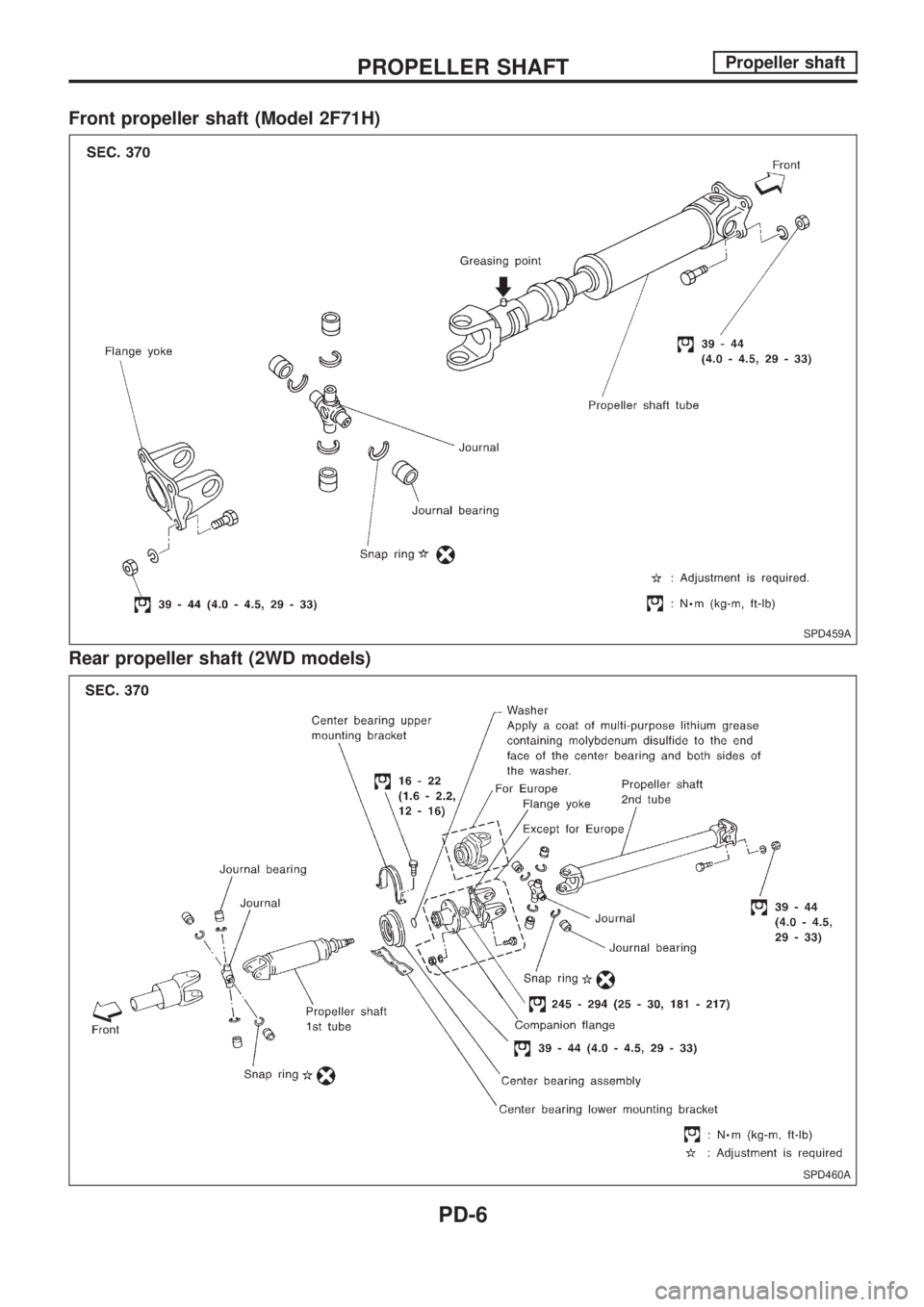
Front propeller shaft (Model 2F71H)
Rear propeller shaft (2WD models)
SPD459A
SPD460A
PROPELLER SHAFTPropeller shaft
PD-6
Page 1088 of 1659
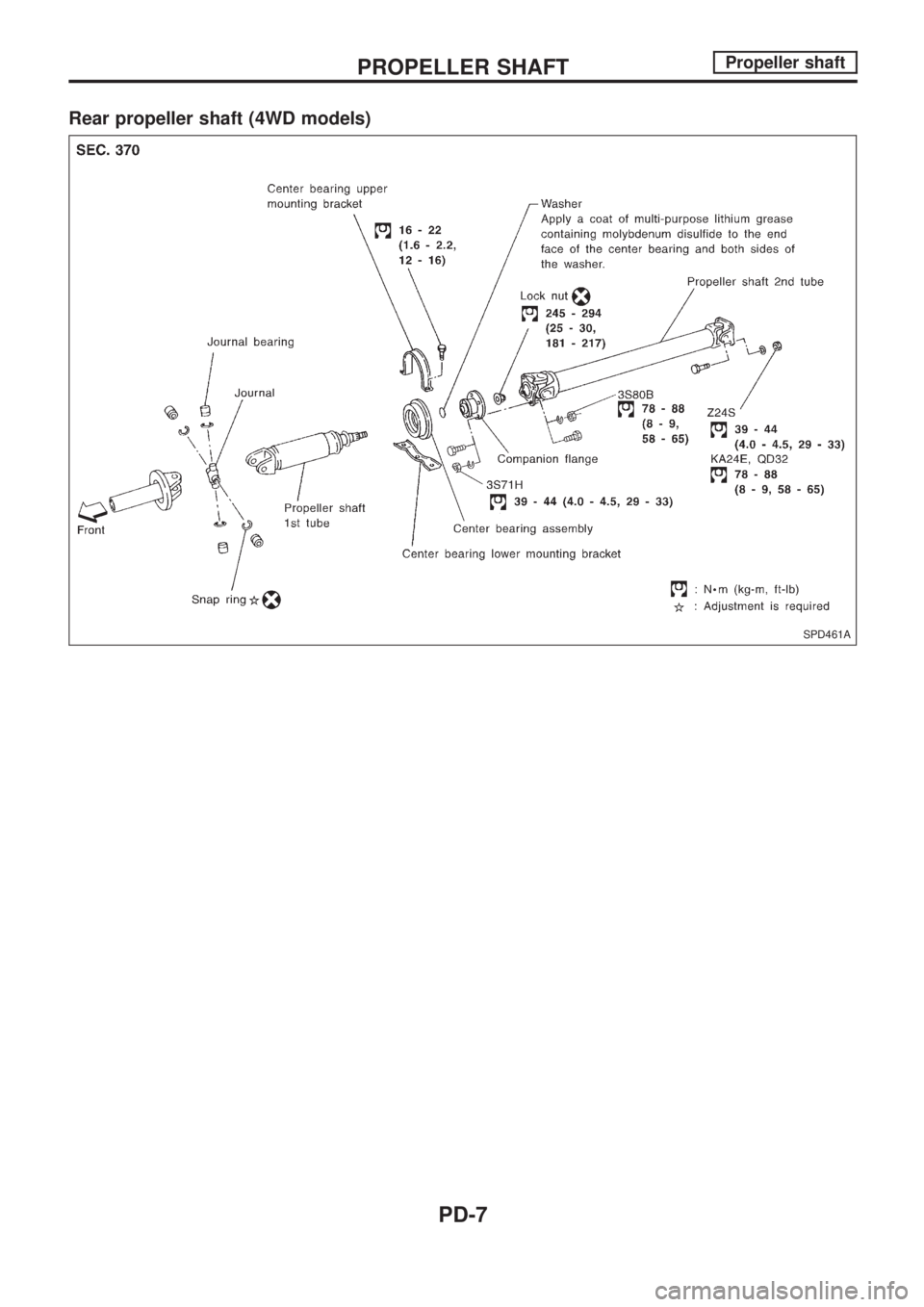
Rear propeller shaft (4WD models)
SPD461A
PROPELLER SHAFTPropeller shaft
PD-7
Page 1089 of 1659
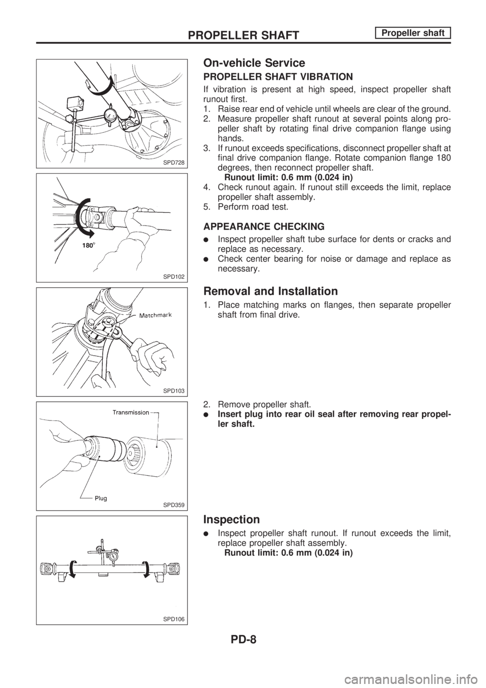
On-vehicle Service
PROPELLER SHAFT VIBRATION
If vibration is present at high speed, inspect propeller shaft
runout first.
1. Raise rear end of vehicle until wheels are clear of the ground.
2. Measure propeller shaft runout at several points along pro-
peller shaft by rotating final drive companion flange using
hands.
3. If runout exceeds specifications, disconnect propeller shaft at
final drive companion flange. Rotate companion flange 180
degrees, then reconnect propeller shaft.
Runout limit: 0.6 mm (0.024 in)
4. Check runout again. If runout still exceeds the limit, replace
propeller shaft assembly.
5. Perform road test.
APPEARANCE CHECKING
lInspect propeller shaft tube surface for dents or cracks and
replace as necessary.
lCheck center bearing for noise or damage and replace as
necessary.
Removal and Installation
1. Place matching marks on flanges, then separate propeller
shaft from final drive.
2. Remove propeller shaft.
lInsert plug into rear oil seal after removing rear propel-
ler shaft.
Inspection
lInspect propeller shaft runout. If runout exceeds the limit,
replace propeller shaft assembly.
Runout limit: 0.6 mm (0.024 in)
SPD728
SPD102
SPD103
SPD359
SPD106
PROPELLER SHAFTPropeller shaft
PD-8
Page 1090 of 1659
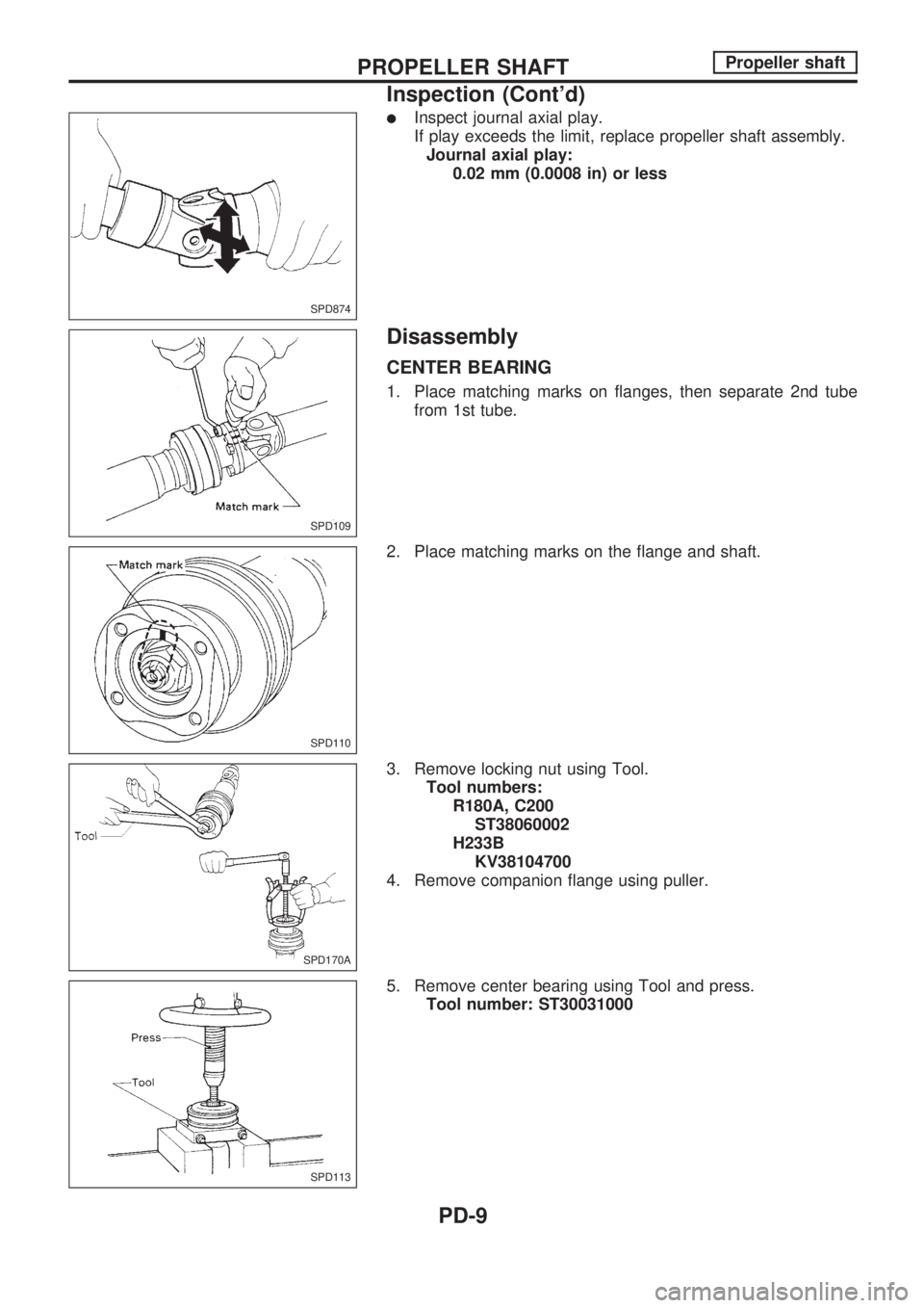
lInspect journal axial play.
If play exceeds the limit, replace propeller shaft assembly.
Journal axial play:
0.02 mm (0.0008 in) or less
Disassembly
CENTER BEARING
1. Place matching marks on flanges, then separate 2nd tube
from 1st tube.
2. Place matching marks on the flange and shaft.
3. Remove locking nut using Tool.
Tool numbers:
R180A, C200
ST38060002
H233B
KV38104700
4. Remove companion flange using puller.
5. Remove center bearing using Tool and press.
Tool number: ST30031000
SPD874
SPD109
SPD110
SPD170A
SPD113
PROPELLER SHAFTPropeller shaft
Inspection (Cont'd)
PD-9