NISSAN PICK-UP 1998 Repair Manual
PICK-UP 1998
NISSAN
NISSAN
https://www.carmanualsonline.info/img/5/57374/w960_57374-0.png
NISSAN PICK-UP 1998 Repair Manual
Trending: coolant temperature, height, power steering fluid, audio, charging, sensor, horn harness
Page 1061 of 1659
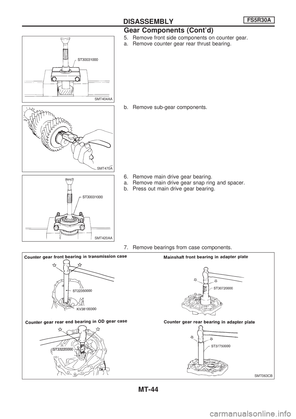
5. Remove front side components on counter gear.
a. Remove counter gear rear thrust bearing.
b. Remove sub-gear components.
6. Remove main drive gear bearing.
a. Remove main drive gear snap ring and spacer.
b. Press out main drive gear bearing.
7. Remove bearings from case components.
SMT404AA
SMT470A.SMT470A
SMT420AA
SMT063CB
DISASSEMBLYFS5R30A
Gear Components (Cont'd)
MT-44
Page 1062 of 1659
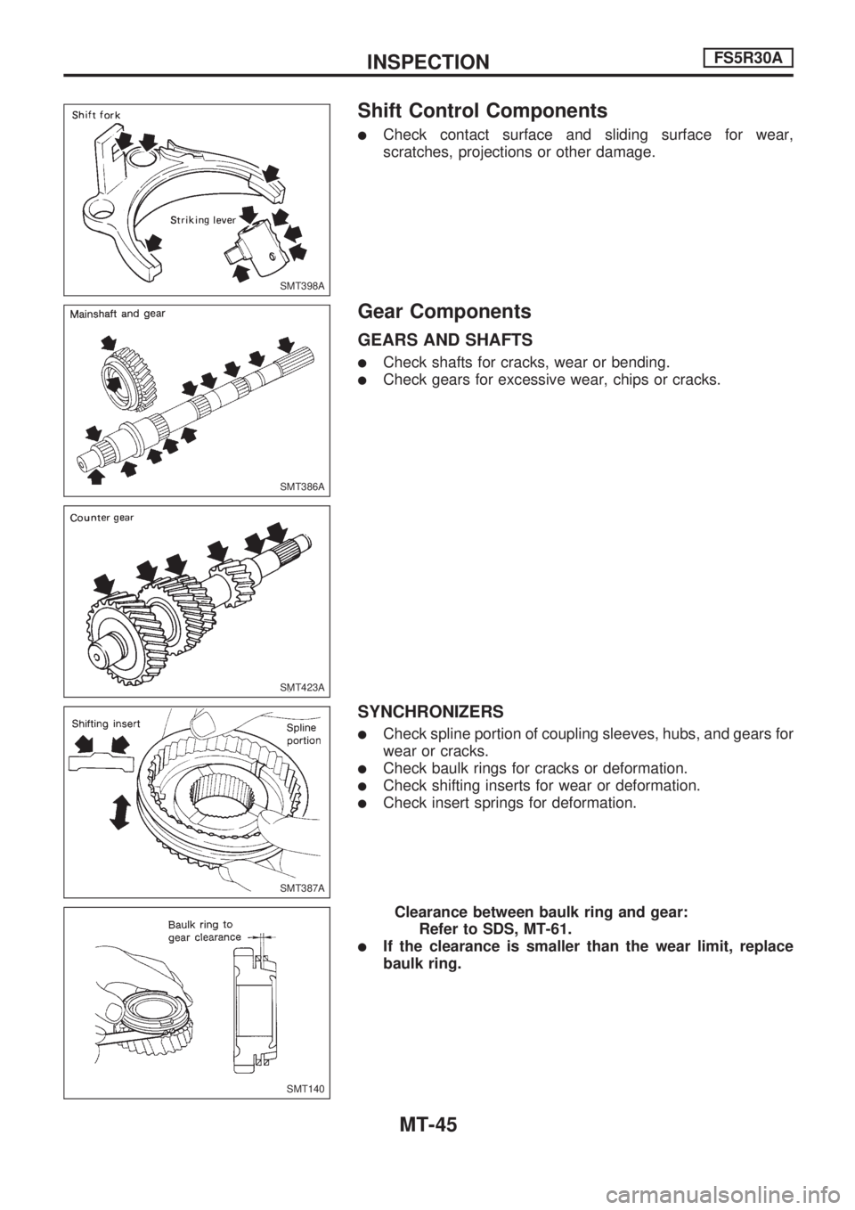
Shift Control Components
lCheck contact surface and sliding surface for wear,
scratches, projections or other damage.
Gear Components
GEARS AND SHAFTS
lCheck shafts for cracks, wear or bending.
lCheck gears for excessive wear, chips or cracks.
SYNCHRONIZERS
lCheck spline portion of coupling sleeves, hubs, and gears for
wear or cracks.
lCheck baulk rings for cracks or deformation.
lCheck shifting inserts for wear or deformation.
lCheck insert springs for deformation.
Clearance between baulk ring and gear:
Refer to SDS, MT-61.
lIf the clearance is smaller than the wear limit, replace
baulk ring.
SMT398A
SMT386A
SMT423A
SMT387A
SMT140
INSPECTIONFS5R30A
MT-45
Page 1063 of 1659
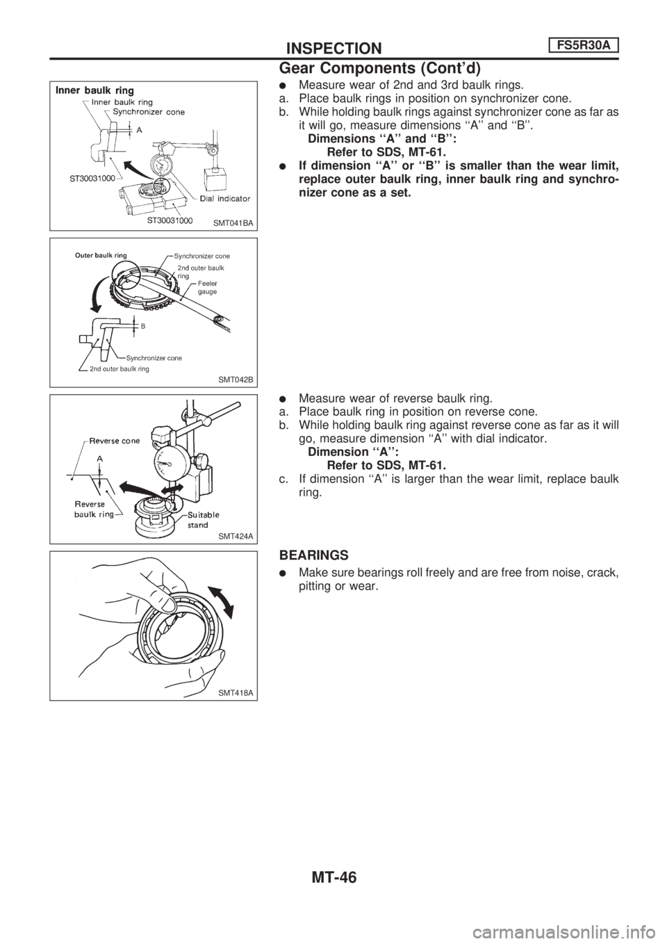
lMeasure wear of 2nd and 3rd baulk rings.
a. Place baulk rings in position on synchronizer cone.
b. While holding baulk rings against synchronizer cone as far as
it will go, measure dimensions ``A'' and ``B''.
Dimensions ``A'' and ``B'':
Refer to SDS, MT-61.
lIf dimension ``A'' or ``B'' is smaller than the wear limit,
replace outer baulk ring, inner baulk ring and synchro-
nizer cone as a set.
lMeasure wear of reverse baulk ring.
a. Place baulk ring in position on reverse cone.
b. While holding baulk ring against reverse cone as far as it will
go, measure dimension ``A'' with dial indicator.
Dimension ``A'':
Refer to SDS, MT-61.
c. If dimension ``A'' is larger than the wear limit, replace baulk
ring.
BEARINGS
lMake sure bearings roll freely and are free from noise, crack,
pitting or wear.
SMT041BA
SMT042B
SMT424A
SMT418A
INSPECTIONFS5R30A
Gear Components (Cont'd)
MT-46
Page 1064 of 1659
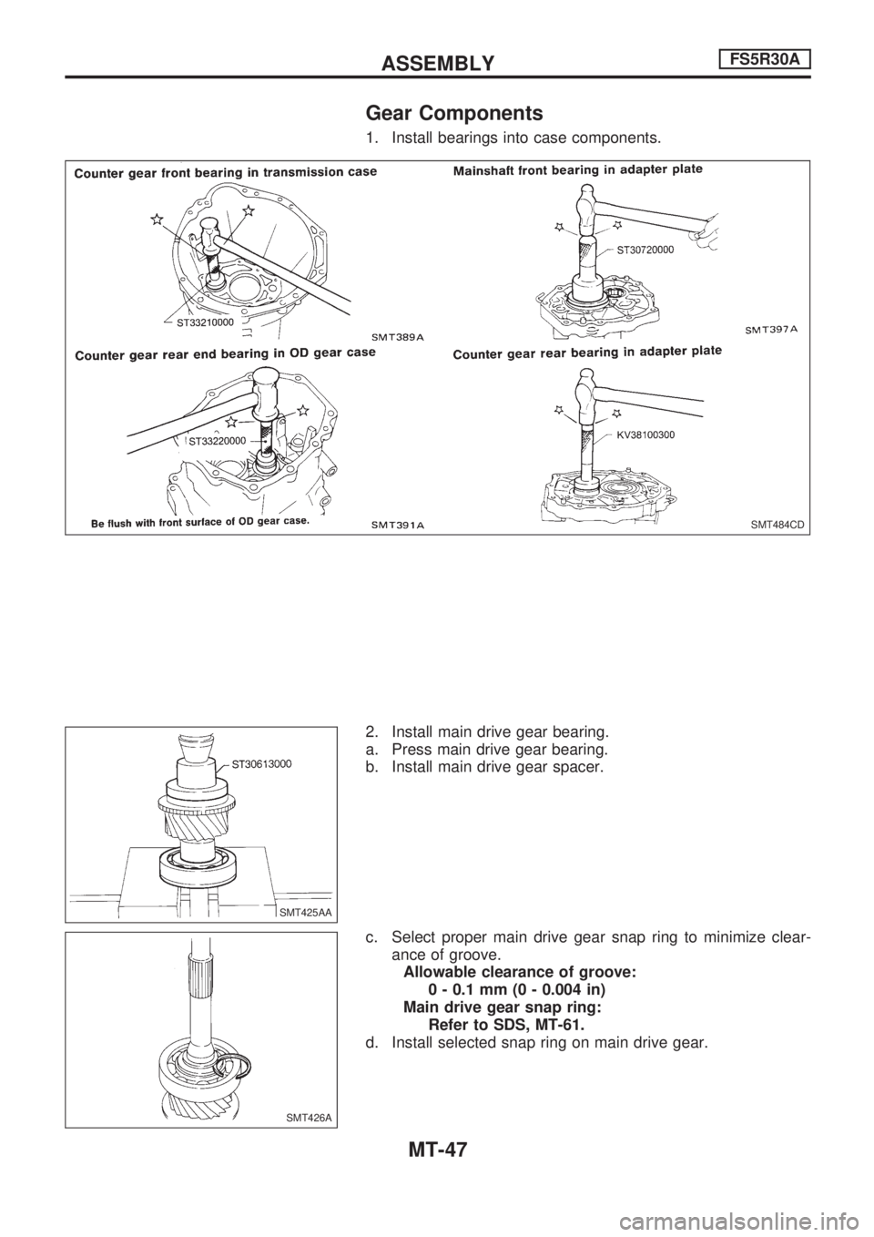
Gear Components
1. Install bearings into case components.
2. Install main drive gear bearing.
a. Press main drive gear bearing.
b. Install main drive gear spacer.
c. Select proper main drive gear snap ring to minimize clear-
ance of groove.
Allowable clearance of groove:
0 - 0.1 mm (0 - 0.004 in)
Main drive gear snap ring:
Refer to SDS, MT-61.
d. Install selected snap ring on main drive gear.
SMT484CD
SMT425AA
SMT426A
ASSEMBLYFS5R30A
MT-47
Page 1065 of 1659
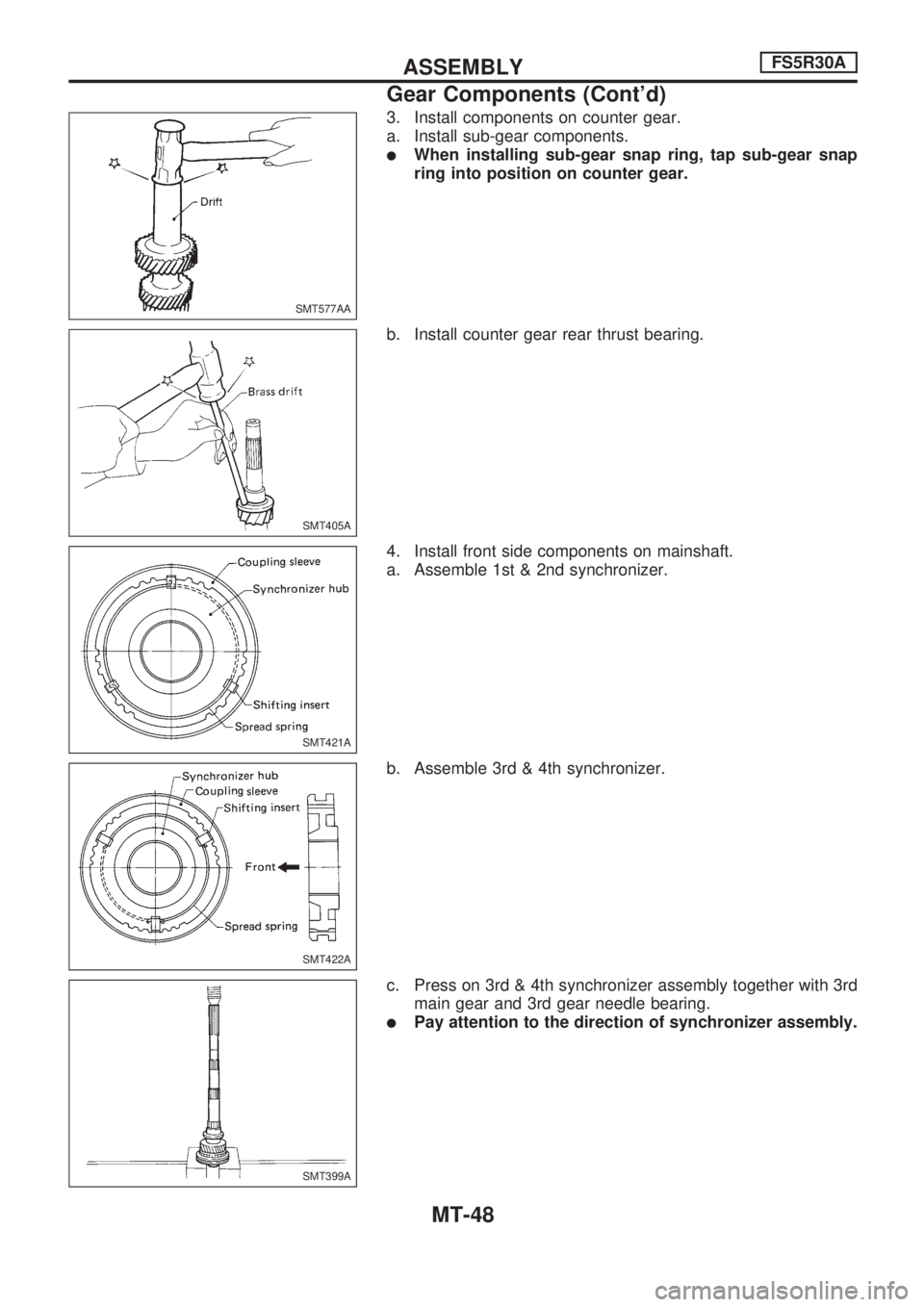
3. Install components on counter gear.
a. Install sub-gear components.
lWhen installing sub-gear snap ring, tap sub-gear snap
ring into position on counter gear.
b. Install counter gear rear thrust bearing.
4. Install front side components on mainshaft.
a. Assemble 1st & 2nd synchronizer.
b. Assemble 3rd & 4th synchronizer.
c. Press on 3rd & 4th synchronizer assembly together with 3rd
main gear and 3rd gear needle bearing.
lPay attention to the direction of synchronizer assembly.
SMT577AA
SMT405A
SMT421A
SMT422A
SMT399A
ASSEMBLYFS5R30A
Gear Components (Cont'd)
MT-48
Page 1066 of 1659
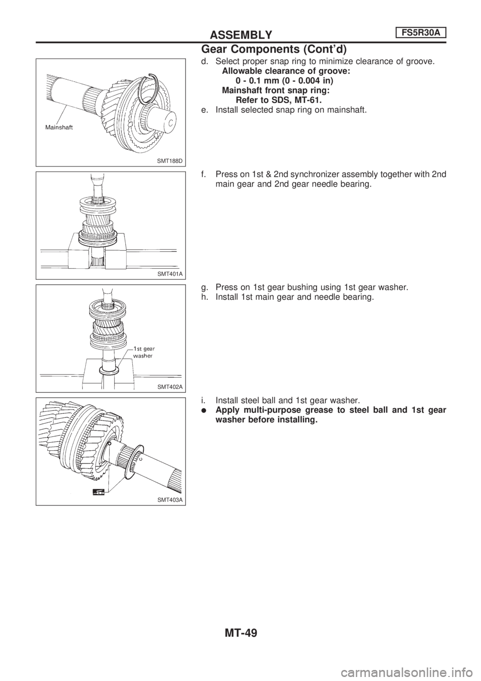
d. Select proper snap ring to minimize clearance of groove.
Allowable clearance of groove:
0 - 0.1 mm (0 - 0.004 in)
Mainshaft front snap ring:
Refer to SDS, MT-61.
e. Install selected snap ring on mainshaft.
f. Press on 1st & 2nd synchronizer assembly together with 2nd
main gear and 2nd gear needle bearing.
g. Press on 1st gear bushing using 1st gear washer.
h. Install 1st main gear and needle bearing.
i. Install steel ball and 1st gear washer.
lApply multi-purpose grease to steel ball and 1st gear
washer before installing.
SMT188D
SMT401A
SMT402A
SMT403A
ASSEMBLYFS5R30A
Gear Components (Cont'd)
MT-49
Page 1067 of 1659
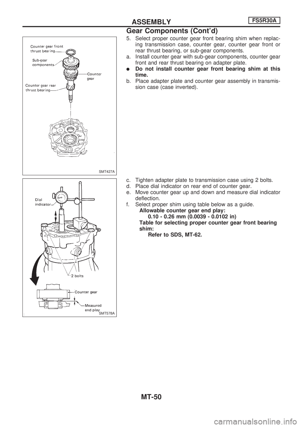
5. Select proper counter gear front bearing shim when replac-
ing transmission case, counter gear, counter gear front or
rear thrust bearing, or sub-gear components.
a. Install counter gear with sub-gear components, counter gear
front and rear thrust bearing on adapter plate.
lDo not install counter gear front bearing shim at this
time.
b. Place adapter plate and counter gear assembly in transmis-
sion case (case inverted).
c. Tighten adapter plate to transmission case using 2 bolts.
d. Place dial indicator on rear end of counter gear.
e. Move counter gear up and down and measure dial indicator
deflection.
f. Select proper shim using table below as a guide.
Allowable counter gear end play:
0.10 - 0.26 mm (0.0039 - 0.0102 in)
Table for selecting proper counter gear front bearing
shim:
Refer to SDS, MT-62.
SMT427A
SMT578A
ASSEMBLYFS5R30A
Gear Components (Cont'd)
MT-50
Page 1068 of 1659
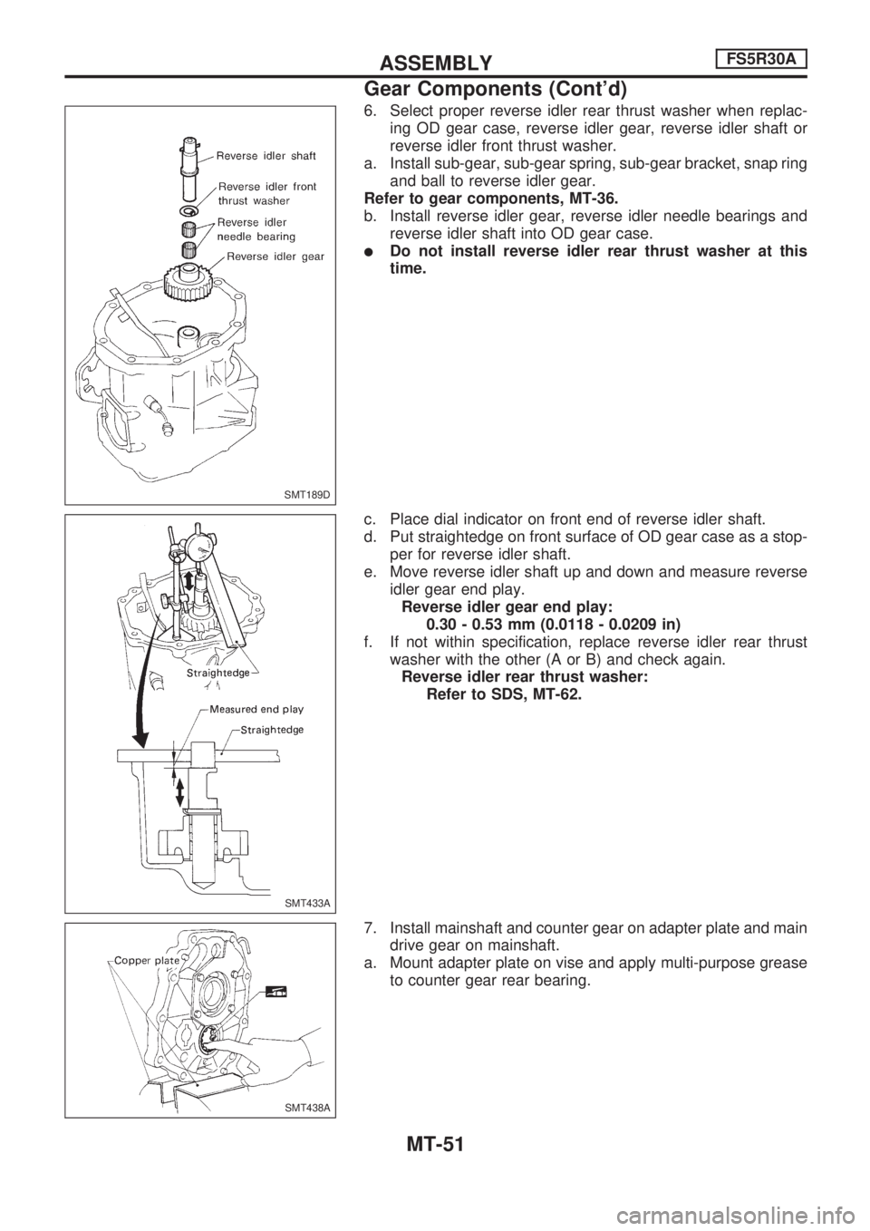
6. Select proper reverse idler rear thrust washer when replac-
ing OD gear case, reverse idler gear, reverse idler shaft or
reverse idler front thrust washer.
a. Install sub-gear, sub-gear spring, sub-gear bracket, snap ring
and ball to reverse idler gear.
Refer to gear components, MT-36.
b. Install reverse idler gear, reverse idler needle bearings and
reverse idler shaft into OD gear case.
lDo not install reverse idler rear thrust washer at this
time.
c. Place dial indicator on front end of reverse idler shaft.
d. Put straightedge on front surface of OD gear case as a stop-
per for reverse idler shaft.
e. Move reverse idler shaft up and down and measure reverse
idler gear end play.
Reverse idler gear end play:
0.30 - 0.53 mm (0.0118 - 0.0209 in)
f. If not within specification, replace reverse idler rear thrust
washer with the other (A or B) and check again.
Reverse idler rear thrust washer:
Refer to SDS, MT-62.
7. Install mainshaft and counter gear on adapter plate and main
drive gear on mainshaft.
a. Mount adapter plate on vise and apply multi-purpose grease
to counter gear rear bearing.
SMT189D
SMT433A
SMT438A
ASSEMBLYFS5R30A
Gear Components (Cont'd)
MT-51
Page 1069 of 1659
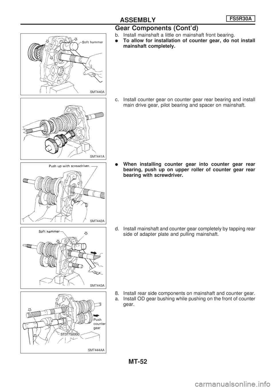
b. Install mainshaft a little on mainshaft front bearing.
lTo allow for installation of counter gear, do not install
mainshaft completely.
c. Install counter gear on counter gear rear bearing and install
main drive gear, pilot bearing and spacer on mainshaft.
lWhen installing counter gear into counter gear rear
bearing, push up on upper roller of counter gear rear
bearing with screwdriver.
d. Install mainshaft and counter gear completely by tapping rear
side of adapter plate and pulling mainshaft.
8. Install rear side components on mainshaft and counter gear.
a. Install OD gear bushing while pushing on the front of counter
gear.
SMT440A
SMT441A
SMT442A
SMT443A
SMT444AA
ASSEMBLYFS5R30A
Gear Components (Cont'd)
MT-52
Page 1070 of 1659
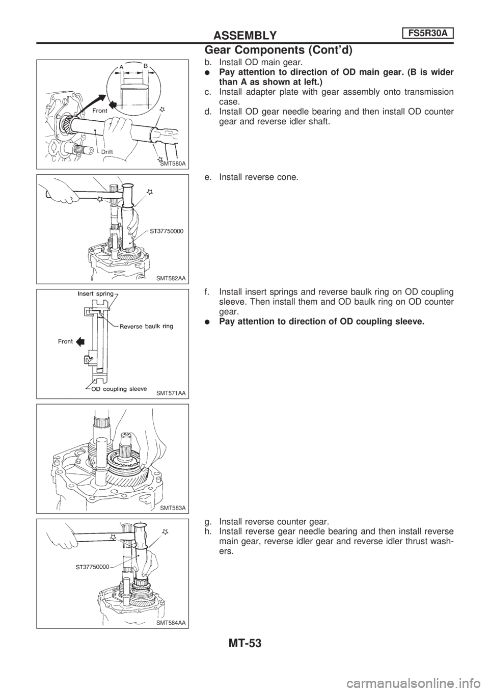
b. Install OD main gear.
lPay attention to direction of OD main gear. (B is wider
than A as shown at left.)
c. Install adapter plate with gear assembly onto transmission
case.
d. Install OD gear needle bearing and then install OD counter
gear and reverse idler shaft.
e. Install reverse cone.
f. Install insert springs and reverse baulk ring on OD coupling
sleeve. Then install them and OD baulk ring on OD counter
gear.
lPay attention to direction of OD coupling sleeve.
g. Install reverse counter gear.
h. Install reverse gear needle bearing and then install reverse
main gear, reverse idler gear and reverse idler thrust wash-
ers.
SMT580A
SMT582AA
SMT571AA
SMT583A
SMT584AA
ASSEMBLYFS5R30A
Gear Components (Cont'd)
MT-53
Trending: remove seats, fuse box location, airbag off, display, brake, engine, key
