NISSAN TEANA 2008 Service Manual
Manufacturer: NISSAN, Model Year: 2008, Model line: TEANA, Model: NISSAN TEANA 2008Pages: 5121, PDF Size: 69.03 MB
Page 4981 of 5121
WCS
BCM (BODY CONTROL MODULE)
WCS-51
< ECU DIAGNOSIS >
C
D
E
F
G
H
I
J
K
L
MB A
O
P
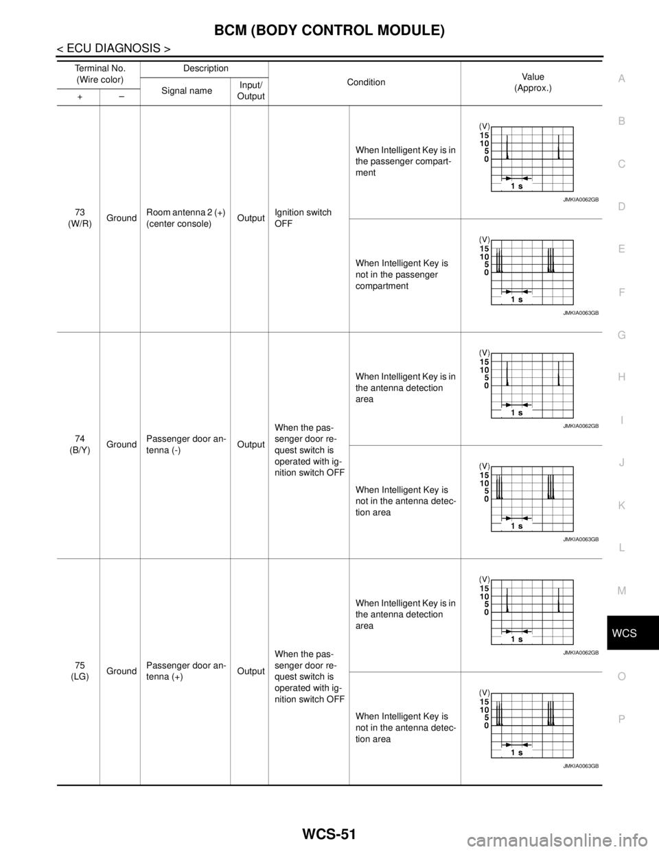
73
(W/R)GroundRoom antenna 2 (+)
(center console)OutputIgnition switch
OFFWhen Intelligent Key is in
the passenger compart-
ment
When Intelligent Key is
not in the passenger
compartment
74
(B/Y)GroundPassenger door an-
tenna (-)OutputWhen the pas-
senger door re-
quest switch is
operated with ig-
nition switch OFFWhen Intelligent Key is in
the antenna detection
area
When Intelligent Key is
not in the antenna detec-
tion area
75
(LG)GroundPassenger door an-
tenna (+)OutputWhen the pas-
senger door re-
quest switch is
operated with ig-
nition switch OFFWhen Intelligent Key is in
the antenna detection
area
When Intelligent Key is
not in the antenna detec-
tion area Te r m i n a l N o .
(Wire color)Description
ConditionVa l u e
(Approx.)
Signal nameInput/
Output +–
JMKIA0062GB
JMKIA0063GB
JMKIA0062GB
JMKIA0063GB
JMKIA0062GB
JMKIA0063GB
Page 4982 of 5121
WCS-52
< ECU DIAGNOSIS >
BCM (BODY CONTROL MODULE)
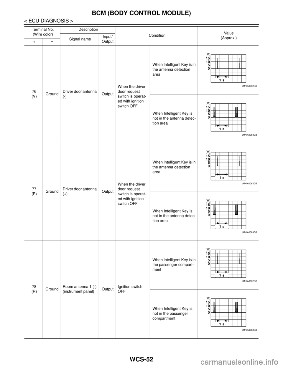
76
(V)GroundDriver door antenna
(-)OutputWhen the driver
door request
switch is operat-
ed with ignition
switch OFFWhen Intelligent Key is in
the antenna detection
area
When Intelligent Key is
not in the antenna detec-
tion area
77
(P)GroundDriver door antenna
(+)OutputWhen the driver
door request
switch is operat-
ed with ignition
switch OFFWhen Intelligent Key is in
the antenna detection
area
When Intelligent Key is
not in the antenna detec-
tion area
78
(R)GroundRoom antenna 1 (-)
(instrument panel)OutputIgnition switch
OFFWhen Intelligent Key is in
the passenger compart-
ment
When Intelligent Key is
not in the passenger
compartment Te r m i n a l N o .
(Wire color)Description
ConditionVa l u e
(Approx.)
Signal nameInput/
Output +–
JMKIA0062GB
JMKIA0063GB
JMKIA0062GB
JMKIA0063GB
JMKIA0062GB
JMKIA0063GB
Page 4983 of 5121
WCS
BCM (BODY CONTROL MODULE)
WCS-53
< ECU DIAGNOSIS >
C
D
E
F
G
H
I
J
K
L
MB A
O
P
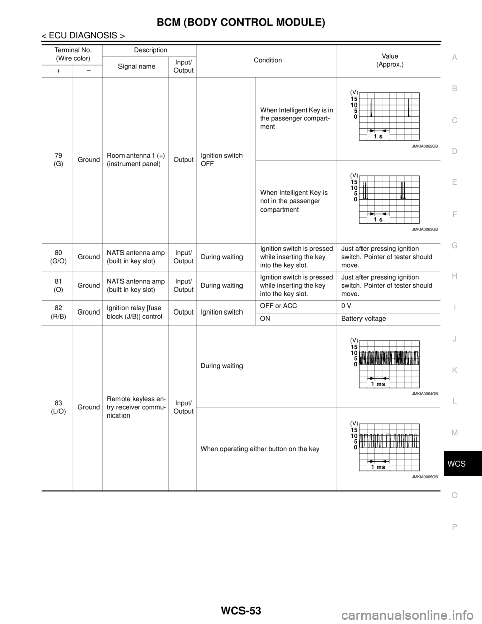
79
(G)GroundRoom antenna 1 (+)
(instrument panel)OutputIgnition switch
OFFWhen Intelligent Key is in
the passenger compart-
ment
When Intelligent Key is
not in the passenger
compartment
80
(G/O)GroundNATS antenna amp
(built in key slot)Input/
OutputDuring waitingIgnition switch is pressed
while inserting the key
into the key slot.Just after pressing ignition
switch. Pointer of tester should
move.
81
(O)GroundNATS antenna amp
(built in key slot)Input/
OutputDuring waitingIgnition switch is pressed
while inserting the key
into the key slot.Just after pressing ignition
switch. Pointer of tester should
move.
82
(R/B)GroundIgnition relay [fuse
block (J/B)] controlOutput Ignition switchOFF or ACC 0 V
ON Battery voltage
83
(L/O)GroundRemote keyless en-
try receiver commu-
nicationInput/
OutputDuring waiting
When operating either button on the key Te r m i n a l N o .
(Wire color)Description
ConditionVa l u e
(Approx.)
Signal nameInput/
Output +–
JMKIA0062GB
JMKIA0063GB
JMKIA0064GB
JMKIA0065GB
Page 4984 of 5121
WCS-54
< ECU DIAGNOSIS >
BCM (BODY CONTROL MODULE)
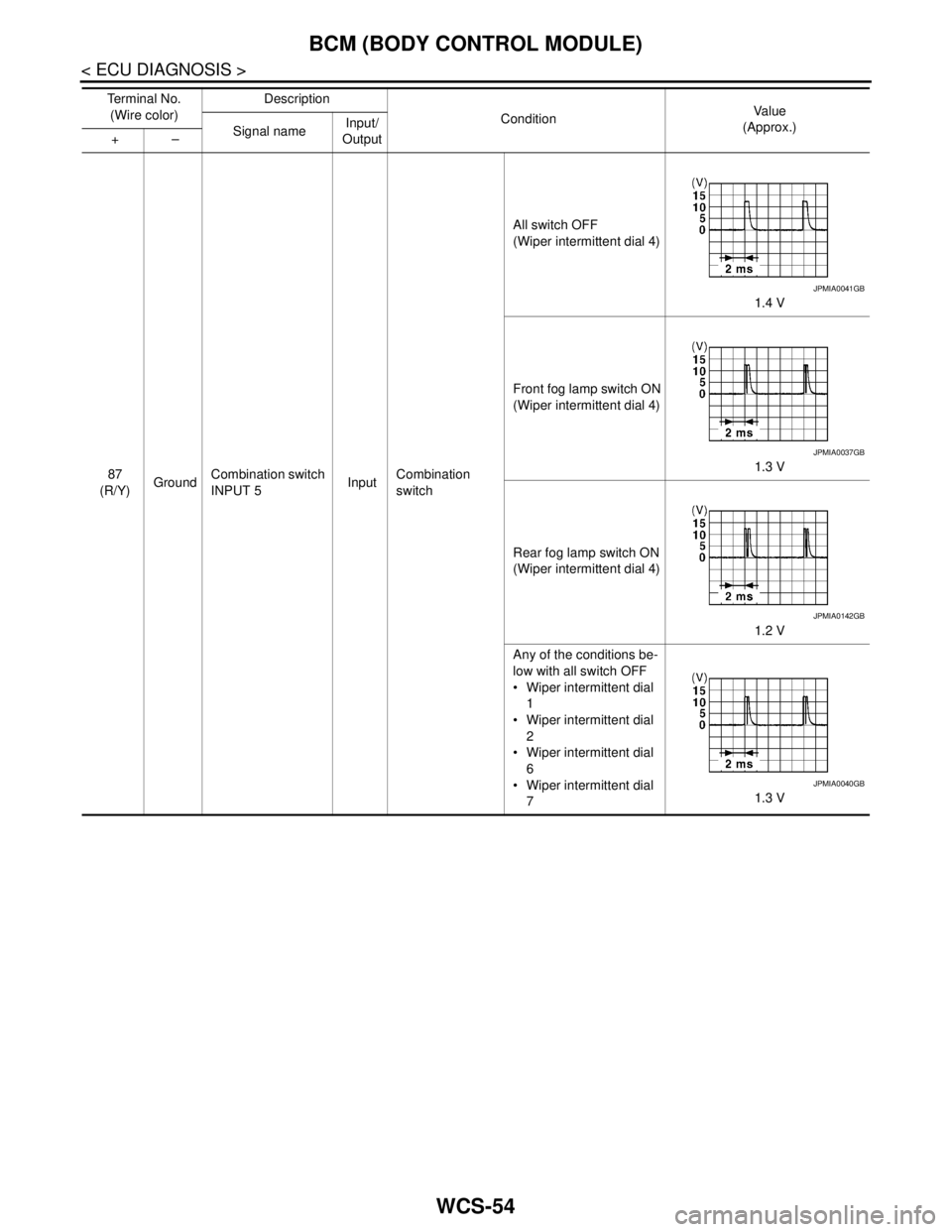
87
(R/Y)GroundCombination switch
INPUT 5InputCombination
switchAll switch OFF
(Wiper intermittent dial 4)
1.4 V
Front fog lamp switch ON
(Wiper intermittent dial 4)
1.3 V
Rear fog lamp switch ON
(Wiper intermittent dial 4)
1.2 V
Any of the conditions be-
low with all switch OFF
Wiper intermittent dial
1
Wiper intermittent dial
2
Wiper intermittent dial
6
Wiper intermittent dial
71.3 V Te r m i n a l N o .
(Wire color)Description
ConditionVa l u e
(Approx.)
Signal nameInput/
Output +–
JPMIA0041GB
JPMIA0037GB
JPMIA0142GB
JPMIA0040GB
Page 4985 of 5121
WCS
BCM (BODY CONTROL MODULE)
WCS-55
< ECU DIAGNOSIS >
C
D
E
F
G
H
I
J
K
L
MB A
O
P
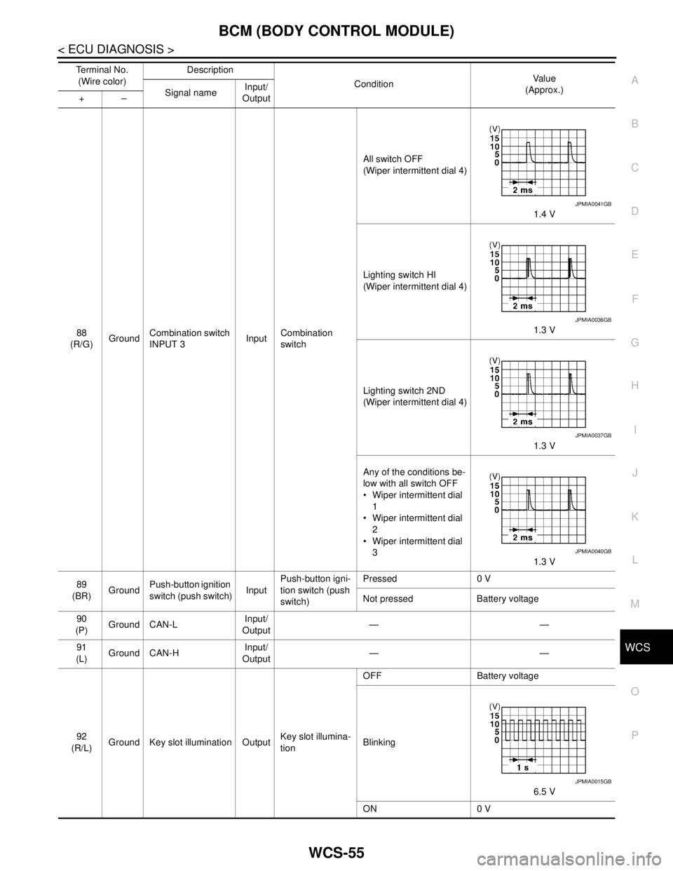
88
(R/G)GroundCombination switch
INPUT 3InputCombination
switchAll switch OFF
(Wiper intermittent dial 4)
1.4 V
Lighting switch HI
(Wiper intermittent dial 4)
1.3 V
Lighting switch 2ND
(Wiper intermittent dial 4)
1.3 V
Any of the conditions be-
low with all switch OFF
Wiper intermittent dial
1
Wiper intermittent dial
2
Wiper intermittent dial
3
1.3 V
89
(BR)GroundPush-button ignition
switch (push switch)InputPush-button igni-
tion switch (push
switch)Pressed 0 V
Not pressed Battery voltage
90
(P)Ground CAN-LInput/
Output——
91
(L)Ground CAN-HInput/
Output——
92
(R/L)Ground Key slot illumination OutputKey slot illumina-
tionOFF Battery voltage
Blinking
6.5 V
ON 0 V Te r m i n a l N o .
(Wire color)Description
ConditionVa l u e
(Approx.)
Signal nameInput/
Output +–
JPMIA0041GB
JPMIA0036GB
JPMIA0037GB
JPMIA0040GB
JPMIA0015GB
Page 4986 of 5121
WCS-56
< ECU DIAGNOSIS >
BCM (BODY CONTROL MODULE)
93
(Y)Ground ON indicator lamp Output Ignition switchOFF (LOCK indicator is
not illuminated)Battery voltage
ON or ACC 0 V
95
(L)Ground ACC relay control Output Ignition switchOFF 0 V
ACC or ON Battery voltage
96
(Y/R)GroundControl device (de-
tention switch) pow-
er supplyOutput — Battery voltage
97
(L/O)GroundSteering lock condi-
tion No. 1Input Steering lockLOCK status 0 V
UNLOCK status Battery voltage
98
(G/R)GroundSteering lock condi-
tion No. 2Input Steering lockLOCK status Battery voltage
UNLOCK status 0 V
99
(G/B)GroundSelector lever P po-
sition switchInput Selector leverP position 0 V
Any position other than P Battery voltage
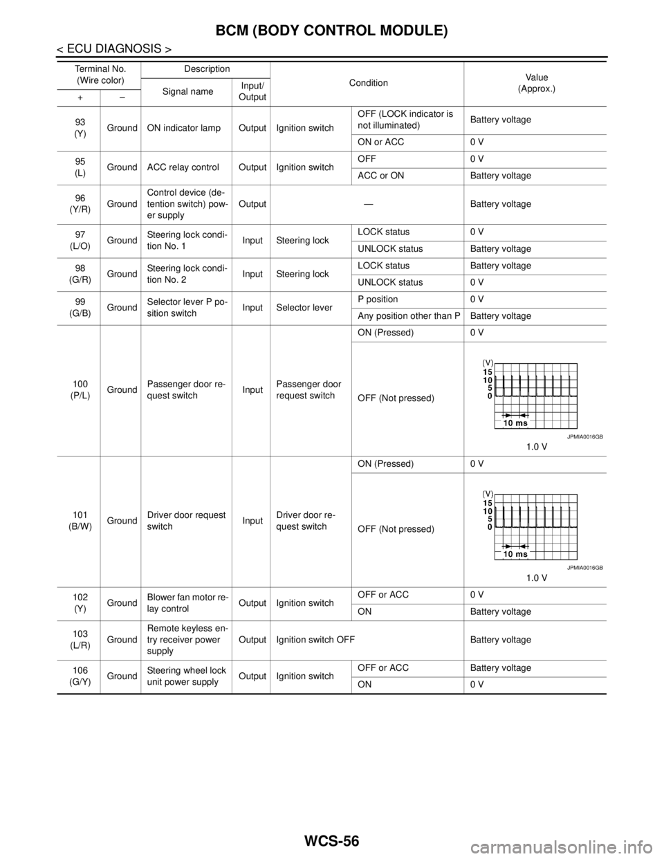
100
(P/L)GroundPassenger door re-
quest switchInputPassenger door
request switchON (Pressed) 0 V
OFF (Not pressed)
1.0 V
101
(B/W)GroundDriver door request
switchInputDriver door re-
quest switchON (Pressed) 0 V
OFF (Not pressed)
1.0 V
102
(Y)GroundBlower fan motor re-
lay controlOutput Ignition switchOFF or ACC 0 V
ON Battery voltage
103
(L/R)GroundRemote keyless en-
try receiver power
supplyOutput Ignition switch OFF Battery voltage
106
(G/Y)GroundSteering wheel lock
unit power supplyOutput Ignition switchOFF or ACC Battery voltage
ON 0 V Te r m i n a l N o .
(Wire color)Description
ConditionVa l u e
(Approx.)
Signal nameInput/
Output +–
JPMIA0016GB
JPMIA0016GB
Page 4987 of 5121
WCS
BCM (BODY CONTROL MODULE)
WCS-57
< ECU DIAGNOSIS >
C
D
E
F
G
H
I
J
K
L
MB A
O
P
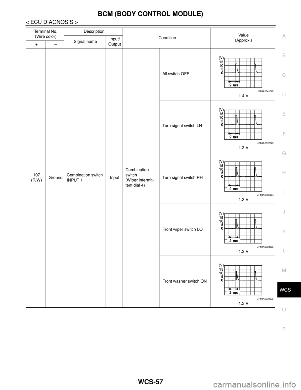
107
(R/W)GroundCombination switch
INPUT 1InputCombination
switch
(Wiper intermit-
tent dial 4)All switch OFF
1.4 V
Turn signal switch LH
1.3 V
Turn signal switch RH
1.3 V
Front wiper switch LO
1.3 V
Front washer switch ON
1.3 V Te r m i n a l N o .
(Wire color)Description
ConditionVa l u e
(Approx.)
Signal nameInput/
Output +–
JPMIA0041GB
JPMIA0037GB
JPMIA0036GB
JPMIA0038GB
JPMIA0039GB
Page 4988 of 5121
WCS-58
< ECU DIAGNOSIS >
BCM (BODY CONTROL MODULE)
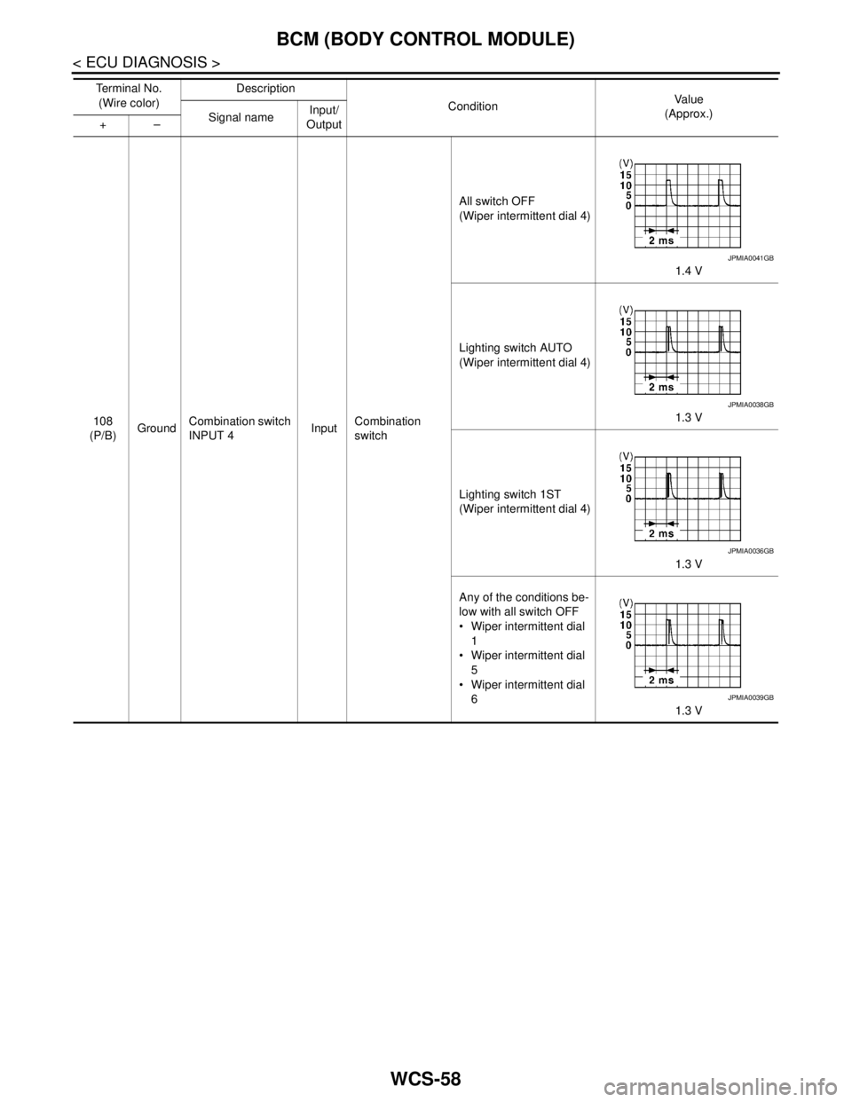
108
(P/B)GroundCombination switch
INPUT 4InputCombination
switchAll switch OFF
(Wiper intermittent dial 4)
1.4 V
Lighting switch AUTO
(Wiper intermittent dial 4)
1.3 V
Lighting switch 1ST
(Wiper intermittent dial 4)
1.3 V
Any of the conditions be-
low with all switch OFF
Wiper intermittent dial
1
Wiper intermittent dial
5
Wiper intermittent dial
6
1.3 V Te r m i n a l N o .
(Wire color)Description
ConditionVa l u e
(Approx.)
Signal nameInput/
Output +–
JPMIA0041GB
JPMIA0038GB
JPMIA0036GB
JPMIA0039GB
Page 4989 of 5121
WCS
BCM (BODY CONTROL MODULE)
WCS-59
< ECU DIAGNOSIS >
C
D
E
F
G
H
I
J
K
L
MB A
O
P
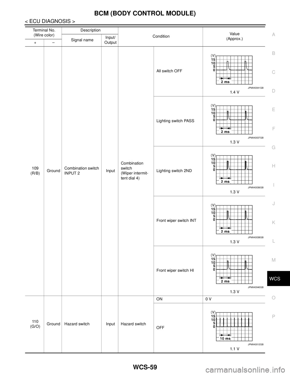
109
(R/B)GroundCombination switch
INPUT 2InputCombination
switch
(Wiper intermit-
tent dial 4)All switch OFF
1.4 V
Lighting switch PASS
1.3 V
Lighting switch 2ND
1.3 V
Front wiper switch INT
1.3 V
Front wiper switch HI
1.3 V
11 0
(G/O)Ground Hazard switch Input Hazard switchON 0 V
OFF
1.1 V Te r m i n a l N o .
(Wire color)Description
ConditionVa l u e
(Approx.)
Signal nameInput/
Output +–
JPMIA0041GB
JPMIA0037GB
JPMIA0036GB
JPMIA0038GB
JPMIA0040GB
JPMIA0012GB
Page 4990 of 5121
WCS-60
< ECU DIAGNOSIS >
BCM (BODY CONTROL MODULE)
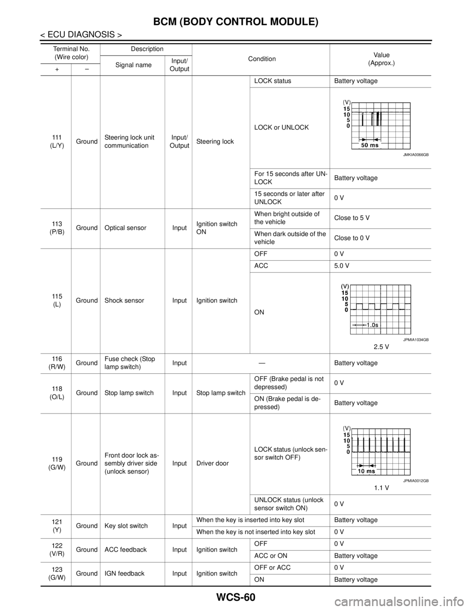
111
(L/Y)GroundSteering lock unit
communicationInput/
OutputSteering lockLOCK status Battery voltage
LOCK or UNLOCK
For 15 seconds after UN-
LOCKBattery voltage
15 seconds or later after
UNLOCK0 V
11 3
(P/B)Ground Optical sensor InputIgnition switch
ONWhen bright outside of
the vehicleClose to 5 V
When dark outside of the
vehicleClose to 0 V
11 5
(L)Ground Shock sensor Input Ignition switchOFF 0 V
ACC 5.0 V
ON
2.5 V
11 6
(R/W)GroundFuse check (Stop
lamp switch)Input — Battery voltage
11 8
(O/L)Ground Stop lamp switch Input Stop lamp switchOFF (Brake pedal is not
depressed)0 V
ON (Brake pedal is de-
pressed)Battery voltage
11 9
(G/W)GroundFront door lock as-
sembly driver side
(unlock sensor)Input Driver doorLOCK status (unlock sen-
sor switch OFF)
1.1 V
UNLOCK status (unlock
sensor switch ON)0 V
121
(Y)Ground Key slot switch InputWhen the key is inserted into key slot Battery voltage
When the key is not inserted into key slot 0 V
122
(V/R)Ground ACC feedback Input Ignition switchOFF 0 V
ACC or ON Battery voltage
123
(G/W)Ground IGN feedback Input Ignition switchOFF or ACC 0 V
ON Battery voltage Te r m i n a l N o .
(Wire color)Description
ConditionVa l u e
(Approx.)
Signal nameInput/
Output +–
JMKIA0066GB
JPMIA1034GB
JPMIA0012GB