NISSAN TERRANO 2004 Service Repair Manual
Manufacturer: NISSAN, Model Year: 2004, Model line: TERRANO, Model: NISSAN TERRANO 2004Pages: 1833, PDF Size: 53.42 MB
Page 811 of 1833
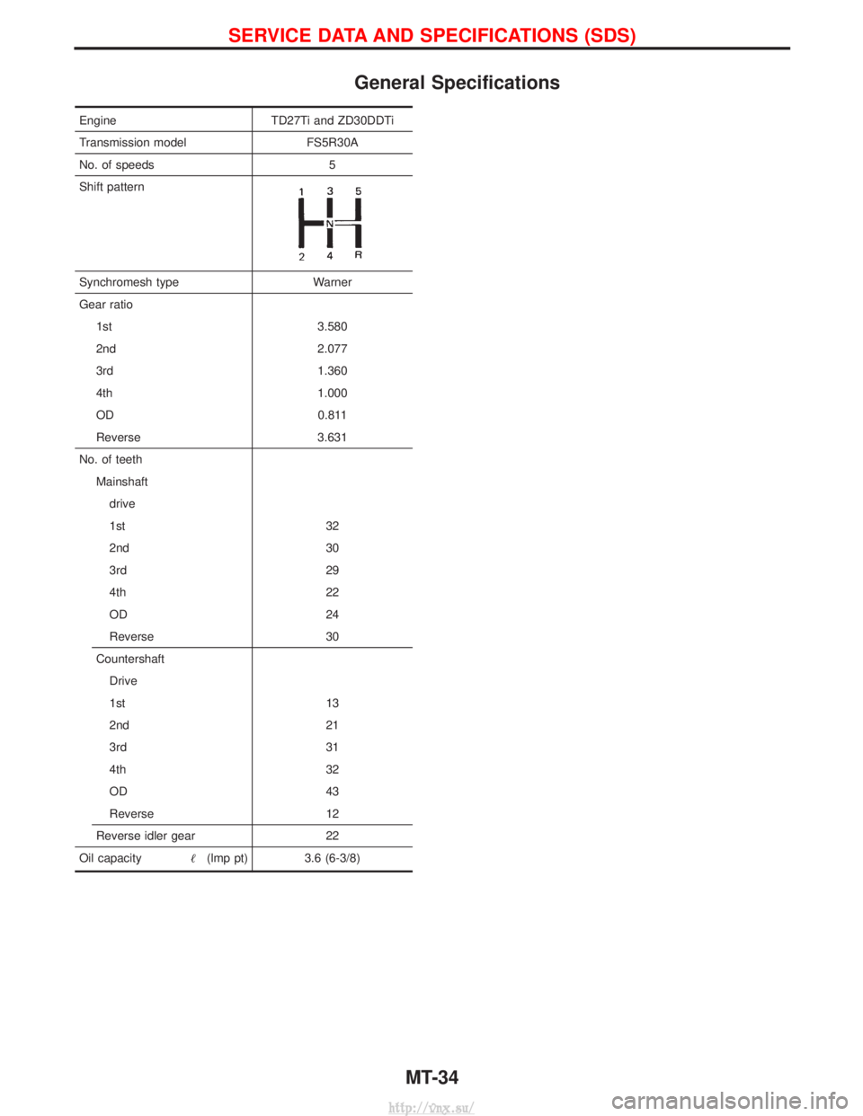
General Specifications
EngineTD27Ti and ZD30DDTi
Transmission model FS5R30A
No. of speeds 5
Shift pattern
Synchromesh type Warner
Gear ratio 1st 3.580
2nd 2.077
3rd 1.360
4th 1.000
OD 0.811
Reverse 3.631
No. of teeth Mainshaftdrive
1st 32
2nd 30
3rd 29
4th 22
OD 24
Reverse 30
Countershaft Drive
1st 13
2nd 21
3rd 31
4th 32
OD 43
Reverse 12
Reverse idler gear 22
Oil capacity (lmp pt) 3.6 (6-3/8)
SERVICE DATA AND SPECIFICATIONS (SDS)
MT-34
http://vnx.su/
Page 812 of 1833
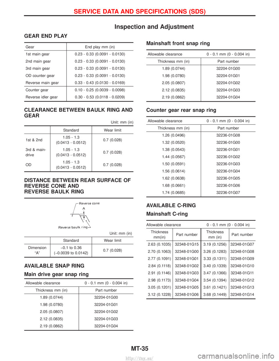
Inspection and Adjustment
GEAR END PLAY
GearEnd play mm (in)
1st main gear 0.23 - 0.33 (0.0091 - 0.0130)
2nd main gear 0.23 - 0.33 (0.0091 - 0.0130)
3rd main gear 0.23 - 0.33 (0.0091 - 0.0130)
OD counter gear 0.23 - 0.33 (0.0091 - 0.0130)
Reverse main gear 0.33 - 0.43 (0.0130 - 0.0169)
Counter gear 0.10 - 0.25 (0.0039 - 0.0098)
Reverse idler gear 0.30 - 0.53 (0.0118 - 0.0209)
CLEARANCE BETWEEN BAULK RING AND
GEAR
Unit: mm (in)
Standard Wear limit
1st & 2nd 1.05 - 1.3
(0.0413 - 0.0512) 0.7 (0.028)
3rd & main-
drive 1.05 - 1.3
(0.0413 - 0.0512) 0.7 (0.028)
OD 1.05 - 1.3
(0.0413 - 0.0512) 0.7 (0.028)
DISTANCE BETWEEN REAR SURFACE OF
REVERSE CONE AND
REVERSE BAULK RING
Unit: mm (in)
Standard Wear limit
Dimension ªAº þ0.1 to 0.36
(þ0.0039 to 0.0142) 0.7 (0.028)
AVAILABLE SNAP RING
Main drive gear snap ring
Allowable clearance
0 - 0.1 mm (0 - 0.004 in)
Thickness mm (in) Part number 1.89 (0.0744) 32204-01G00
1.98 (0.0780) 32204-01G01
2.05 (0.0807) 32204-01G02
2.12 (0.0835) 32204-01G03
2.19 (0.0862) 32204-01G04
Mainshaft front snap ring
Allowable clearance 0 - 0.1 mm (0 - 0.004 in)
Thickness mm (in) Part number 1.89 (0.0744) 32204-01G00
1.98 (0.0780) 32204-01G01
2.05 (0.0807) 32204-01G02
2.12 (0.0835) 32204-01G03
2.19 (0.0862) 32204-01G04
Counter gear rear snap ring
Allowable clearance 0 - 0.1 mm (0 - 0.004 in)
Thickness mm (in) Part number 1.26 (0.0496) 32236-01G08
1.32 (0.0520) 32236-01G00
1.38 (0.0543) 32236-01G01
1.44 (0.0567) 32236-01G02
1.50 (0.0591) 32236-01G03
1.56 (0.0614) 32236-01G04
1.62 (0.0638) 32236-01G05
1.68 (0.0661) 32236-01G06
1.74 (0.0685) 32236-01G07
AVAILABLE C-RING
Mainshaft C-ring
Allowable clearance 0 - 0.1 mm (0 - 0.004 in)
Thickness mm(in) Part number Thickness
mm (in) Part number
2.63 (0.1035) 32348-01G15 3.19 (0.1256) 32348-01G07
2.70 (0.1063) 32348-01G00 3.26 (0.1283) 32348-01G08
2.77 (0.1091) 32348-01G01 3.33 (0.1311) 32348-01G09 2.84 (0.1118) 32348-01G02 3.40 (0.1339) 32348-01G10
2.91 (0.1146) 32348-01G03 3.47 (0.1366) 32348-01G11
2.98 (0.1173) 32348-01G04 3.54 (0.1394) 32348-01G12
3.05 (0.1201) 32348-01G05 3.61 (0.1421) 32348-01G13
3.12 (0.1228) 32348-01G06 3.68 (0.1449) 32348-01G14
SERVICE DATA AND SPECIFICATIONS (SDS)
MT-35
http://vnx.su/
Page 813 of 1833
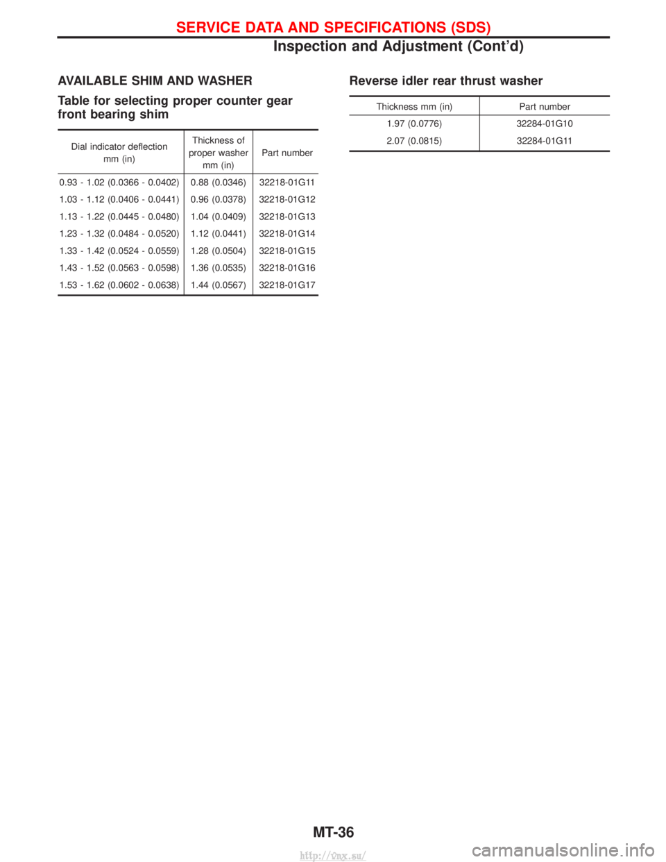
AVAILABLE SHIM AND WASHER
Table for selecting proper counter gear
front bearing shim
Dial indicator deflectionmm (in) Thickness of
proper washer mm (in) Part number
0.93 - 1.02 (0.0366 - 0.0402) 0.88 (0.0346) 32218-01G11
1.03 - 1.12 (0.0406 - 0.0441) 0.96 (0.0378) 32218-01G12
1.13 - 1.22 (0.0445 - 0.0480) 1.04 (0.0409) 32218-01G13
1.23 - 1.32 (0.0484 - 0.0520) 1.12 (0.0441) 32218-01G14
1.33 - 1.42 (0.0524 - 0.0559) 1.28 (0.0504) 32218-01G15
1.43 - 1.52 (0.0563 - 0.0598) 1.36 (0.0535) 32218-01G16
1.53 - 1.62 (0.0602 - 0.0638) 1.44 (0.0567) 32218-01G17
Reverse idler rear thrust washer
Thickness mm (in) Part number
1.97 (0.0776) 32284-01G10
2.07 (0.0815) 32284-01G11
SERVICE DATA AND SPECIFICATIONS (SDS)
Inspection and Adjustment (Cont'd)
MT-36
http://vnx.su/
Page 814 of 1833
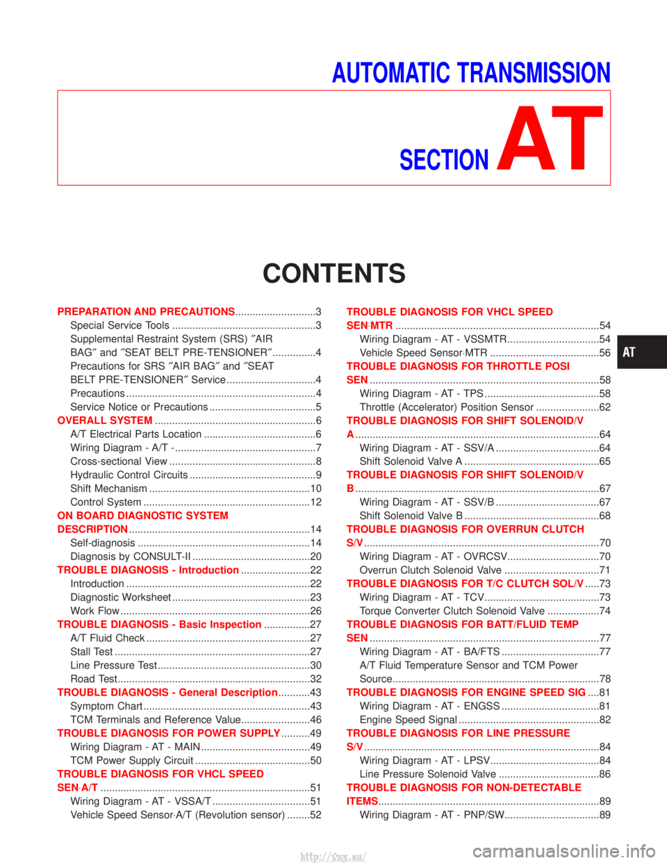
AUTOMATIC TRANSMISSIONSECTION
AT
CONTENTS
PREPARATION AND PRECAUTIONS ............................3
Special Service Tools ..................................................3
Supplemental Restraint System (SRS) ²AIR
BAG² and²SEAT BELT PRE-TENSIONER² ...............4
Precautions for SRS ²AIR BAG² and²SEAT
BELT PRE-TENSIONER² Service ...............................4
Precautions ..................................................................4
Service Notice or Precautions .....................................5
OVERALL SYSTEM ........................................................6
A/T Electrical Parts Location .......................................6
Wiring Diagram - A/T -.................................................7
Cross-sectional View ...................................................8
Hydraulic Control Circuits ............................................9
Shift Mechanism ........................................................10
Control System ..........................................................12
ON BOARD DIAGNOSTIC SYSTEM
DESCRIPTION ...............................................................14
Self-diagnosis ............................................................14
Diagnosis by CONSULT-II .........................................20
TROUBLE DIAGNOSIS - Introduction ........................22
Introduction ................................................................22
Diagnostic Worksheet ................................................23
Work Flow ..................................................................26
TROUBLE DIAGNOSIS - Basic Inspection ................27
A/T Fluid Check .........................................................27
Stall Test ....................................................................27
Line Pressure Test .....................................................30
Road Test...................................................................32
TROUBLE DIAGNOSIS - General Description ...........43
Symptom Chart ..........................................................43
TCM Terminals and Reference Value........................46
TROUBLE DIAGNOSIS FOR POWER SUPPLY ..........49
Wiring Diagram - AT - MAIN ......................................49
TCM Power Supply Circuit ........................................50
TROUBLE DIAGNOSIS FOR VHCL SPEED
SEN×A/T ........................................................................\
.51
Wiring Diagram - AT - VSSA/T ..................................51
Vehicle Speed Sensor×A/T (Revolution sensor) ........52 TROUBLE DIAGNOSIS FOR VHCL SPEED
SEN×MTR
.......................................................................54
Wiring Diagram - AT - VSSMTR ................................54
Vehicle Speed Sensor×MTR ......................................56
TROUBLE DIAGNOSIS FOR THROTTLE POSI
SEN ........................................................................\
........58
Wiring Diagram - AT - TPS ........................................58
Throttle (Accelerator) Position Sensor ......................62
TROUBLE DIAGNOSIS FOR SHIFT SOLENOID/V
A ........................................................................\
.............64
Wiring Diagram - AT - SSV/A ....................................64
Shift Solenoid Valve A ...............................................65
TROUBLE DIAGNOSIS FOR SHIFT SOLENOID/V
B ........................................................................\
.............67
Wiring Diagram - AT - SSV/B ....................................67
Shift Solenoid Valve B ...............................................68
TROUBLE DIAGNOSIS FOR OVERRUN CLUTCH
S/V ........................................................................\
..........70
Wiring Diagram - AT - OVRCSV................................70
Overrun Clutch Solenoid Valve .................................71
TROUBLE DIAGNOSIS FOR T/C CLUTCH SOL/V .....73
Wiring Diagram - AT - TCV........................................73
Torque Converter Clutch Solenoid Valve ..................74
TROUBLE DIAGNOSIS FOR BATT/FLUID TEMP
SEN ........................................................................\
........77
Wiring Diagram - AT - BA/FTS ..................................77
A/T Fluid Temperature Sensor and TCM Power
Source........................................................................\
78
TROUBLE DIAGNOSIS FOR ENGINE SPEED SIG ....81
Wiring Diagram - AT - ENGSS ..................................81
Engine Speed Signal .................................................82
TROUBLE DIAGNOSIS FOR LINE PRESSURE
S/V ........................................................................\
..........84
Wiring Diagram - AT - LPSV......................................84
Line Pressure Solenoid Valve ...................................86
TROUBLE DIAGNOSIS FOR NON-DETECTABLE
ITEMS........................................................................\
.....89 Wiring Diagram - AT - PNP/SW.................................89
http://vnx.su/
Page 815 of 1833
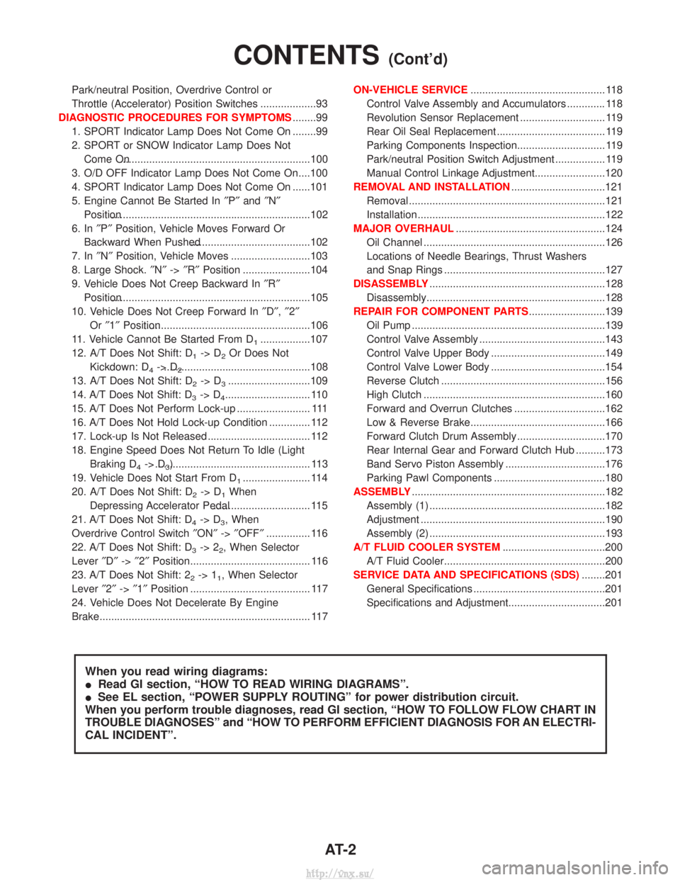
Park/neutral Position, Overdrive Control or
Throttle (Accelerator) Position Switches ...................93
DIAGNOSTIC PROCEDURES FOR SYMPTOMS ........99
1. SPORT Indicator Lamp Does Not Come On ........99
2. SPORT or SNOW Indicator Lamp Does Not Come On.................................................................100
3. O/D OFF Indicator Lamp Does Not Come On....100
4. SPORT Indicator Lamp Does Not Come On ......101
5. Engine Cannot Be Started In ²P² and ²N²
Position....................................................................102
6. In ²P² Position, Vehicle Moves Forward Or
Backward When Pushed.........................................102
7. In ²N² Position, Vehicle Moves ...........................103
8. Large Shock. ²N² ->²R² Position .......................104
9. Vehicle Does Not Creep Backward In ²R²
Position....................................................................105
10. Vehicle Does Not Creep Forward In ²D² ,²2²
Or ²1² Position.........................................................106
11. Vehicle Cannot Be Started From D
1.................107
12. A/T Does Not Shift: D
1-> D2Or Does Not
Kickdown: D
4-> D2..................................................108
13. A/T Does Not Shift: D
2-> D3............................109
14. A/T Does Not Shift: D
3-> D4............................. 110
15. A/T Does Not Perform Lock-up ......................... 111
16. A/T Does Not Hold Lock-up Condition .............. 112
17. Lock-up Is Not Released ................................... 112
18. Engine Speed Does Not Return To Idle (Light Braking D
4-> D3)..................................................... 113
19. Vehicle Does Not Start From D
1....................... 114
20. A/T Does Not Shift: D
2-> D1When
Depressing Accelerator Pedal................................. 115
21. A/T Does Not Shift: D
4-> D3, When
Overdrive Control Switch ²ON² ->²OFF² ............... 116
22. A/T Does Not Shift: D
3-> 22, When Selector
Lever ²D² ->²2² Position......................................... 116
23. A/T Does Not Shift: 2
2-> 11, When Selector
Lever ²2² ->²1² Position ......................................... 117
24. Vehicle Does Not Decelerate By Engine
Brake........................................................................\
117 ON-VEHICLE SERVICE
.............................................. 118
Control Valve Assembly and Accumulators ............. 118
Revolution Sensor Replacement ............................. 119
Rear Oil Seal Replacement ..................................... 119
Parking Components Inspection.............................. 119
Park/neutral Position Switch Adjustment ................. 119
Manual Control Linkage Adjustment........................120
REMOVAL AND INSTALLATION ................................121
Removal ...................................................................121
Installation ................................................................122
MAJOR OVERHAUL ...................................................124
Oil Channel ..............................................................126
Locations of Needle Bearings, Thrust Washers
and Snap Rings .......................................................127
DISASSEMBLY ............................................................128
Disassembly.............................................................128
REPAIR FOR COMPONENT PARTS ..........................139
Oil Pump ..................................................................139
Control Valve Assembly ...........................................143
Control Valve Upper Body .......................................149
Control Valve Lower Body .......................................154
Reverse Clutch ........................................................156
High Clutch ..............................................................160
Forward and Overrun Clutches ...............................162
Low & Reverse Brake..............................................166
Forward Clutch Drum Assembly ..............................170
Rear Internal Gear and Forward Clutch Hub ..........173
Band Servo Piston Assembly ..................................176
Parking Pawl Components ......................................180
ASSEMBLY ..................................................................182
Assembly (1) ............................................................182
Adjustment ...............................................................190
Assembly (2) ............................................................193
A/T FLUID COOLER SYSTEM ...................................200
A/T Fluid Cooler.......................................................200
SERVICE DATA AND SPECIFICATIONS (SDS) ........201
General Specifications .............................................201
Specifications and Adjustment.................................201
When you read wiring diagrams:
I Read GI section, ªHOW TO READ WIRING DIAGRAMSº.
I See EL section, ªPOWER SUPPLY ROUTINGº for power distribution circuit.
When you perform trouble diagnoses, read GI section, ªHOW TO FOLLOW FLOW CHART IN
TROUBLE DIAGNOSESº and ªHOW TO PERFORM EFFICIENT DIAGNOSIS FOR AN ELECTRI-
CAL INCIDENTº.
CONTENTS(Cont'd)
AT- 2
http://vnx.su/
Page 816 of 1833
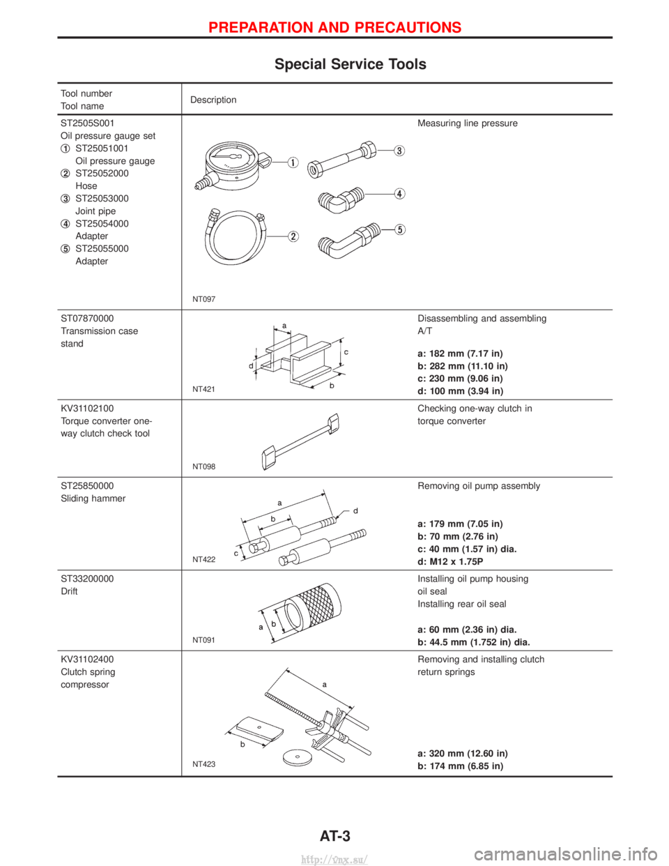
Special Service Tools
Tool number
Tool nameDescription
ST2505S001
Oil pressure gauge set
q
1ST25051001
Oil pressure gauge
q
2ST25052000
Hose
q
3ST25053000
Joint pipe
q
4ST25054000
Adapter
q
5ST25055000
Adapter
NT097
Measuring line pressure
ST07870000
Transmission case
stand
NT421
Disassembling and assembling
A/T
a: 182 mm (7.17 in)
b: 282 mm (11.10 in)
c: 230 mm (9.06 in)
d: 100 mm (3.94 in)
KV31102100
Torque converter one-
way clutch check tool
NT098
Checking one-way clutch in
torque converter
ST25850000
Sliding hammer
NT422
Removing oil pump assembly
a: 179 mm (7.05 in)
b: 70 mm (2.76 in)
c: 40 mm (1.57 in) dia.
d: M12 x 1.75P
ST33200000
Drift
NT091
Installing oil pump housing
oil seal
Installing rear oil seal
a: 60 mm (2.36 in) dia.
b: 44.5 mm (1.752 in) dia.
KV31102400
Clutch spring
compressor
NT423
Removing and installing clutch
return springs
a: 320 mm (12.60 in)
b: 174 mm (6.85 in)
PREPARATION AND PRECAUTIONS
AT- 3
http://vnx.su/
Page 817 of 1833
Supplemental Restraint System (SRS) ªAIR
BAGº and ªSEAT BELT PRE-TENSIONERº
The Supplemental Restraint System such as ªAIR BAGº and ªSEAT BELT PRE-TENSIONERº used along with
a seat belt, helps to reduce the risk or severity of injury to the driver and front passenger for certain types of
collision. The SRS composition which is available to NISSAN MODEL R20 is as follows (The composition
varies according to the destination and optional equipment.):
IFor a frontal collision
The Supplemental Restraint System consists of driver air bag module (located in the center of the steer-
ing wheel), front passenger air bag module (located on the instrument panel on passenger side), front seat
belt pre-tensioners, a diagnosis sensor unit, warning lamp, wiring harness and spiral cable.
I For a side collision
The Supplemental Restraint System consists of front side air bag module (located in the outer side of front
seat), side air bag (satellite) sensor, diagnosis sensor unit (one of components of air bags for a frontal
collision), wiring harness, warning lamp (one of components of air bags for a frontal collision).
WARNING:
I To avoid rendering the SRS inoperative, which could increase the risk of personal injury or death
in the event of a collision which would result in air bag inflation, all maintenance should be per-
formed by an authorized NISSAN dealer.
I Improper maintenance, including incorrect removal and installation of the SRS, can lead to per-
sonal injury caused by unintentional activation of the system.
I Do not use electrical test equipment on any circuit related to the SRS unless instructed to in this
Service Manual. Spiral cable and wiring harnesses covered with yellow insulation tape either just
before the harness connectors or for the complete harness are related to the SRS.
Precautions for SRS ªAIR BAGº and ªSEAT
BELT PRE-TENSIONERº Service
IDo not use electrical test equipment to check SRS circuits unless instructed to in this Service Manual.
I Before servicing the SRS, turn ignition switch ªOFFº, disconnect both battery cables and wait at least 3
minutes.
For approximately 3 minutes after the cables are removed, it is still possible for the air bag and seat belt
pre-tensioner to deploy. Therefore, do not work on any SRS connectors or wires until at least 3 minutes
have passed.
I Diagnosis sensor unit must always be installed with their arrow marks ª +º pointing towards the front of
the vehicle for proper operation. Also check diagnosis sensor unit for cracks, deformities or rust before
installation and replace as required.
I The spiral cable must be aligned with the neutral position since its rotations are limited. Do not attempt to
turn steering wheel or column after removal of steering gear.
I Handle air bag module carefully. Always place driver and front passenger air bag modules with the pad
side facing upward and place front side air bag module (built-in type) standing with stud bolt side setting
bottom.
I Conduct self-diagnosis to check entire SRS for proper function after replacing any components.
I After air bag inflates, the front instrument panel assembly should be replaced if damaged.
Precautions
IBefore proceeding with disassembly, thoroughly clean the outside of the transmission. It is important to
prevent the internal parts from becoming contaminated by dirt or other foreign matter.
I Disassembly should be done in a clean work area.
I Use lint-free cloth or towels for wiping parts clean. Common shop rags can leave fibers that could inter-
fere with the operation of the transmission.
I Place disassembled parts in order for easier and proper assembly.
I All parts should be carefully cleaned with a general purpose, non-flammable solvent before inspection or
reassembly.
I Gaskets, seals and O-rings should be replaced any time the transmission is disassembled.
I It is very important to perform functional tests whenever they are indicated.
I The valve body contains precision parts and requires extreme care when parts are removed and serviced.
Place removed parts in a parts rack in order to replace them in correct positions and sequences. Care will
also prevent springs and small parts from becoming scattered or lost.
I Properly installed valves, sleeves, plugs, etc. will slide along bores in valve body under their own weight.
PREPARATION AND PRECAUTIONS
AT- 4
http://vnx.su/
Page 818 of 1833
IBefore assembly, apply a coat of recommended ATF to all parts. Apply petroleum jelly to protect O-rings
and seals, and to hold bearings and washers in place during assembly. Do not use grease.
I Extreme care should be taken to avoid damage to O-rings, seals and gaskets when assembling.
I After overhaul, refill the transmission with new ATF.
I When the A/T drain plug is removed, only some of the fluid is drained. Old A/T fluid will remain in torque
converter and ATF cooling system.
Always follow the procedures under ªChanging A/T Fluidº in the MA section when changing A/T fluid.
Service Notice or Precautions
FAIL-SAFE
The TCM has an electronic Fail-Safe (limp home mode). This allows the vehicle to be driven even if a major
electrical input/output device circuit is damaged.
Under Fail-Safe, the vehicle always runs in third gear even with a shift lever position of ª1º, ª2º or ªDº. Cus-
tomer may complain of ªsluggish or poor accelerationº.
When the Fail-Safe operation occurs the next time the key is turned to the ªONº position, the SPORT indica-
tor lamp will blink for about 8 seconds. (For diagnosis, refer to AT-33.)
Fail-Safe may activate without electrical circuit damages if the vehicle is driven under extreme conditions (such
as excessive wheel spins and emergency braking immediately afterwards). In this case, turn the ignition key
ªOFFº for 5 seconds and then ªONº to recover normal shift pattern.
The blinking of the SPORT indicator lamp for about 8 seconds will appear only once and be cleared. The cus-
tomer may resume normal driving conditions by chance.
Always follow the ªWORK FLOWº (Refer to AT-26).
The SELF-DIAGNOSIS results will be as follows:
The first SELF-DIAGNOSIS will indicate the damage of the vehicle speed sensor or the revolution sensor.
During the next SELF-DIAGNOSIS performed after checking the sensor, no damages will be indicated.
PREPARATION AND PRECAUTIONS
Precautions (Cont'd)
AT- 5
http://vnx.su/
Page 819 of 1833
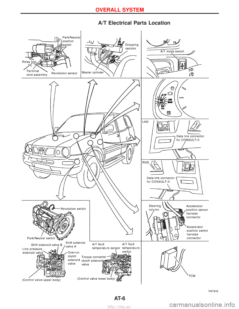
A/T Electrical Parts Location
YAT410
OVERALL SYSTEM
AT- 6
http://vnx.su/
Page 820 of 1833
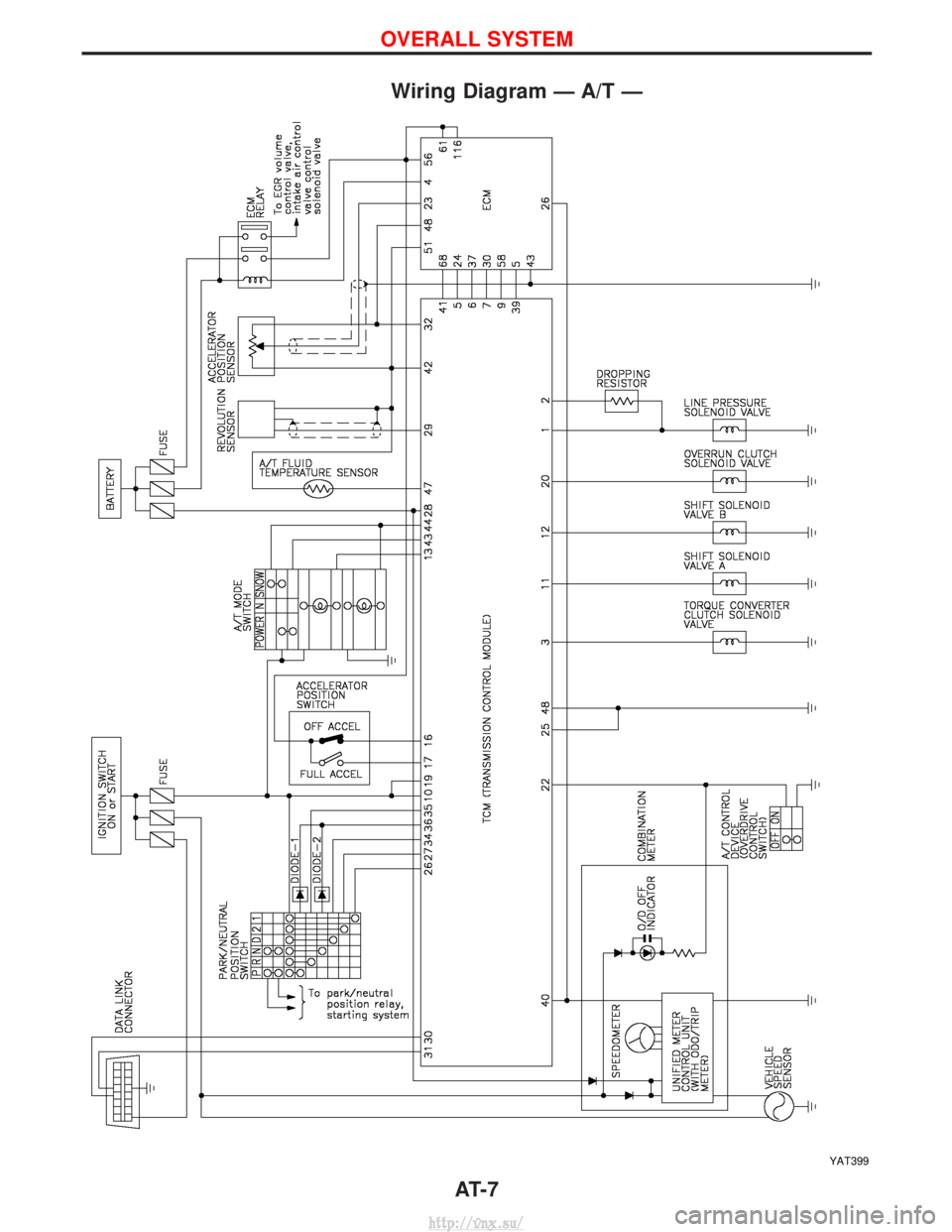
Wiring Diagram Ð A/T Ð
YAT399
OVERALL SYSTEM
AT- 7
http://vnx.su/