NISSAN X-TRAIL 2003 Electronic Repair Manual
Manufacturer: NISSAN, Model Year: 2003, Model line: X-TRAIL, Model: NISSAN X-TRAIL 2003Pages: 3066, PDF Size: 51.47 MB
Page 2341 of 3066

GW-38
POWER WINDOW SYSTEM
Trouble Diagnoses
EIS001SF
3 R/W Power window DOWN signalPower window switch DOWN
operation.Approx. 0
Power window switch
UP operation.Approx. 0
Power window switch DOWN
operation.Battery voltage
Power window switch
UP operation.Battery voltage
Other than above. Approx. 0
4 L/OR Power window UP signalPower window switch
UP operation.Approx. 0
Power window switch DOWN
operation.Approx. 0
Power window switch
UP operation.Battery voltage
Power window switch DOWN
operation.Battery voltage
Other than above. Approx. 0
5W/RPower window switch power
supply— Battery voltage TERMINALWIRE
COLORITEM CONDITION VOLTAGE (V)
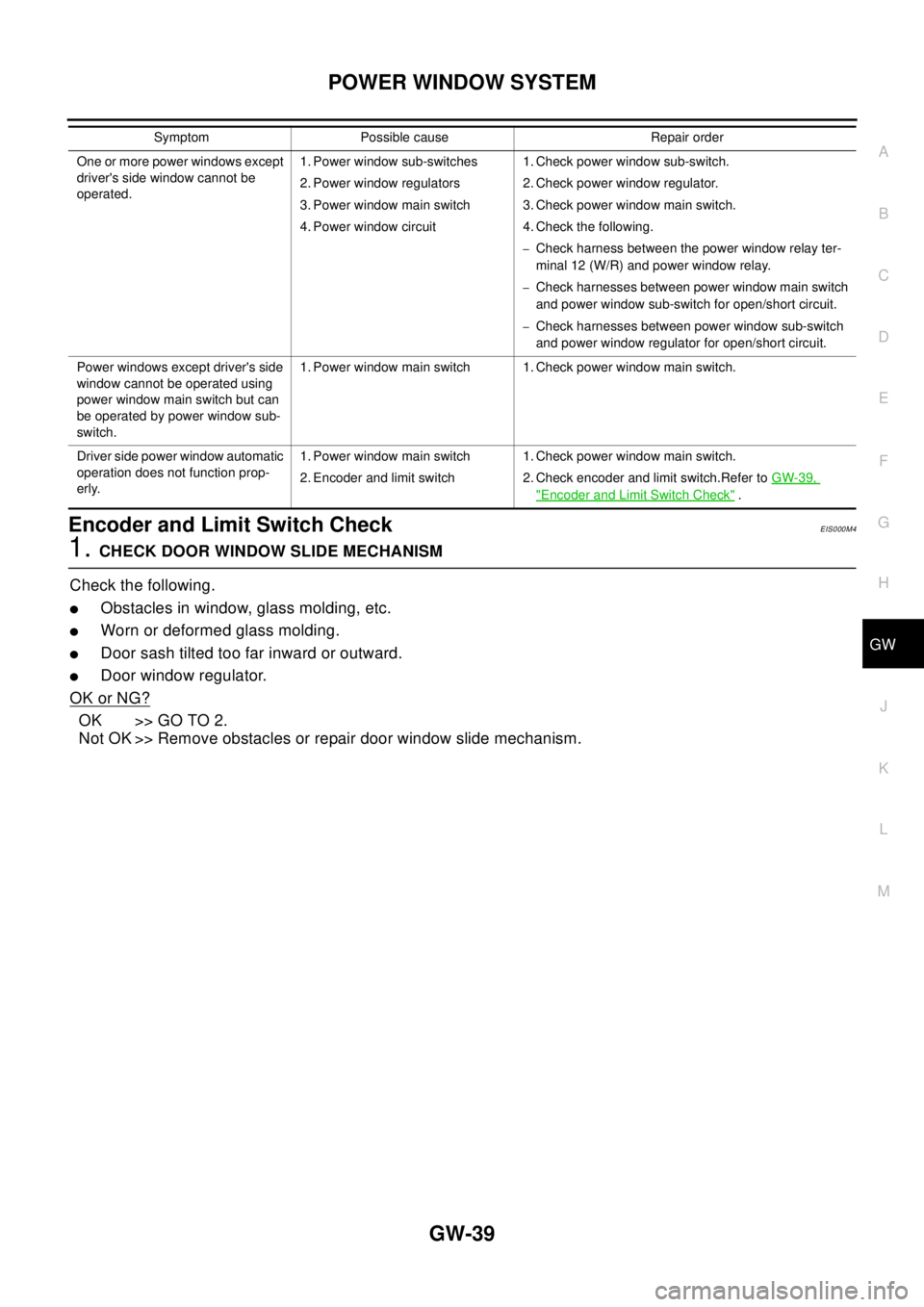
Symptom Possible cause Repair order
None of the power windows can be
operated using any switch.1. 10A fuse, 40A fusible link
2. M4 circuit breaker
3. Power window relay
4. M4 circuit breaker
5. Ground circuit
6. Power window main switch1. Check 10A fuse [No. 5, located in fuse block (J/B)]
Turn ignition switch “ON” and verify positive battery
voltage is present at terminal 1 (G) of power window
relay.
2. Check 40A fusible link (letterB, located in fuse and
fusible link box) and M4 circuit breaker. Verify positive
battery voltage is present at terminal 3 (W) of power
window relay.
3. Check M4 circuit breaker.
4. Check power window relay.
5. Check the following:
–Check harness between M4 circuit breaker and 40A
fusible link (letterB,located in fuse and fusible link
box).
–Check harness between M4 circuibt breaker and
power window main switch terminal 5 (LHD models)
or 3 (RHD models)
6. Check the following
–Check ground circuit of power window main switch.
–Check power window relay ground circuit.
–Check power window main switch.
Driver side power window cannot be
operated but other windows can be
operated.1. Driver side power window regula-
tor circuit
2. Driver side power window regula-
tor
3. Power window main switch1. Check harness between power window main switch
and driver side power window regulator for open or
short circuit.
2. Check driver side power window regulator.
3. Check power window main switch.
Page 2342 of 3066
POWER WINDOW SYSTEM
GW-39
C
D
E
F
G
H
J
K
L
MA
B
GW
Encoder and Limit Switch CheckEIS000M4
1.CHECK DOOR WINDOW SLIDE MECHANISM
Check the following.
lObstacles in window, glass molding, etc.
lWorn or deformed glass molding.
lDoor sash tilted too far inward or outward.
lDoor window regulator.
OK or NG?
OK >> GO TO 2.
Not OK >> Remove obstacles or repair door window slide mechanism.
One or more power windows except
driver's side window cannot be
operated.1. Power window sub-switches
2. Power window regulators
3. Power window main switch
4. Power window circuit1. Check power window sub-switch.
2. Check power window regulator.
3. Check power window main switch.
4. Check the following.
–Check harness between the power window relay ter-
minal 12 (W/R) and power window relay.
–Check harnesses between power window main switch
and power window sub-switch for open/short circuit.
–Check harnesses between power window sub-switch
and power window regulator for open/short circuit.
Power windows except driver's side
window cannot be operated using
power window main switch but can
be operated by power window sub-
switch.1. Power window main switch 1. Check power window main switch.
Driver side power window automatic
operation does not function prop-
erly.1. Power window main switch
2. Encoder and limit switch1. Check power window main switch.
2. Check encoder and limit switch.Refer toGW-39,
"Encoder and Limit Switch Check". Symptom Possible cause Repair order
Page 2343 of 3066
GW-40
POWER WINDOW SYSTEM
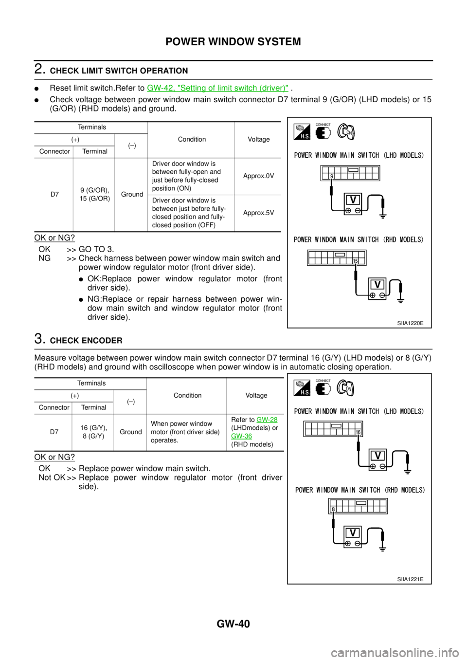
2.CHECK LIMIT SWITCH OPERATION
lReset limit switch.Refer toGW-42, "Setting of limit switch (driver)".
lCheck voltage between power window main switch connector D7 terminal 9 (G/OR) (LHD models) or 15
(G/OR) (RHD models) and ground.
OK or NG?
OK >> GO TO 3.
NG >> Check harness between power window main switch and
power window regulator motor (front driver side).
lOK:Replace power window regulator motor (front
driver side).
lNG:Replace or repair harness between power win-
dow main switch and window regulator motor (front
driver side).
3.CHECK ENCODER
Measure voltage between power window main switch connector D7 terminal 16 (G/Y) (LHD models) or 8 (G/Y)
(RHD models) and ground with oscilloscope when power window is in automatic closing operation.
OK or NG?
OK >> Replace power window main switch.
Not OK >> Replace power window regulator motor (front driver
side).
Te r m i n a l s
Condition Voltage (+)
(–)
Connector Terminal
D79 (G/OR),
15 (G/OR)GroundDriver door window is
between fully-open and
just before fully-closed
position (ON)Approx.0V
Driver door window is
between just before fully-
closed position and fully-
closed position (OFF)Approx.5V
SIIA1220E
Te r m i n a l s
Condition Voltage (+)
(–)
Connector Terminal
D716 (G/Y),
8(G/Y)GroundWhen power window
motor(frontdriverside)
operates.Refer toGW-28
(LHDmodels) or
GW-36
(RHD models)
SIIA1221E
Page 2344 of 3066
FRONT DOOR GLASS AND REGULATOR
GW-41
C
D
E
F
G
H
J
K
L
MA
B
GW
FRONTDOORGLASSANDREGULATORPFP:80300
Removal and InstallationEIS000MB
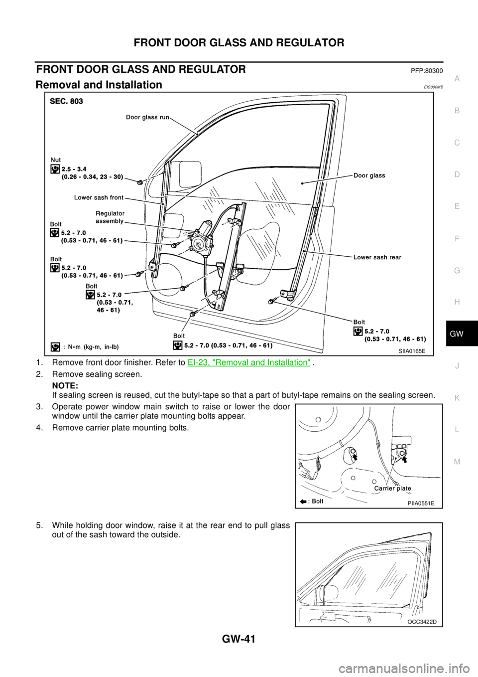
1. Remove front door finisher. Refer toEI-23, "Removal and Installation".
2. Remove sealing screen.
NOTE:
If sealing screen is reused, cut the butyl-tape so that a part of butyl-tape remains on the sealing screen.
3. Operate power window main switch to raise or lower the door
window until the carrier plate mounting bolts appear.
4. Remove carrier plate mounting bolts.
5. While holding door window, raise it at the rear end to pull glass
out of the sash toward the outside.
SIIA0165E
PIIA0551E
OCC3422D
Page 2345 of 3066
GW-42
FRONT DOOR GLASS AND REGULATOR
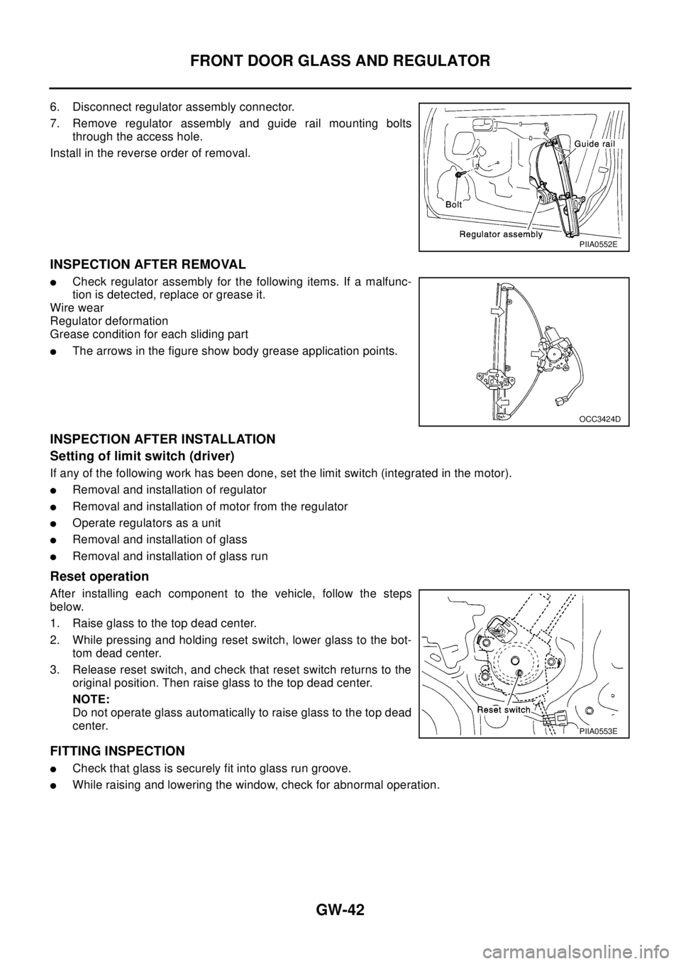
6. Disconnect regulator assembly connector.
7. Remove regulator assembly and guide rail mounting bolts
through the access hole.
Install in the reverse order of removal.
INSPECTION AFTER REMOVAL
lCheck regulator assembly for the following items. If a malfunc-
tion is detected, replace or grease it.
Wire wear
Regulator deformation
Grease condition for each sliding part
lThe arrows in the figure show body grease application points.
INSPECTION AFTER INSTALLATION
Setting of limit switch (driver)
If any of the following work has been done, set the limit switch (integrated in the motor).
lRemoval and installation of regulator
lRemoval and installation of motor from the regulator
lOperate regulators as a unit
lRemoval and installation of glass
lRemoval and installation of glass run
Reset operation
After installing each component to the vehicle, follow the steps
below.
1. Raise glass to the top dead center.
2. While pressing and holding reset switch, lower glass to the bot-
tom dead center.
3. Release reset switch, and check that reset switch returns to the
original position. Then raise glass to the top dead center.
NOTE:
Do not operate glass automatically to raise glass to the top dead
center.
FITTING INSPECTION
lCheck that glass is securely fit into glass run groove.
lWhile raising and lowering the window, check for abnormal operation.
PIIA0552E
OCC3424D
PIIA0553E
Page 2346 of 3066
REAR DOOR GLASS AND REGULATOR
GW-43
C
D
E
F
G
H
J
K
L
MA
B
GW
REAR DOOR GLASS AND REGULATORPFP:82300
Removal and InstallationEIS000MC
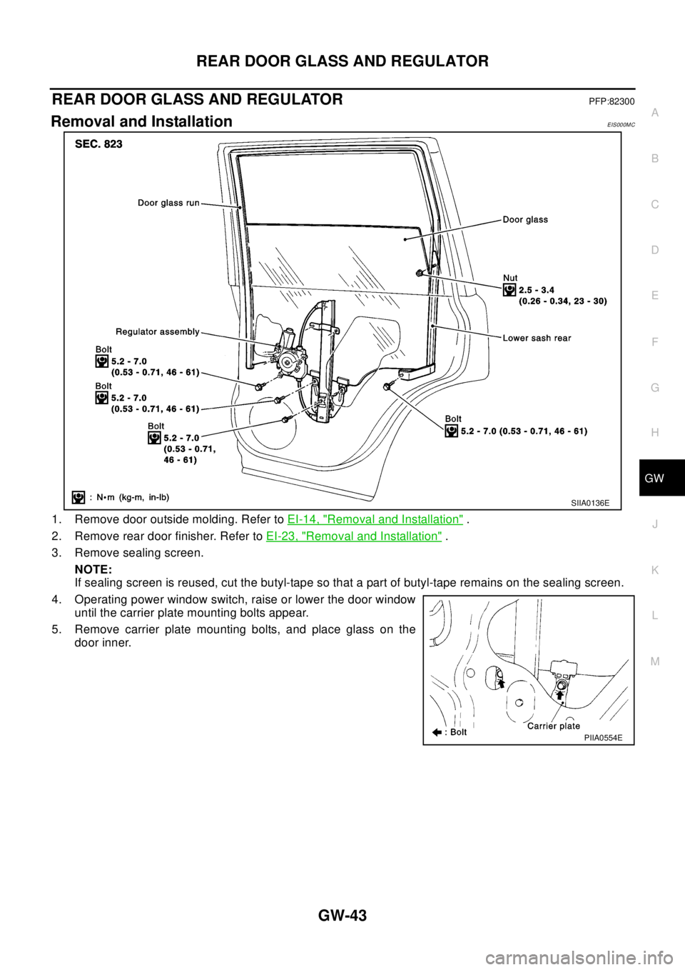
1. Remove door outside molding. Refer toEI-14, "Removal and Installation".
2. Remove rear door finisher. Refer toEI-23, "
Removal and Installation".
3. Remove sealing screen.
NOTE:
If sealing screen is reused, cut the butyl-tape so that a part of butyl-tape remains on the sealing screen.
4. Operating power window switch, raise or lower the door window
until the carrier plate mounting bolts appear.
5. Remove carrier plate mounting bolts, and place glass on the
door inner.
SIIA0136E
PIIA0554E
Page 2347 of 3066
GW-44
REAR DOOR GLASS AND REGULATOR
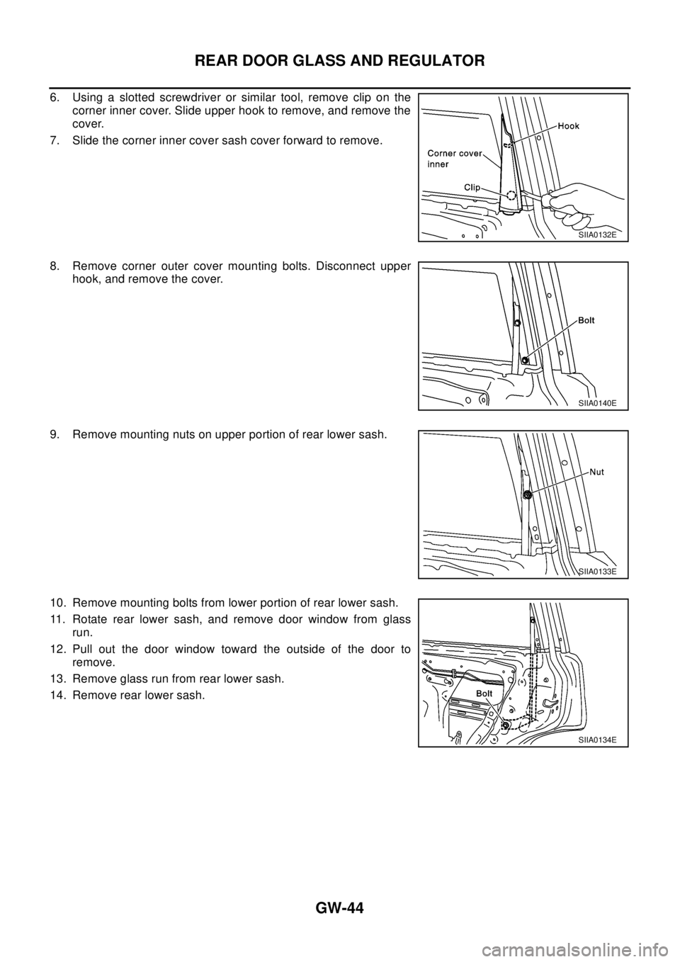
6. Using a slotted screwdriver or similar tool, remove clip on the
corner inner cover. Slide upper hook to remove, and remove the
cover.
7. Slide the corner inner cover sash cover forward to remove.
8. Remove corner outer cover mounting bolts. Disconnect upper
hook, and remove the cover.
9. Remove mounting nuts on upper portion of rear lower sash.
10. Remove mounting bolts from lower portion of rear lower sash.
11. Rotate rear lower sash, and remove door window from glass
run.
12. Pull out the door window toward the outside of the door to
remove.
13. Remove glass run from rear lower sash.
14. Remove rear lower sash.
SIIA0132E
SIIA0140E
SIIA0133E
SIIA0134E
Page 2348 of 3066
REAR DOOR GLASS AND REGULATOR
GW-45
C
D
E
F
G
H
J
K
L
MA
B
GW
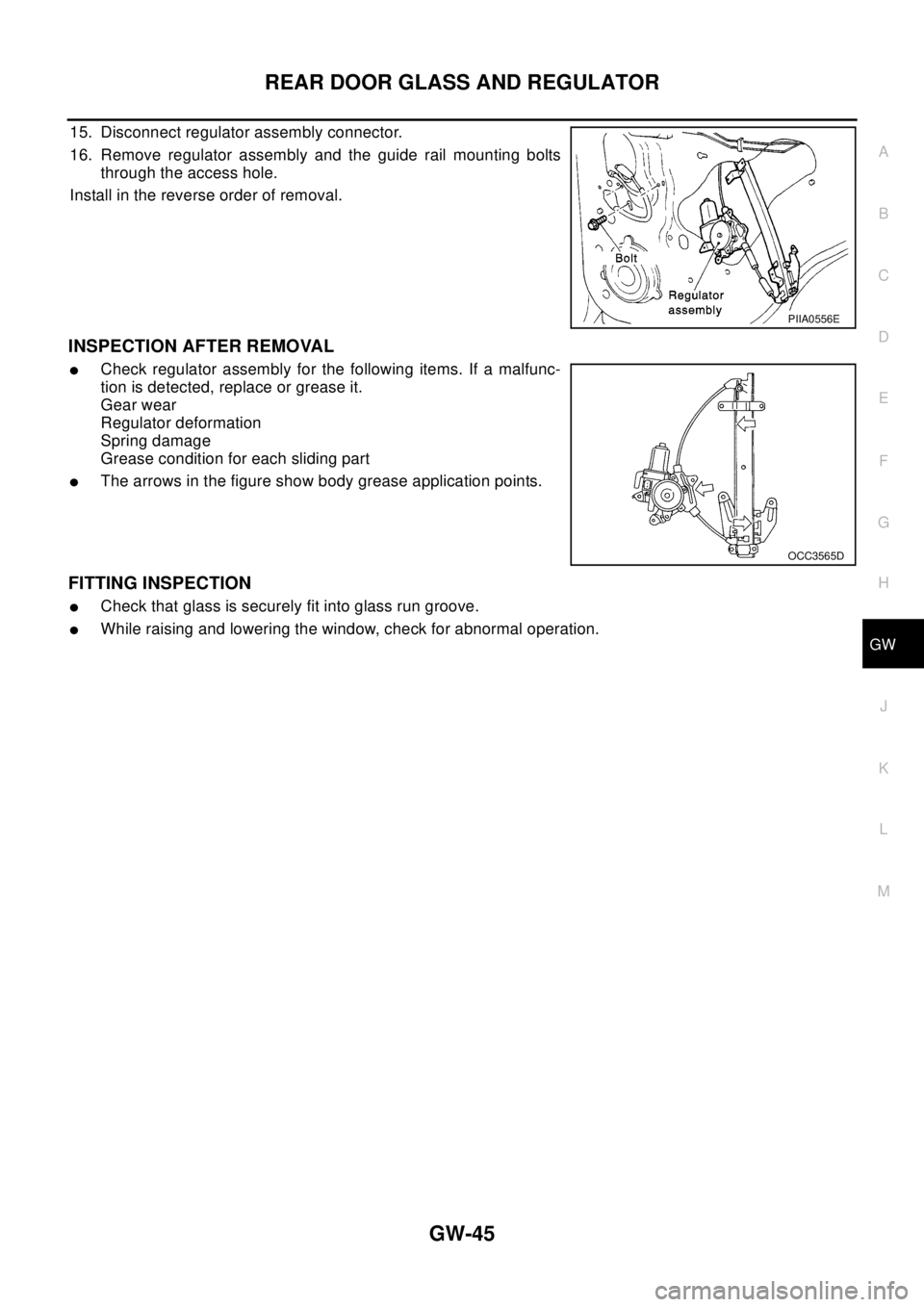
15. Disconnect regulator assembly connector.
16. Remove regulator assembly and the guide rail mounting bolts
through the access hole.
Install in the reverse order of removal.
INSPECTION AFTER REMOVAL
lCheck regulator assembly for the following items. If a malfunc-
tion is detected, replace or grease it.
Gear wear
Regulator deformation
Spring damage
Grease condition for each sliding part
lThe arrows in the figure show body grease application points.
FITTING INSPECTION
lCheck that glass is securely fit into glass run groove.
lWhile raising and lowering the window, check for abnormal operation.
PIIA0556E
OCC3565D
Page 2349 of 3066
GW-46
DOOR MIRROR
DOOR MIRROR
PFP:96301
Precautions to Handle Retractable Power Door MirrorsEIS000MD
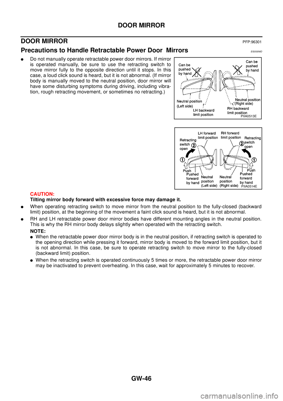
lDo not manually operate retractable power door mirrors. If mirror
is operated manually, be sure to use the retracting switch to
move mirror fully to the opposite direction until it stops. In this
case, a loud click sound is heard, but it is not abnormal. (If mirror
body is manually moved to the neutral position, door mirror will
have some disturbing symptoms during driving, including vibra-
tion, rough retracting movement, or sometimes no retracting.)
CAUTION:
Tilting mirror body forward with excessive force may damage it.
lWhen operating retracting switch to move mirror from the neutral position to the fully-closed (backward
limit) position, at the beginning of the movement a faint click sound is heard, but it is not abnormal.
lRH and LH retractable power door mirror bodies have different mounting angles in the neutral position.
This is why the RH mirror body delays slightly when operated with the retracting switch.
NOTE:
lWhen the retractable power door mirror body is in the neutral position, if retracting switch is operated to
the opening direction while pressing it forward, mirror body is moved to the forward limit position, but it
is not abnormal. In this case, be sure to operate retracting switch to move mirror to the fully-closed
(backward limit) position.
lWhen the retracting switch is operated continuously 5 times or more, the retractable power door mirror
may be inactivated to prevent overheating. In this case, wait for approximately 5 minutes to recover.
PIIA0513E
PIIA0514E
Page 2350 of 3066
DOOR MIRROR
GW-47
C
D
E
F
G
H
J
K
L
MA
B
GW
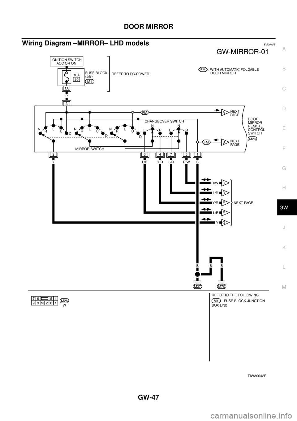
Wiring Diagram –MIRROR– LHD modelsEIS001SZ
TIWA0042E