NISSAN X-TRAIL 2003 Electronic Repair Manual
Manufacturer: NISSAN, Model Year: 2003, Model line: X-TRAIL, Model: NISSAN X-TRAIL 2003Pages: 3066, PDF Size: 51.47 MB
Page 2351 of 3066
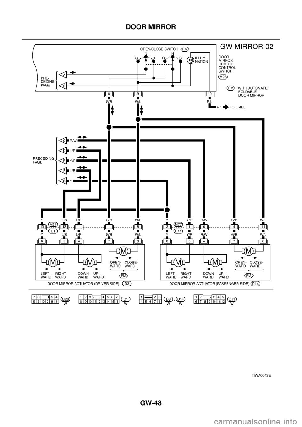
GW-48
DOOR MIRROR
TIWA0043E
Page 2352 of 3066
DOOR MIRROR
GW-49
C
D
E
F
G
H
J
K
L
MA
B
GW
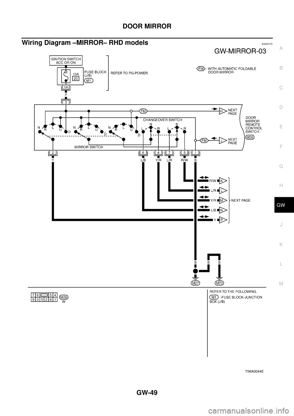
Wiring Diagram –MIRROR– RHD modelsEIS0 01T 0
TIWA0044E
Page 2353 of 3066
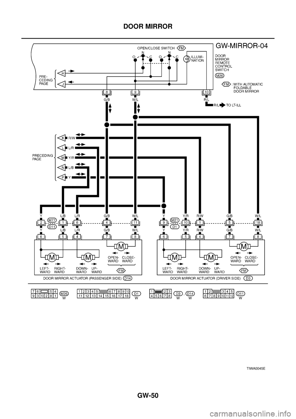
GW-50
DOOR MIRROR
TIWA0045E
Page 2354 of 3066
DOOR MIRROR
GW-51
C
D
E
F
G
H
J
K
L
MA
B
GW
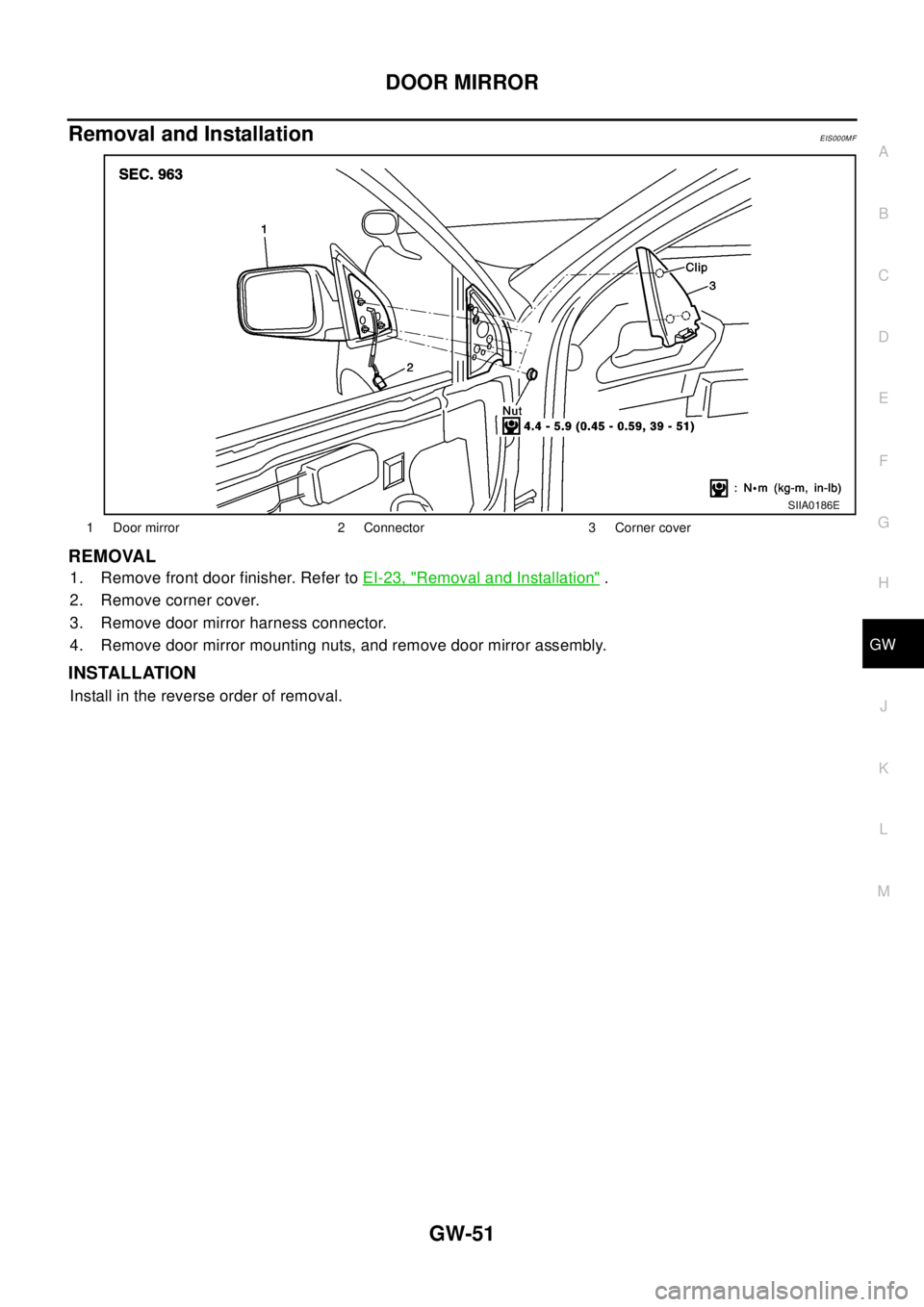
Removal and InstallationEIS000MF
REMOVAL
1. Remove front door finisher. Refer toEI-23, "Removal and Installation".
2. Remove corner cover.
3. Remove door mirror harness connector.
4. Remove door mirror mounting nuts, and remove door mirror assembly.
INSTALLATION
Install in the reverse order of removal.
1 Door mirror 2 Connector 3 Corner cover
SIIA0186E
Page 2355 of 3066
GW-52
DOOR MIRROR
Disassembly and Assembly
EIS000MG
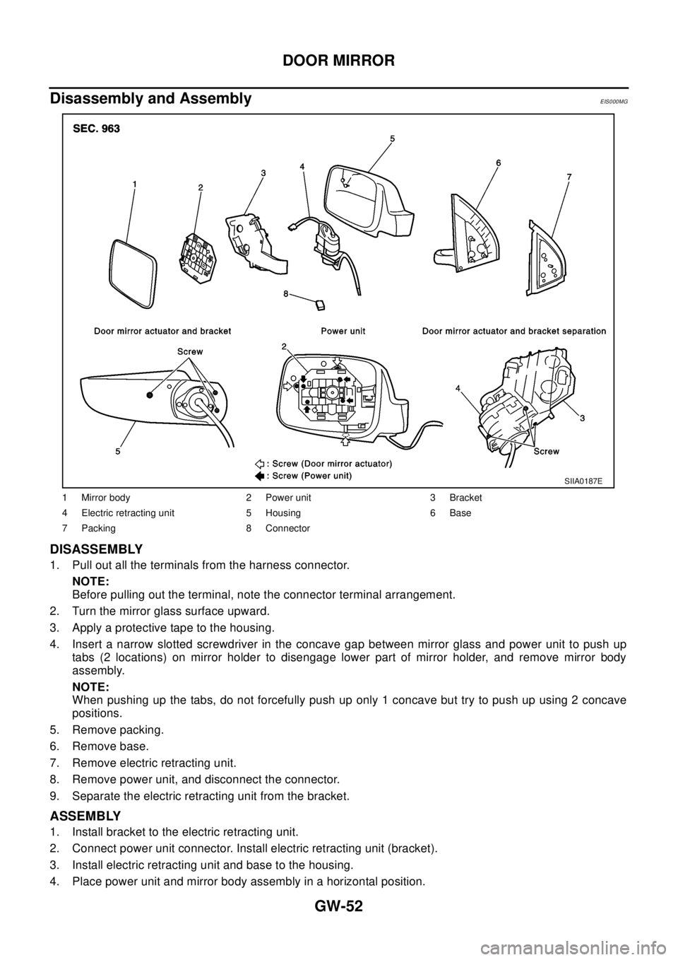
DISASSEMBLY
1. Pull out all the terminals from the harness connector.
NOTE:
Before pulling out the terminal, note the connector terminal arrangement.
2. Turn the mirror glass surface upward.
3. Apply a protective tape to the housing.
4. Insert a narrow slotted screwdriver in the concave gap between mirror glass and power unit to push up
tabs (2 locations) on mirror holder to disengage lower part of mirror holder, and remove mirror body
assembly.
NOTE:
When pushing up the tabs, do not forcefully push up only 1 concave but try to push up using 2 concave
positions.
5. Remove packing.
6. Remove base.
7. Remove electric retracting unit.
8. Remove power unit, and disconnect the connector.
9. Separate the electric retracting unit from the bracket.
ASSEMBLY
1. Install bracket to the electric retracting unit.
2. Connect power unit connector. Install electric retracting unit (bracket).
3. Install electric retracting unit and base to the housing.
4. Place power unit and mirror body assembly in a horizontal position.
1 Mirror body 2 Power unit 3 Bracket
4 Electric retracting unit 5 Housing 6 Base
7 Packing 8 Connector
SIIA0187E
Page 2356 of 3066
DOOR MIRROR
GW-53
C
D
E
F
G
H
J
K
L
MA
B
GW
5. Engage upper tabs of mirror glass with power unit. Then, press lower part of mirror glass down until the
lower part snaps to allow engagement of lower tabs.
NOTE:
After installation, visually check that the lower tabs (2) are securely engaged when viewed from the bot-
tom of mirror surface.
6. Install the packing to the base.
7. Insert the harness terminal into the connector.
NOTE:
Make sure to insert the harness terminal into the correct connector. Do not confuse the locations.
Page 2357 of 3066

GW-54
DOOR MIRROR
Page 2358 of 3066
IDX-1
A
C
D
E
F
G
H
I
J
K
L B
IDX
ALPHABETICAL INDEX
MINDEX
SECTION
Page 2359 of 3066
IDX-2
ALPHABETICAL INDEX
Numerics
4WD mode switch ...................................TF-53
,TF-57
4WD shift indicator lamp .........................TF-32,TF-54
4WD solenoid valve ................................TF-49,TF-51
4WD warning lamp ..........TF-32,TF-40,TF-55,TF-58
A
A/C air flow .........................................ATC-28
,MTC-5
A/C component layout .....................................ATC-20
A/C compressor clutch removal and installation ...........
ATC-129
A/C compressor precaution ...............................ATC-7
A/C compressor special service tool ................ATC-11
A/C diagnostic work flow (auto A/C) ................ATC-30
A/C HFC134a (R134a) system precaution ........ATC-4
A/C HFC134a (R134a) system service procedure .......
ATC-123
A/C HFC134a (R134a) system service tools ...ATC-12
A/C HFC134a system service equipment precaution ...
ATC-8
A/C lubricant (R134a) ......................................ATC-21
A/C operational check .........................ATC-51,MTC-7
A/C performance test diagnoses .....................ATC-83
A/C reray ..........................................................ATC-80
A/C self-diagnoses (auto A/C) .........................ATC-42
A/C service data specification ........................ATC-143
A/C system description (auto A/C) ...................ATC-24
A/C trouble diagnoses (auto A/C) .......ATC-30,MTC-3
A/C, A - Wiring diagram ...................................ATC-35
A/CCUT - Wiring diagram ................................EC-824
A/T - Wiring diagram - AT - FTS ......................AT-138
A/T - Wiring diagram - AT - MAIN ....................AT-389
A/T - Wiring diagram - AT - PNP/SW ...............AT-132
A/T - Wiring diagram - AT - VSS A/T .AT-144,AT-394
A/T fluid checking ..................................AT-13,MA-36
A/T fluid replacement .............................AT-13,MA-36
A/T fluid temperature sensor ...........................AT-141
A/T IND - Wiring diagram ....................................DI-51
A/T indicator ........................................................DI-51
A/T shift lock system ........................................AT-446
A/T shift lock system - Wiring diagram ............AT-447
A/T trouble diagnoses ..........................AT-56,AT-279
A/T Wiring diagram - AT - ENG SS ...AT-148,AT-433
A/T Wiring diagram AT - 1ST ...........................AT-154
A/T Wiring diagram AT - 2ND ..........................AT-161
A/T Wiring diagram AT - 3RD ..........................AT-168
A/T Wiring diagram AT - 4TH ..........................AT-175
A/T Wiring diagram AT - BA/FTS .......AT-218,AT-428
A/T Wiring diagram AT - LPSV ..........AT-188,AT-438
A/T Wiring diagram AT - OVRCSV ....AT-210,AT-418
A/T Wiring diagram AT - SSV/A .........AT-195,AT-408
A/T Wiring diagram AT - SSV/B .........AT-200,AT-413
A/T Wiring diagram AT - TCV ............AT-183,AT-423
A/T Wiring diagram AT - TPS ............AT-205,AT-403
A/T Wiring diagrawm AT - VSSMTR ..AT-224,AT-399
ABS - Wiring diagram .....................................BRC-12
Absolute pressure sensor ................................EC-749
Accelerator control system ...............................ACC-2
Accelerator pedal position (APP) sensor ........EC-154,
EC-484
,EC-715
Accelerator pedal released position learning ...EC-664
Accelerator pedal released position switch ......EC-783
Actuator relay .....................................................TF-51
Aiming adjustment ...............................................LT-4
Air bag ..............................................................SRS-3
Air bag disposal ..............................................SRS-40
Air bleeding (hydraulic clutch) ..............................CL-8
Air bleeding for brake system ............................BR-10
Air cleaner and air duct(QR20DE) ....................EM-15
Air cleaner and air duct(YD22DDTi) ...............EM-112
Air cleaner filter replacement(QR20DE) ...........MA-23
Air cleaner filter replacement(YD22DDTi) .........MA-31
Air cleaner filter(QR20DE) ................................EM-15
Air cleaner filter(YD22DDTi) ...........................EM-112
Air conditioner cut control .....EC-27,EC-392,EC-662
Air flow meter - See Mass air flow sensor .......EC-130,
EC-260
,EC-463
Air mix door control linkage adjustment .........ATC-64,
ATC-119
,MTC-9,MTC-28
Air mix. door motor .........................ATC-61,ATC-119
Air spoiler, rear ...................................................EI-21
Alternator ...........................................................SC-12
Ambient sensor .................ATC-93,ATC-95,ATC-105
Angular tightening application(QR20DE) ............EM-5
Angular tightening application(YD22DDTi) .....EM-102
Antenna - See Power antenna ...........................AV-15
APPS - Wiring diagram .......EC-156,EC-486,EC-717
APRSW - Wiring diagram ................................EC-785
Audio ....................................................................AV-3
Auto air conditioner - Wiring diagram .............ATC-35
Automatic amplifier ...........................ATC-41,ATC-53
Automatic transmission fluid replacement .......MA-35,
MA-37
Axle ...................................................................MA-41
B
Back door ...........................................................BL-60
Back door trim .....................................................EI-25
Back door window ..............................................GW-7
Back window ......................................................GW-7
BACK/L - Wiring diagram ...................................LT-28
Back-up lamp ..........................................LT-28,LT-42
Back-up lamp switch (M/T) ...............................MT-13
Basic inspection ....................EC-64,EC-412,EC-672
Battery .................................................................SC-3
Baulk ring (M/T) ....................................MT-19,MT-24
Blower motor .....ATC-67,ATC-73,ATC-111,MTC-13,
MTC-17
,MTC-20
Blower resistor ................................................MTC-21
Blower unit .....................................ATC-109,MTC-20
Brake booster ....................................................BR-17
Brake fluid change ...............................................BR-9
Brake fluid level ................................................MA-38
Page 2360 of 3066
IDX-3
A
C
D
E
F
G
H
I
J
K
L B
IDX
ALPHABETICAL INDEX
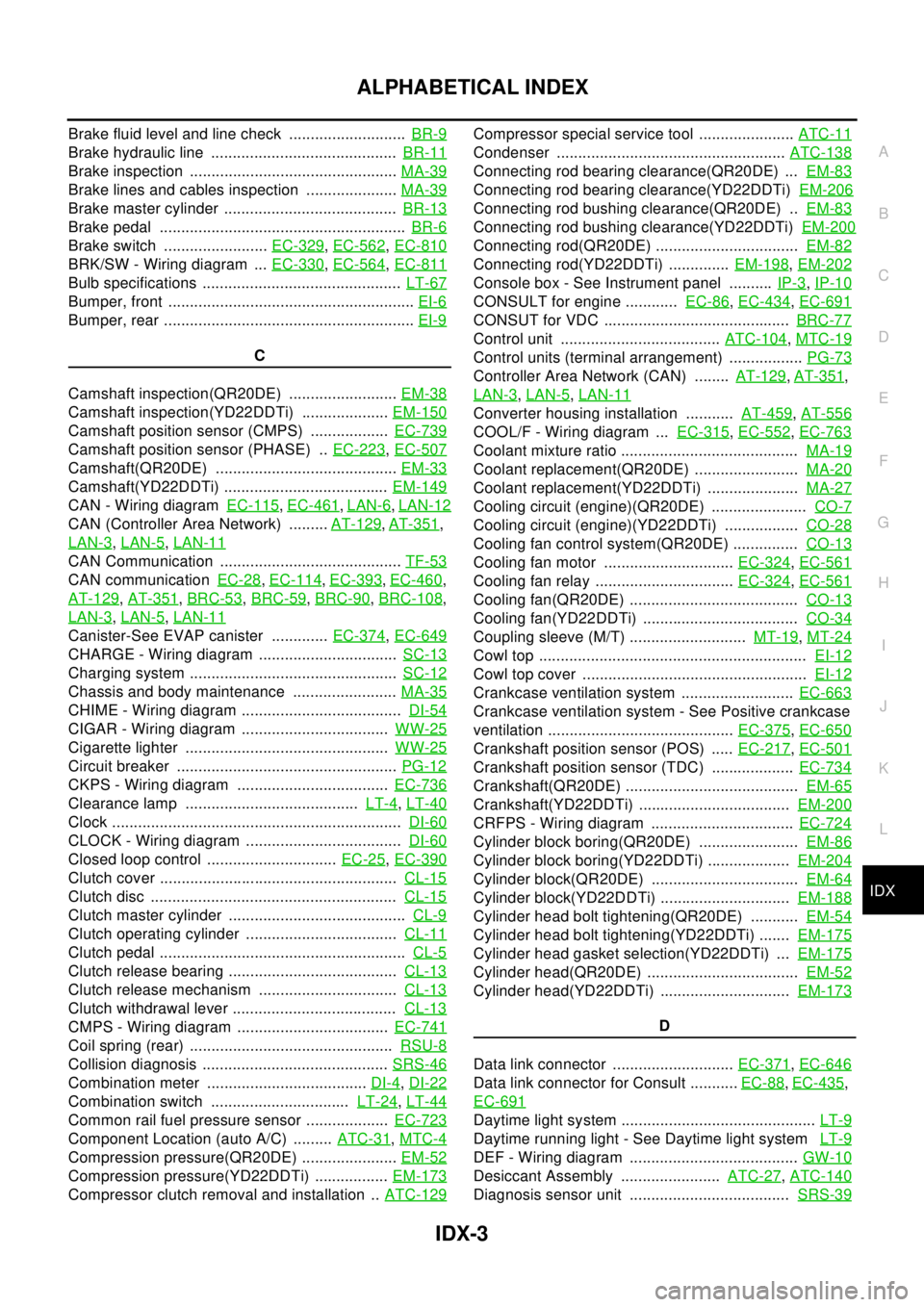
Brake fluid level and line check ...........................BR-9
Brake hydraulic line ...........................................BR-11
Brake inspection ................................................MA-39
Brake lines and cables inspection .....................MA-39
Brake master cylinder ........................................BR-13
Brake pedal .........................................................BR-6
Brake switch ........................EC-329,EC-562,EC-810
BRK/SW - Wiring diagram ...EC-330,EC-564,EC-811
Bulb specifications ..............................................LT-67
Bumper, front .........................................................EI-6
Bumper, rear ..........................................................EI-9
C
Camshaft inspection(QR20DE) .........................EM-38
Camshaft inspection(YD22DDTi) ....................EM-150
Camshaft position sensor (CMPS) ..................EC-739
Camshaft position sensor (PHASE) ..EC-223,EC-507
Camshaft(QR20DE) ..........................................EM-33
Camshaft(YD22DDTi) ......................................EM-149
CAN - Wiring diagramEC-115,EC-461,LAN-6,LAN-12
CAN (Controller Area Network) .........AT-129,AT-351,
LAN-3
,LAN-5,LAN-11
CAN Communication ..........................................TF-53
CAN communicationEC-28,EC-114,EC-393,EC-460,
AT-129
,AT-351,BRC-53,BRC-59,BRC-90,BRC-108,
LAN-3
,LAN-5,LAN-11
Canister-See EVAP canister .............EC-374,EC-649
CHARGE - Wiring diagram ................................SC-13
Charging system ................................................SC-12
Chassis and body maintenance ........................MA-35
CHIME - Wiring diagram .....................................DI-54
CIGAR - Wiring diagram ..................................WW-25
Cigarette lighter ...............................................WW-25
Circuit breaker ...................................................PG-12
CKPS - Wiring diagram ...................................EC-736
Clearance lamp ........................................LT-4,LT-40
Clock ...................................................................DI-60
CLOCK - Wiring diagram ....................................DI-60
Closed loop control ..............................EC-25,EC-390
Clutch cover .......................................................CL-15
Clutch disc .........................................................CL-15
Clutch master cylinder .........................................CL-9
Clutch operating cylinder ...................................CL-11
Clutch pedal .........................................................CL-5
Clutch release bearing .......................................CL-13
Clutch release mechanism ................................CL-13
Clutch withdrawal lever ......................................CL-13
CMPS - Wiring diagram ...................................EC-741
Coil spring (rear) ...............................................RSU-8
Collision diagnosis ...........................................SRS-46
Combination meter .....................................DI-4,DI-22
Combination switch ................................LT-24,LT-44
Common rail fuel pressure sensor ...................EC-723
Component Location (auto A/C) .........ATC-31,MTC-4
Compression pressure(QR20DE) ......................EM-52
Compression pressure(YD22DDTi) .................EM-173
Compressor clutch removal and installation ..ATC-129
Compressor special service tool ......................ATC-11
Condenser .....................................................ATC-138
Connecting rod bearing clearance(QR20DE) ...EM-83
Connecting rod bearing clearance(YD22DDTi)EM-206
Connecting rod bushing clearance(QR20DE) ..EM-83
Connecting rod bushing clearance(YD22DDTi)EM-200
Connecting rod(QR20DE) .................................EM-82
Connecting rod(YD22DDTi) ..............EM-198,EM-202
Console box - See Instrument panel ..........IP-3,IP-10
CONSULT for engine ............EC-86,EC-434,EC-691
CONSUT for VDC ...........................................BRC-77
Control unit .....................................ATC-104,MTC-19
Control units (terminal arrangement) .................PG-73
Controller Area Network (CAN) ........AT-129,AT-351,
LAN-3
,LAN-5,LAN-11
Converter housing installation ...........AT-459,AT-556
COOL/F - Wiring diagram ...EC-315,EC-552,EC-763
Coolant mixture ratio .........................................MA-19
Coolant replacement(QR20DE) ........................MA-20
Coolant replacement(YD22DDTi) .....................MA-27
Cooling circuit (engine)(QR20DE) ......................CO-7
Cooling circuit (engine)(YD22DDTi) .................CO-28
Cooling fan control system(QR20DE) ...............CO-13
Cooling fan motor ..............................EC-324,EC-561
Cooling fan relay ................................EC-324,EC-561
Cooling fan(QR20DE) .......................................CO-13
Cooling fan(YD22DDTi) ....................................CO-34
Coupling sleeve (M/T) ...........................MT-19,MT-24
Cowl top ..............................................................EI-12
Cowl top cover ....................................................EI-12
Crankcase ventilation system ..........................EC-663
Crankcase ventilation system - See Positive crankcase
ventilation ...........................................EC-375
,EC-650
Crankshaft position sensor (POS) .....EC-217,EC-501
Crankshaft position sensor (TDC) ...................EC-734
Crankshaft(QR20DE) ........................................EM-65
Crankshaft(YD22DDTi) ...................................EM-200
CRFPS - Wiring diagram .................................EC-724
Cylinder block boring(QR20DE) .......................EM-86
Cylinder block boring(YD22DDTi) ...................EM-204
Cylinder block(QR20DE) ..................................EM-64
Cylinder block(YD22DDTi) ..............................EM-188
Cylinder head bolt tightening(QR20DE) ...........EM-54
Cylinder head bolt tightening(YD22DDTi) .......EM-175
Cylinder head gasket selection(YD22DDTi) ...EM-175
Cylinder head(QR20DE) ...................................EM-52
Cylinder head(YD22DDTi) ..............................EM-173
D
Data link connector ............................EC-371
,EC-646
Data link connector for Consult ...........EC-88,EC-435,
EC-691
Daytime light system .............................................LT-9
Daytime running light - See Daytime light systemLT-9
DEF - Wiring diagram .......................................GW-10
Desiccant Assembly .......................ATC-27,ATC-140
Diagnosis sensor unit .....................................SRS-39