NISSAN X-TRAIL 2003 Electronic Repair Manual
Manufacturer: NISSAN, Model Year: 2003, Model line: X-TRAIL, Model: NISSAN X-TRAIL 2003Pages: 3066, PDF Size: 51.47 MB
Page 2361 of 3066
IDX-4
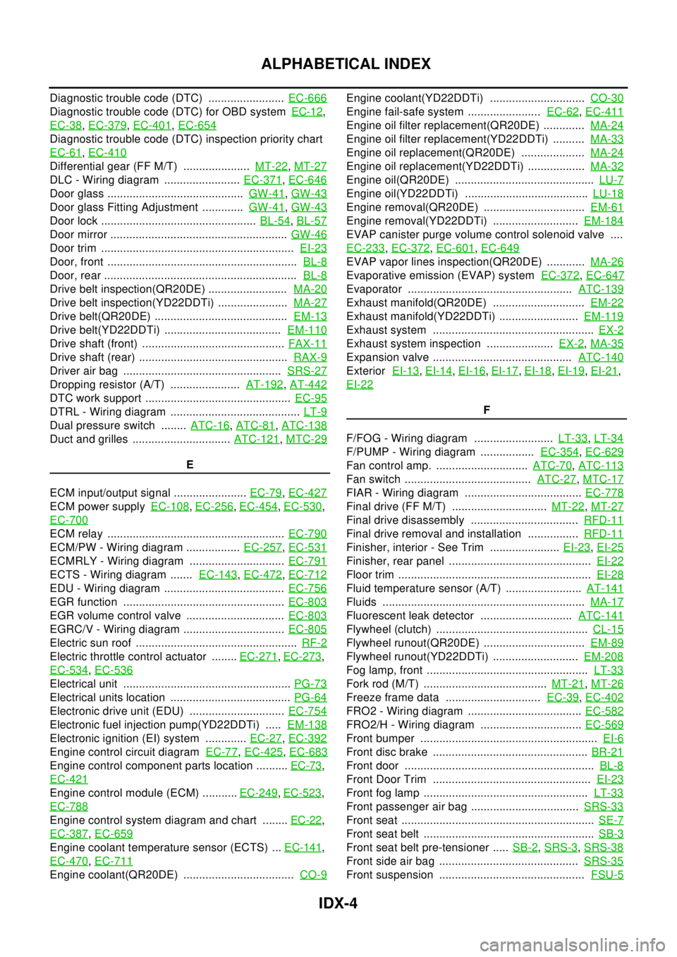
ALPHABETICAL INDEX
Diagnostic trouble code (DTC) ........................EC-666
Diagnostic trouble code (DTC) for OBD systemEC-12,
EC-38
,EC-379,EC-401,EC-654
Diagnostic trouble code (DTC) inspection priority chart
EC-61
,EC-410
Differential gear (FF M/T) .....................MT-22,MT-27
DLC - Wiring diagram ........................EC-371,EC-646
Door glass ...........................................GW-41,GW-43
Door glass Fitting Adjustment .............GW-41,GW-43
Door lock .................................................BL-54,BL-57
Door mirror ........................................................GW-46
Door trim .............................................................EI-23
Door, front ............................................................BL-8
Door, rear .............................................................BL-8
Drive belt inspection(QR20DE) .........................MA-20
Drive belt inspection(YD22DDTi) ......................MA-27
Drive belt(QR20DE) ..........................................EM-13
Drive belt(YD22DDTi) .....................................EM-110
Drive shaft (front) .............................................FAX-11
Drive shaft (rear) ...............................................RAX-9
Driver air bag ..................................................SRS-27
Dropping resistor (A/T) ......................AT-192,AT-442
DTC work support ..............................................EC-95
DTRL - Wiring diagram .........................................LT-9
Dual pressure switch ........ATC-16,ATC-81,ATC-138
Duct and grilles ...............................ATC-121,MTC-29
E
ECM input/output signal .......................EC-79
,EC-427
ECM power supplyEC-108,EC-256,EC-454,EC-530,
EC-700
ECM relay ........................................................EC-790
ECM/PW - Wiring diagram .................EC-257,EC-531
ECMRLY - Wiring diagram ..............................EC-791
ECTS - Wiring diagram .......EC-143,EC-472,EC-712
EDU - Wiring diagram ......................................EC-756
EGR function ...................................................EC-803
EGR volume control valve ...............................EC-803
EGRC/V - Wiring diagram ................................EC-805
Electric sun roof ...................................................RF-2
Electric throttle control actuator ........EC-271,EC-273,
EC-534
,EC-536
Electrical unit .....................................................PG-73
Electrical units location ......................................PG-64
Electronic drive unit (EDU) ..............................EC-754
Electronic fuel injection pump(YD22DDTi) .....EM-138
Electronic ignition (EI) system .............EC-27,EC-392
Engine control circuit diagramEC-77,EC-425,EC-683
Engine control component parts location ..........EC-73,
EC-421
Engine control module (ECM) ...........EC-249,EC-523,
EC-788
Engine control system diagram and chart ........EC-22,
EC-387
,EC-659
Engine coolant temperature sensor (ECTS) ...EC-141,
EC-470
,EC-711
Engine coolant(QR20DE) ...................................CO-9
Engine coolant(YD22DDTi) ..............................CO-30
Engine fail-safe system .......................EC-62,EC-411
Engine oil filter replacement(QR20DE) .............MA-24
Engine oil filter replacement(YD22DDTi) ..........MA-33
Engine oil replacement(QR20DE) ....................MA-24
Engine oil replacement(YD22DDTi) ..................MA-32
Engine oil(QR20DE) ............................................LU-7
Engine oil(YD22DDTi) .......................................LU-18
Engine removal(QR20DE) ................................EM-61
Engine removal(YD22DDTi) ...........................EM-184
EVAP canister purge volume control solenoid valve ....
EC-233
,EC-372,EC-601,EC-649
EVAP vapor lines inspection(QR20DE) ............MA-26
Evaporative emission (EVAP) systemEC-372,EC-647
Evaporator ....................................................ATC-139
Exhaust manifold(QR20DE) .............................EM-22
Exhaust manifold(YD22DDTi) .........................EM-119
Exhaust system ...................................................EX-2
Exhaust system inspection .....................EX-2,MA-35
Expansion valve ............................................ATC-140
ExteriorEI-13,EI-14,EI-16,EI-17,EI-18,EI-19,EI-21,
EI-22
F
F/FOG - Wiring diagram .........................LT-33
,LT-34
F/PUMP - Wiring diagram .................EC-354,EC-629
Fan control amp. .............................ATC-70,ATC-113
Fan switch ........................................ATC-27,MTC-17
FIAR - Wiring diagram .....................................EC-778
Final drive (FF M/T) ..............................MT-22,MT-27
Final drive disassembly ..................................RFD-11
Final drive removal and installation ................RFD-11
Finisher, interior - See Trim ......................EI-23,EI-25
Finisher, rear panel .............................................EI-22
Floor trim .............................................................EI-28
Fluid temperature sensor (A/T) ........................AT-141
Fluids ................................................................MA-17
Fluorescent leak detector .............................ATC-141
Flywheel (clutch) ................................................CL-15
Flywheel runout(QR20DE) ................................EM-89
Flywheel runout(YD22DDTi) ...........................EM-208
Fog lamp, front ...................................................LT-33
Fork rod (M/T) .......................................MT-21,MT-26
Freeze frame data ..............................EC-39,EC-402
FRO2 - Wiring diagram ....................................EC-582
FRO2/H - Wiring diagram ................................EC-569
Front bumper ........................................................EI-6
Front disc brake .................................................BR-21
Front door ............................................................BL-8
Front Door Trim ..................................................EI-23
Front fog lamp ....................................................LT-33
Front passenger air bag ..................................SRS-33
Front seat .............................................................SE-7
Front seat belt ......................................................SB-3
Front seat belt pre-tensioner .....SB-2,SRS-3,SRS-38
Front side air bag ............................................SRS-35
Front suspension ..............................................FSU-5
Page 2362 of 3066
IDX-5
A
C
D
E
F
G
H
I
J
K
L B
IDX
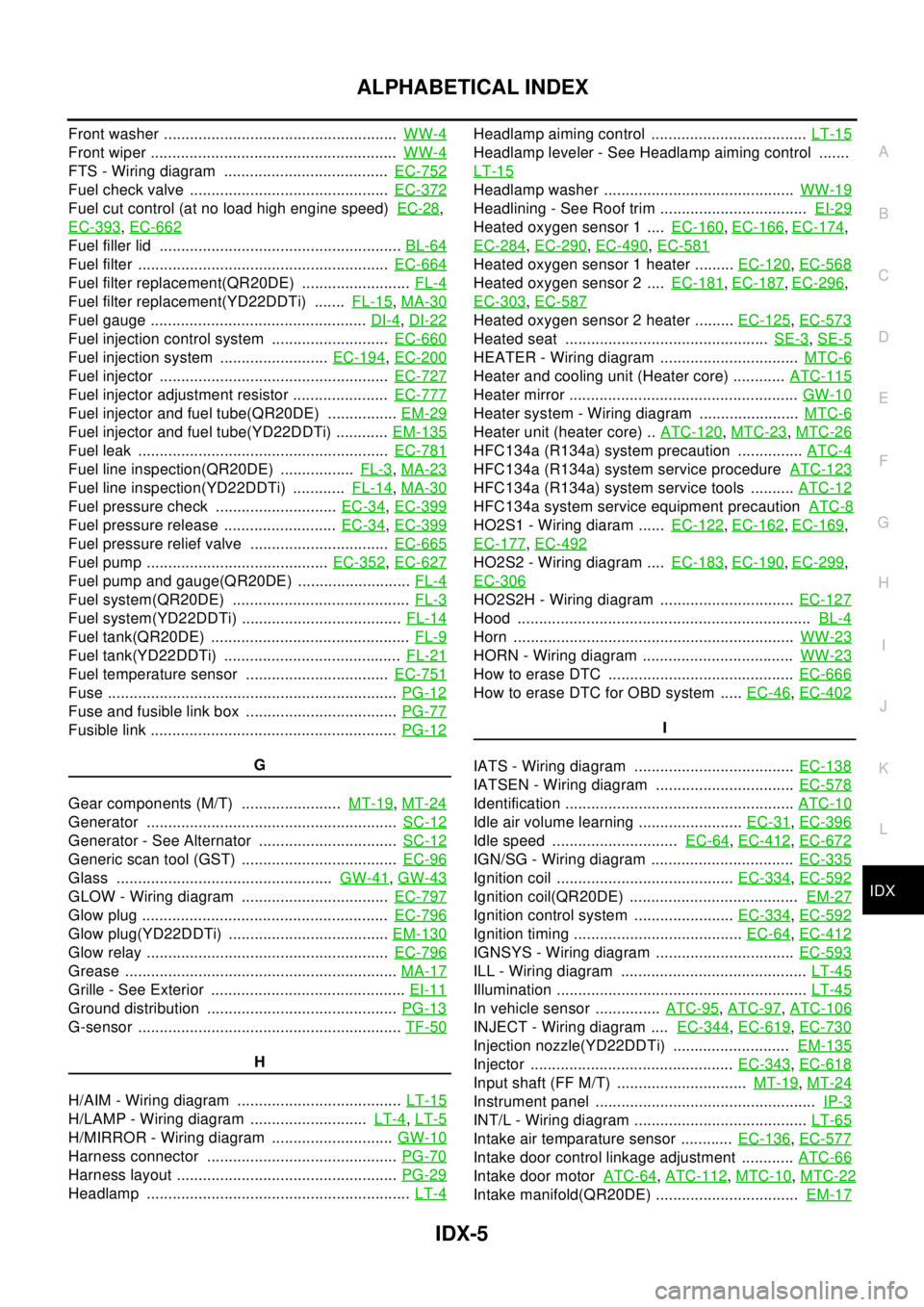
ALPHABETICAL INDEX
Front washer ......................................................WW-4
Front wiper .........................................................WW-4
FTS - Wiring diagram ......................................EC-752
Fuel check valve ..............................................EC-372
Fuel cut control (at no load high engine speed)EC-28,
EC-393
,EC-662
Fuel filler lid ........................................................BL-64
Fuel filter ..........................................................EC-664
Fuel filter replacement(QR20DE) .........................FL-4
Fuel filter replacement(YD22DDTi) .......FL-15,MA-30
Fuel gauge ..................................................DI-4,DI-22
Fuel injection control system ...........................EC-660
Fuel injection system .........................EC-194,EC-200
Fuel injector .....................................................EC-727
Fuel injector adjustment resistor ......................EC-777
Fuel injector and fuel tube(QR20DE) ................EM-29
Fuel injector and fuel tube(YD22DDTi) ............EM-135
Fuel leak ..........................................................EC-781
Fuel line inspection(QR20DE) .................FL-3,MA-23
Fuel line inspection(YD22DDTi) ............FL-14,MA-30
Fuel pressure check ............................EC-34,EC-399
Fuel pressure release ..........................EC-34,EC-399
Fuel pressure relief valve ................................EC-665
Fuel pump ..........................................EC-352,EC-627
Fuel pump and gauge(QR20DE) ..........................FL-4
Fuel system(QR20DE) .........................................FL-3
Fuel system(YD22DDTi) .....................................FL-14
Fuel tank(QR20DE) ..............................................FL-9
Fuel tank(YD22DDTi) .........................................FL-21
Fuel temperature sensor .................................EC-751
Fuse ...................................................................PG-12
Fuse and fusible link box ...................................PG-77
Fusible link .........................................................PG-12
G
Gear components (M/T) .......................MT-19
,MT-24
Generator ..........................................................SC-12
Generator - See Alternator ................................SC-12
Generic scan tool (GST) ....................................EC-96
Glass ..................................................GW-41,GW-43
GLOW - Wiring diagram ..................................EC-797
Glow plug .........................................................EC-796
Glow plug(YD22DDTi) .....................................EM-130
Glow relay ........................................................EC-796
Grease ...............................................................MA-17
Grille - See Exterior .............................................EI-11
Ground distribution ............................................PG-13
G-sensor .............................................................TF-50
H
H/AIM - Wiring diagram ......................................LT-15
H/LAMP - Wiring diagram ...........................LT-4,LT-5
H/MIRROR - Wiring diagram ............................GW-10
Harness connector ............................................PG-70
Harness layout ...................................................PG-29
Headlamp .............................................................LT-4
Headlamp aiming control ....................................LT-15
Headlamp leveler - See Headlamp aiming control .......
LT-15
Headlamp washer ............................................WW-19
Headlining - See Roof trim ..................................EI-29
Heated oxygen sensor 1 ....EC-160,EC-166,EC-174,
EC-284
,EC-290,EC-490,EC-581
Heated oxygen sensor 1 heater .........EC-120,EC-568
Heated oxygen sensor 2 ....EC-181,EC-187,EC-296,
EC-303
,EC-587
Heated oxygen sensor 2 heater .........EC-125,EC-573
Heated seat ...............................................SE-3,SE-5
HEATER - Wiring diagram ................................MTC-6
Heater and cooling unit (Heater core) ............ATC-115
Heater mirror .....................................................GW-10
Heater system - Wiring diagram .......................MTC-6
Heater unit (heater core) ..ATC-120,MTC-23,MTC-26
HFC134a (R134a) system precaution ...............ATC-4
HFC134a (R134a) system service procedureATC-123
HFC134a (R134a) system service tools ..........ATC-12
HFC134a system service equipment precautionATC-8
HO2S1 - Wiring diaram ......EC-122,EC-162,EC-169,
EC-177
,EC-492
HO2S2 - Wiring diagram ....EC-183,EC-190,EC-299,
EC-306
HO2S2H - Wiring diagram ...............................EC-127
Hood ....................................................................BL-4
Horn .................................................................WW-23
HORN - Wiring diagram ...................................WW-23
How to erase DTC ...........................................EC-666
HowtoeraseDTCforOBDsystem .....EC-46,EC-402
I
IATS - Wiring diagram .....................................EC-138
IATSEN - Wiring diagram ................................EC-578
Identification .....................................................ATC-10
Idle air volume learning ........................EC-31,EC-396
Idle speed .............................EC-64,EC-412,EC-672
IGN/SG - Wiring diagram .................................EC-335
Ignition coil .........................................EC-334,EC-592
Ignition coil(QR20DE) .......................................EM-27
Ignition control system .......................EC-334,EC-592
Ignition timing .......................................EC-64,EC-412
IGNSYS - Wiring diagram ................................EC-593
ILL - Wiring diagram ...........................................LT-45
Illumination ..........................................................LT-45
In vehicle sensor ...............ATC-95,ATC-97,ATC-106
INJECT - Wiring diagram ....EC-344,EC-619,EC-730
Injection nozzle(YD22DDTi) ...........................EM-135
Injector ...............................................EC-343,EC-618
Input shaft (FF M/T) ..............................MT-19,MT-24
Instrument panel ...................................................IP-3
INT/L - Wiring diagram ........................................LT-65
Intake air temparature sensor ............EC-136,EC-577
Intake door control linkage adjustment ............ATC-66
Intake door motorATC-64,ATC-112,MTC-10,MTC-22
Intake manifold(QR20DE) .................................EM-17
Page 2363 of 3066
IDX-6
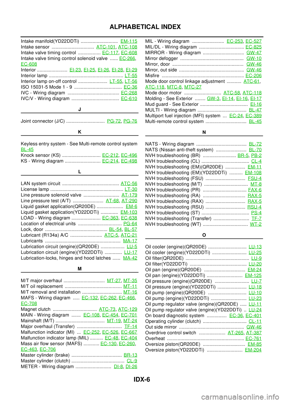
ALPHABETICAL INDEX
Intake manifold(YD22DDTi) ............................EM-115
Intake sensor ................................ATC-101,ATC-108
Intake valve timing control .................EC-117,EC-608
Intake valve timing control solenoid valve ......EC-266,
EC-608
Interior .......................EI-23,EI-25,EI-26,EI-28,EI-29
Interior lamp ........................................................LT-55
Interior lamp on-off control ......................LT-55,LT-56
ISO 15031-5 Mode 1 - 9 ....................................EC-36
IVC - Wiring diagram .......................................EC-268
IVC/V - Wiring diagram ....................................EC-610
J
Joint connector (J/C) .............................PG-72
,PG-76
K
Keyless entry system - See Multi-remote control system
BL-45
Knock sensor (KS) .............................EC-212,EC-496
KS - Wiring diagram ...........................EC-214,EC-498
L
LAN system circuit ...........................................ATC-56
License lamp .......................................................LT-30
Line pressure solenoid valve ...........................AT-179
Line pressure test (A/T) .......................AT-68,AT-290
Liquid gasket application(QR20DE) ....................EM-6
Liquid gasket application(YD22DDTi) .............EM-103
LOAD - Wiring diagram ......................EC-363,EC-638
Location of electrical units .................................PG-64
Lock, door ...............................................BL-54,BL-57
Lubricant (R134a) A/C ........................ATC-5,ATC-21
Lubricants .........................................................MA-17
Lubrication circuit (engine)(QR20DE) ..................LU-5
Lubrication circuit (engine)(YD22DDTi) .............LU-17
Lubrication-locks, hinges and hood latches ......MA-42
M
M/T major overhaul ...............................MT-27
,MT-35
M/T oil replacement ...........................................MT-11
M/T removal and installation ..............................MT-16
MAFS - Wiring diagram .....EC-132,EC-262,EC-466,
EC-708
Magnet clutch .................................ATC-73,ATC-129
MAIN - Wiring diagram .......EC-108,EC-454,EC-701
Mainshaft (M/T) .....................................MT-19,MT-24
Major overhaul (Transfer) ..................................TF-14
Malfunction indicator (MI) ...EC-252,EC-526,EC-667
Malfunction indicator lamp (MIL) ..........EC-48,EC-404
Mass air flow sensor (MAFS) ............EC-130,EC-260,
EC-463
,EC-706
Master cylinder (brake) ......................................BR-13
Master cylinder (clutch) ........................................CL-9
METER - Wiring diagram ...........................DI-8,DI-26
MIL - Wiring diagram ........................EC-253,EC-527
MIL/DL - Wiring diagram ..................................EC-825
MIRROR - Wiring diagram ...............................GW-47
Mirror defogger ................................................GW-10
Mirror, door ......................................................GW-46
Mirror, out side .................................................GW-46
Misfire ..............................................................EC-206
Mode door control linkage adjustment ...........ATC-61,
ATC-118
,MTC-8,MTC-27
Mode door motor ............................ATC-58,ATC-118
Molding - See Exterior ........GW-3,EI-14,EI-16,EI-17
Mud guard - See Exterior ....................................EI-16
MULTI - Wiring diagram .....................................BL-47
Multiport fuel injection (MFI) system ...EC-24,EC-389
Multi-remote control system ...............................BL-45
N
NATS - Wiring diagram ......................................BL-72
NATS (Nissan anti-theft system) .......................BL-70
NVH troubleshooting (BR) .........................BR-5,PB-2
NVH troubleshooting (CL) ....................................CL-4
NVH troubleshooting (EM)(QR20DE) ...............EM-11
NVH troubleshooting (EM)(YD22DDTi) ..........EM-108
NVH troubleshooting (FSU) ..............................FSU-4
NVH troubleshooting (M/T) .................................MT-8
NVH troubleshooting (PR) .................................FAX-6
NVH troubleshooting (RA) ................................RAX-5
NVH troubleshooting (RAX) ..............................RAX-5
NVH troubleshooting (RSU) ..............................RSU-4
NVH troubleshooting (ST) ....................................PS-4
NVH troubleshooting (Transfer) ...........................TF-7
NVH troubleshooting (WT) ..................................WT-2
O
Oil cooler (engine)(QR20DE) .............................LU-13
Oil cooler (engine)(YD22DDTi) ..........................LU-25
Oil filter(QR20DE) ................................................LU-9
Oil filter(YD22DDTi) ...........................................LU-20
Oil pan (engine)(QR20DE) ...............................EM-24
Oil pan (engine)(YD22DDTi) ...........................EM-125
Oil pressure (engine)(QR20DE) ..........................LU-7
Oil pressure (engine)(YD22DDTi) ......................LU-18
Oil pump (engine)(QR20DE) .............................LU-10
Oil pump (engine)(YD22DDTi) ...........................LU-23
Oil pump regulator valve (engine)(QR20DE) .....LU-11
Oil pump regulator valve (engine)(YD22DDTi) ..LU-24
On board diagnostic system ...............EC-36,EC-401
Operating cylinder (clutch) .................................CL-11
Out side mirror .................................................GW-46
Overdrive control switch ....................AT-265,AT-387
Overheat ..........................................................EC-761
Oversize piston(QR20DE) ................................EM-85
Oversize piston(YD22DDTi) ...........................EM-204
Page 2364 of 3066
IDX-7
A
C
D
E
F
G
H
I
J
K
L B
IDX
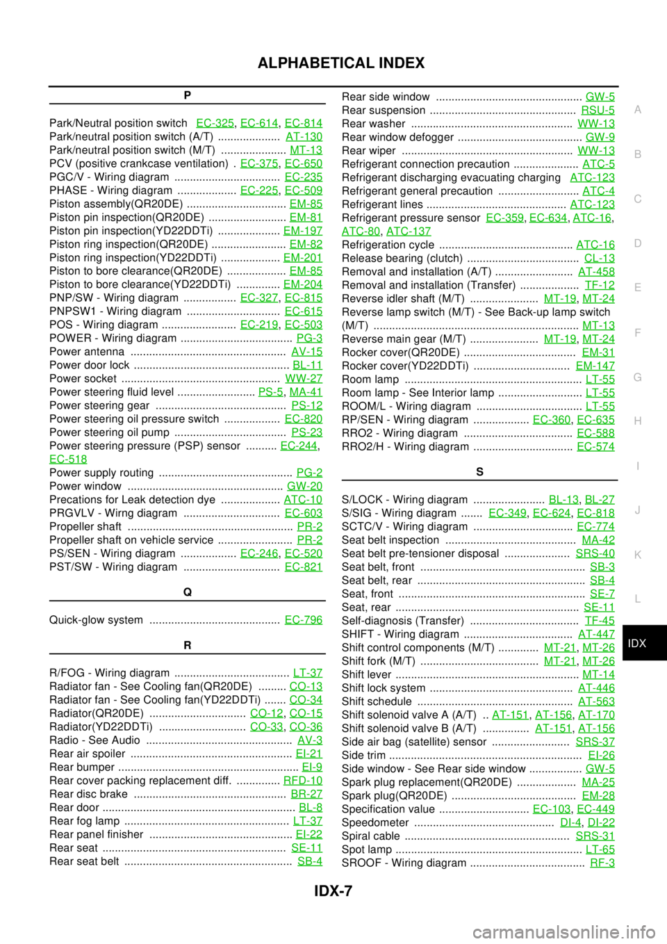
ALPHABETICAL INDEX
P
Park/Neutral position switchEC-325
,EC-614,EC-814
Park/neutral position switch (A/T) ....................AT-130
Park/neutral position switch (M/T) .....................MT-13
PCV (positive crankcase ventilation) .EC-375,EC-650
PGC/V - Wiring diagram ..................................EC-235
PHASE - Wiring diagram ...................EC-225,EC-509
Piston assembly(QR20DE) ................................EM-85
Piston pin inspection(QR20DE) .........................EM-81
Piston pin inspection(YD22DDTi) ....................EM-197
Piston ring inspection(QR20DE) ........................EM-82
Piston ring inspection(YD22DDTi) ...................EM-201
Piston to bore clearance(QR20DE) ...................EM-85
Piston to bore clearance(YD22DDTi) ..............EM-204
PNP/SW - Wiring diagram .................EC-327,EC-815
PNPSW1 - Wiring diagram ..............................EC-615
POS - Wiring diagram ........................EC-219,EC-503
POWER - Wiring diagram ....................................PG-3
Power antenna ..................................................AV-15
Power door lock ..................................................BL-11
Power socket ...................................................WW-27
Power steering fluid level .........................PS-5,MA-41
Power steering gear ..........................................PS-12
Power steering oil pressure switch ..................EC-820
Power steering oil pump ....................................PS-23
Power steering pressure (PSP) sensor ..........EC-244,
EC-518
Power supply routing ...........................................PG-2
Power window ..................................................GW-20
Precations for Leak detection dye ...................ATC-10
PRGVLV - Wirng diagram ...............................EC-603
Propeller shaft .....................................................PR-2
Propeller shaft on vehicle service ........................PR-2
PS/SEN - Wiring diagram ..................EC-246,EC-520
PST/SW - Wiring diagram ...............................EC-821
Q
Quick-glow system ..........................................EC-796
R
R/FOG - Wiring diagram .....................................LT-37
Radiator fan - See Cooling fan(QR20DE) .........CO-13
Radiator fan - See Cooling fan(YD22DDTi) .......CO-34
Radiator(QR20DE) ...............................CO-12,CO-15
Radiator(YD22DDTi) ............................CO-33,CO-36
Radio - See Audio ...............................................AV-3
Rear air spoiler ....................................................EI-21
Rear bumper ..........................................................EI-9
Rear cover packing replacement diff. ..............RFD-10
Rear disc brake .................................................BR-27
Rear door ..............................................................BL-8
Rear fog lamp .....................................................LT-37
Rear panel finisher ..............................................EI-22
Rear seat ...........................................................SE-11
Rear seat belt ......................................................SB-4
Rear side window ...............................................GW-5
Rear suspension ...............................................RSU-5
Rear washer ....................................................WW-13
Rear window defogger ........................................GW-9
Rear wiper .......................................................WW-13
Refrigerant connection precaution .....................ATC-5
Refrigerant discharging evacuating chargingATC-123
Refrigerant general precaution ..........................ATC-4
Refrigerant lines .............................................ATC-123
Refrigerant pressure sensorEC-359,EC-634,ATC-16,
ATC-80
,ATC-137
Refrigeration cycle ...........................................ATC-16
Release bearing (clutch) ....................................CL-13
Removal and installation (A/T) .........................AT-458
Removal and installation (Transfer) ...................TF-12
Reverse idler shaft (M/T) ......................MT-19,MT-24
Reverselampswitch(M/T)-SeeBack-uplampswitch
(M/T) ..................................................................MT-13
Reverse main gear (M/T) ......................MT-19,MT-24
Rocker cover(QR20DE) ....................................EM-31
Rocker cover(YD22DDTi) ...............................EM-147
Room lamp .........................................................LT-55
Room lamp - See Interior lamp ...........................LT-55
ROOM/L - Wiring diagram ..................................LT-55
RP/SEN - Wiring diagram ..................EC-360,EC-635
RRO2 - Wiring diagram ...................................EC-588
RRO2/H - Wiring diagram ................................EC-574
S
S/LOCK - Wiring diagram .......................BL-13
,BL-27
S/SIG - Wiring diagram .......EC-349,EC-624,EC-818
SCTC/V - Wiring diagram ................................EC-774
Seat belt inspection ..........................................MA-42
Seat belt pre-tensioner disposal .....................SRS-40
Seat belt, front .....................................................SB-3
Seat belt, rear ......................................................SB-4
Seat, front ............................................................SE-7
Seat, rear ...........................................................SE-11
Self-diagnosis (Transfer) ...................................TF-45
SHIFT - Wiring diagram ...................................AT-447
Shift control components (M/T) .............MT-21,MT-26
Shift fork (M/T) ......................................MT-21,MT-26
Shift lever ...........................................................MT-14
Shift lock system ..............................................AT-446
Shift schedule ..................................................AT-563
Shift solenoid valve A (A/T) ..AT-151,AT-156,AT-170
Shift solenoid valve B (A/T) ...............AT-151,AT-156
Side air bag (satellite) sensor .........................SRS-37
Side trim ..............................................................EI-26
Side window - See Rear side window .................GW-5
Spark plug replacement(QR20DE) ...................MA-25
Spark plug(QR20DE) ........................................EM-28
Specification value .............................EC-103,EC-449
Speedometer .............................................DI-4,DI-22
Spiral cable .....................................................SRS-31
Spot lamp ............................................................LT-65
SROOF - Wiring diagram .....................................RF-3
Page 2365 of 3066
IDX-8
ALPHABETICAL INDEX
SRS - See Supplemental Restraint System .....SRS-5
SRS - Wiring diagram/LHD .............................SRS-10
SRS - Wiring diagram/RHD ............................SRS-12
SRS Trouble diagnoses ....................................SRS-7
Stall test (A/T) ......................................AT-65,AT-287
Standardized relay .............................................PG-74
START - Wiring diagram ........................SC-22,SC-23
Start signal ..........................EC-348,EC-623,EC-818
Starter ................................................................SC-21
Starting system ..................................................SC-21
Steering gear and linkage inspection ................MA-40
Steering knuckle ................................................FAX-7
Steering linkage .................................................PS-12
Steering wheel and column .......................PS-6,PS-9
Stop lamp ................................................LT-26,LT-42
Stop lamp switch ................................EC-329,EC-562
STOP/L - Wiring diagram ........................LT-26,LT-42
Strut (rear) ........................................................RSU-8
Suction control valve ........................................EC-772
Sunload sensor ...............ATC-98,ATC-100,ATC-107
Sunroof ................................................................RF-2
Super lock ..........................................................BL-24
Supplemental Restraint System .......................SRS-5
Supplemental restraint system - Wiring diagram/LHD ..
SRS-10
Supplemental restraint system - Wiring diagram/RHD .
SRS-12
Suspension .......................................................MA-41
Symbols and abbreviations .................................GI-22
Symptom matrix chart ...........EC-69,EC-417,EC-676
Synchronizer (M/T) ...............................MT-19,MT-24
System readiness test (SRT) code ....................EC-40
T
T/MTR - Wiring diagram ....................EC-275
,EC-538
Tachometer ................................................DI-4,DI-22
Tail lamp .................................................LT-30,LT-40
TAIL/L - Wiring diagram ......................................LT-30
Tailgate lamp ......................................................LT-30
TCM circuit diagram ...........................................AT-16
TCM inspection table .........................AT-126,AT-348
THEFT - Wiring diagram ....................................BL-65
Theft warning system .........................................BL-65
Thermal protector ............................................ATC-81
Thermostat(QR20DE) .......................................CO-21
Thermostat(YD22DDTi) ....................................CO-43
Three way catalyst function .............................EC-229
Three way catalyst(QR20DE) ...........................EM-22
Throttle control motor relay ................EC-279,EC-542
Throttle position sensor (TPS) ...........EC-146,EC-475
Throttle position switch ......................AT-266,AT-388
Time control system ..........................................BCS-3
Timing chain(QR20DE) .....................................EM-43
Timing chain(YD22DDTi) ..................EM-158,EM-163
TM/RLY - Wiring diagram ..................EC-281,EC-544
Torque converter installation .............AT-459,AT-556
TPS - Wiring diagram ........................EC-149,EC-479
Transfer case .....................................................TF-23
Transfer control unit inspection table ......TF-42,TF-49
Transmission case (M/T) ......................MT-18,MT-23
Trouble diagnoses ..............................................GI-10
Turbocharger charge air cooler(YD22DDTi) ...EM-114
Turbocharger(YD22DDTi) ...............................EM-119
TURN - Wiring diagram ..........................LT-17,LT-19
Turn signal lamp .....................................LT-17,LT-42
Two trip detection logic .......................EC-36,EC-401
V
Vacuum hose (brake system) ............................BR-19
Vacuum hose drawing (Engine control)EC-23,EC-388
Vacuum pump(YD22DDTi) .............................EM-131
Valve clearance(QR20DE) ...............................EM-40
Valve clearance(YD22DDTi) ...........................EM-154
Valve guide(QR20DE) ......................................EM-57
Valve guide(YD22DDTi) .................................EM-180
Valve lifter(QR20DE) ........................................EM-33
Valve lifter(YD22DDTi) ...................................EM-152
Valve seat(QR20DE) ........................................EM-58
Valve seat(YD22DDTi) ...................................EM-181
Valve spring(QR20DE) .....................................EM-60
Valve spring(YD22DDTi) ................................EM-183
VDC -Wiring diagram ......................................BRC-65
Vehicle speed sensor (VSS)EC-239,EC-513,EC-744
Ventilation air filter ........................................ATC-114
Viscosity number (SAE) ....................................MA-18
VSS - Wiring diagram .........EC-241,EC-515,EC-745
W
Warning chime ....................................................DI-52
Warning lamps ....................................................DI-39
Washer, front .....................................................WW-4
Washer, rear ....................................................WW-13
Water control valve(QR20DE) ..........................CO-21
Water pump(QR20DE) .....................................CO-19
Water pump(YD22DDTi) ...................................CO-40
Water temperature gauge ..........................DI-4,DI-22
Weatherstrip - See Exterior ...............................BL-10
Wheel alignment (front) ....................................FSU-6
Wheel alignment (rear) .....................................RSU-6
Wheel balance ..................................................MA-38
Wheel bearing (front axle) .................................FAX-7
Wheel bearing (rear) .........................................RAX-6
Wheel hub (front) ...............................................FAX-7
Wheel hub (rear) ...............................................RAX-6
Wheel sensor(VDC) ......................................BRC-119
Wheel sensors (ABS) .....................................BRC-48
WINDOW - Wiring diagram ..............................GW-24
Window, back ....................................................GW-7
Window, back door ............................................GW-7
Window, door ......................................GW-41,GW-43
Window, rear side ..............................................GW-5
Window, side - See Rear side window ..............GW-5
Windshield .........................................................GW-3
Page 2366 of 3066
IDX-9
A
C
D
E
F
G
H
I
J
K
L B
IDX
ALPHABETICAL INDEX
WIP/R - Wiring diagram ...................................WW-13
WIPER - Wiring diagram ...................................WW-6
Wiper and washer ..............................................WW-4
Wiper, front ........................................................WW-4
Wiper, rear .......................................................WW-13
Wiring diagram - AT - LAN .................AT-214,AT-444
Wiring Diagram (Cell code) list ..........................PG-61
Wiring diagram (Transfer) ...................................TF-36
Withdrawal lever (clutch) ...................................CL-13
Page 2367 of 3066
IP-1
INSTRUMENT PANEL
IBODY
CONTENTS
C
D
E
F
G
H
J
K
L
M
SECTION
A
B
IP
INSTRUMENT PANEL
PRECAUTIONS .......................................................... 2
Precautions for Supplemental Restraint System
(SRS) “AIR BAG” and “SEAT BELT PRE-TEN-
SIONER” .................................................................. 2
Precautions .............................................................. 2
INSTRUMENT PANEL ASSEMBLY ........................... 3
Component Parts Drawing ....................................... 3
Removal and Installation .......................................... 5
TABLE OF WORK ITEM ....................................... 5
FRONT SPEAKER GRILLE .................................. 6
INSTRUMENT FINISHER ..................................... 6
CUP HOLDER ....................................................... 6
CLUSTER LID A ................................................... 6
COMBINATION METER ....................................... 6
GPS ANTENNA .................................................... 6
POCKET ............................................................... 6
STEERING COLUMN COVER ............................. 6
INSTRUMENT LOWER DRIVER PANEL ............. 7
MIRROR CONTROL SWITCH .............................. 7CLUSTER LID C ................................................... 7
AUDIO UNIT AND POCKET ................................. 7
CLUSTER LID FINISHER ..................................... 7
A/T OR M/T FINISHER ......................................... 8
CENTER CONSOLE ............................................. 8
CD AUTO–CHANGER AND POCKET .................. 8
HEATER CONTROL FINISHER ............................ 8
HEATER CONTROLLER ....................................... 8
LOWER INSTRUMENT COVER ........................... 8
INSTRUMENT LOWER CENTER PANEL ............ 8
GLOVE BOX ......................................................... 9
LOWER INSTRUMENT PANEL ............................ 9
GLOVE BOX COVER ............................................ 9
FRONT PASSENGER AIR BAG MODULE ........... 9
INSTRUMENT MASK ............................................ 9
FRONT PILLAR GARNISH ................................... 9
INSTRUMENT PANEL .......................................... 9
Disassembly and Assembly .................................... 10
CONSOLE BOX ASSEMBLY .............................. 10
Page 2368 of 3066
IP-2
PRECAUTIONS
PRECAUTIONS
PFP:00001
Precautions for Supplemental Restraint System (SRS) “AIR BAG” and “SEAT
BELT PRE-TENSIONER”
EIS001NY
The Supplemental Restraint System such as “AIR BAG” and “SEAT BELT PRE-TENSIONER”, used along
with a front seat belt, helps to reduce the risk or severity of injury to the driver and front passenger for certain
types of collision. Information necessary to service the system safely is included in the SRS and SB section of
this Service Manual.
WAR NIN G:
lTo avoid rendering the SRS inoperative, which could increase the risk of personal injury or death
in the event of a collision which would result in air bag inflation, all maintenance must be per-
formed by an authorized NISSAN/INFINITI dealer.
lImproper maintenance, including incorrect removal and installation of the SRS, can lead to per-
sonal injury caused by unintentional activation of the system. For removal of Spiral Cable and Air
Bag Module, see the SRS section.
lDo not use electrical test equipment on any circuit related to the SRS unless instructed to in this
Service Manual. SRS wiring harnesses can be identified by yellow harness connector.
PrecautionsEIS001NZ
lDisconnect both battery cables in advance.
lDisconnect air bag system line in advance.
lNever tamper with or force air bag lid open, as this may adversely affect air bag performance.
lBe careful not to scratch pad and other parts.
lWhen removing or disassembling any part, be careful not to damage or deform it. Protect parts, which
may get in the way with cloth.
lWhen removing parts with a screwdriver or other tool, protect parts by wrapping them with vinyl or tape.
lKeep removed parts protected with cloth.
lIf a clip is deformed or damaged, replace it.
lIf an unreusable part is removed, replace it with a new one.
lTighten bolts and nuts firmly to the specified torque.
lAfter re-assembly has been completed, make sure each part functions correctly.
lRemove stains in the following way.
Water-soluble stains:
Dip a soft cloth in warm water, and then squeeze it tightly. After wiping the stain, wipe with a soft dry cloth.
Oil stain:
Dissolve a synthetic detergent in warm water (density of 2 to 3% or less), dip the cloth, then clean off the stain
with the cloth. Next, dip the cloth in fresh water and squeeze it tightly. Then clean off the detergent completely.
Then wipe the area with a soft dry cloth.
lDo not use any organic solvent, such as thinner or benzine.
Page 2369 of 3066
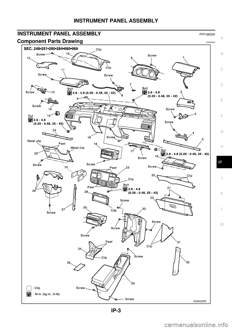
INSTRUMENT PANEL ASSEMBLY
IP-3
C
D
E
F
G
H
J
K
L
MA
B
IP
INSTRUMENT PANEL ASSEMBLYPFP:68200
Component Parts DrawingEIS000NH
SIIA0225E
Page 2370 of 3066

IP-4
INSTRUMENT PANEL ASSEMBLY
1 Front passenger air bag module 2 Front speaker grille (left) 3 Front side speaker (left)
4 Cup holder (left) 5 Instrument finisher B 6 Combination meter
7 Instrument mask (left) 8 GPS antenna 9 Instrument mask (right)
10 Instrument cluster lid A 11 Pocket 12 Front speaker grille (right)
13 Front side speaker (right) 14 Cup holder (right) 15 Mirror control switch
16 Instrument panel & pad 17 Instrument reinforcement 18 Audio unit and pocket
19 Glove box cover 20 Lower instrument panel 21 Glove box pin
22 Glove box 23 Cluster lid C 24 Instrument finisher A
25 Instrument lower driver panel 26 Column cover, key cylinder escutcheon 27 Cluster lid finisher (right)
28 Heater control finisher 29 CD auto–changer and pocket 30 instrument lower center panel
31 Lower instrument cover 32 Cluster lid finisher (left) 33 Center console
34 A/T or M/T finisher 35 Console mask 36 Seal case (inner case)