NISSAN X-TRAIL 2003 Electronic Repair Manual
X-TRAIL 2003
NISSAN
NISSAN
https://www.carmanualsonline.info/img/5/57402/w960_57402-0.png
NISSAN X-TRAIL 2003 Electronic Repair Manual
Trending: key battery, air suspension, spare tire location, brake sensor, tire size, engine oil, steering wheel adjustment
Page 2751 of 3066
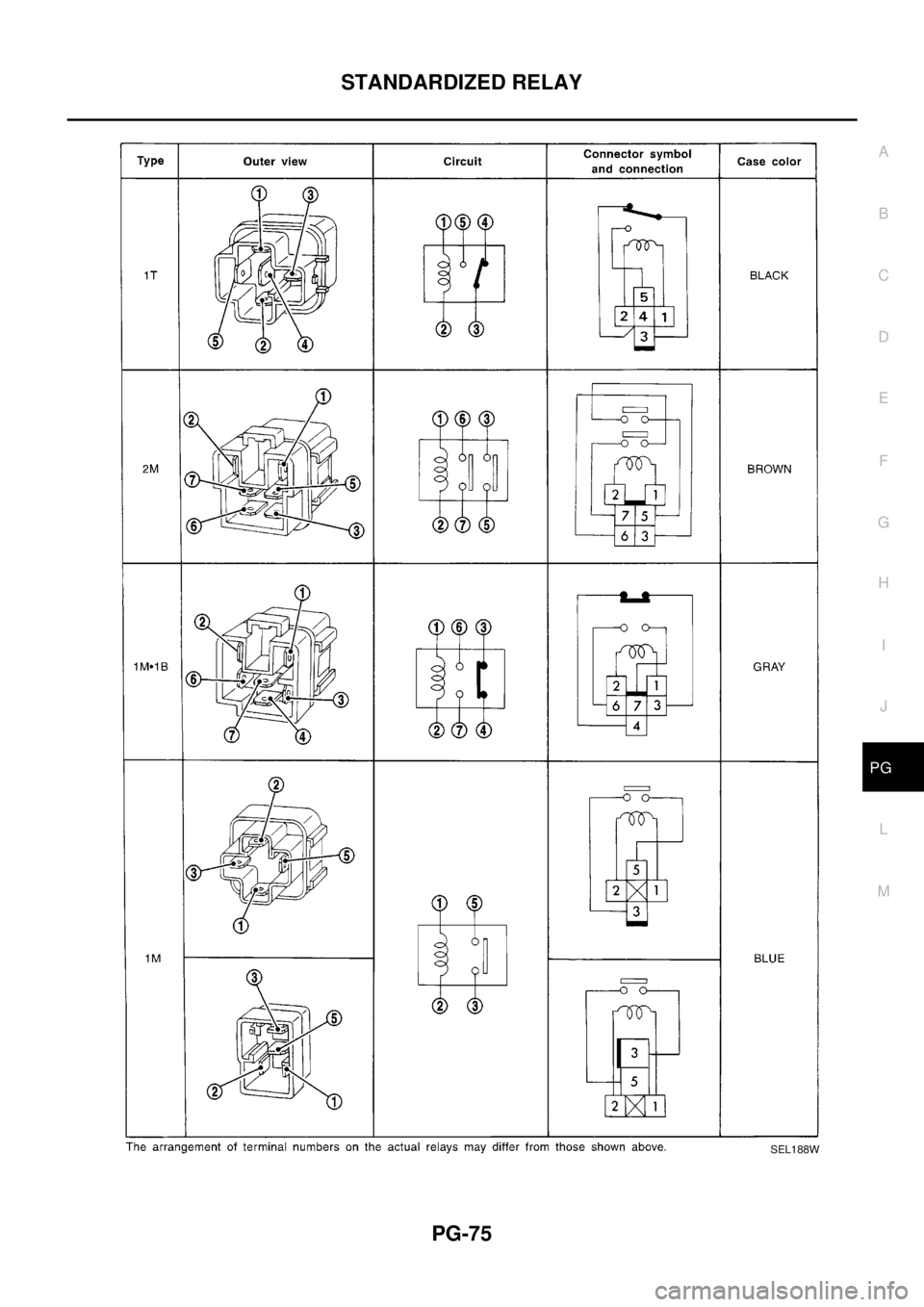
STANDARDIZED RELAY
PG-75
C
D
E
F
G
H
I
J
L
MA
B
PG
SEL188W
Page 2752 of 3066
PG-76
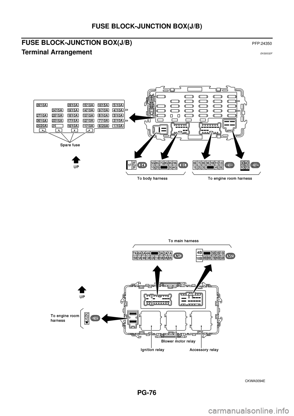
FUSE BLOCK-JUNCTION BOX(J/B)
FUSE BLOCK-JUNCTION BOX(J/B)
PFP:24350
Terminal ArrangementEKS0032F
CKWA0094E
Page 2753 of 3066
FUSE AND FUSIBLE LINK BOX
PG-77
C
D
E
F
G
H
I
J
L
MA
B
PG
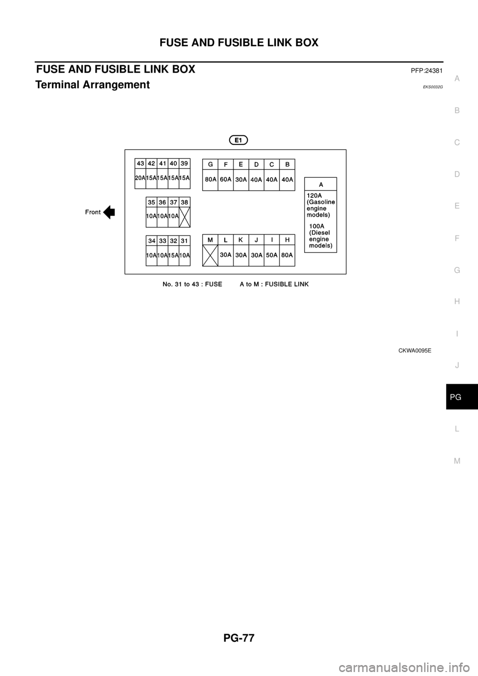
FUSE AND FUSIBLE LINK BOXPFP:24381
Terminal ArrangementEKS0032G
CKWA0095E
Page 2754 of 3066
PG-78
FUSE AND FUSIBLE LINK BOX
Page 2755 of 3066
PR-1
PROPELLER SHAFT
D DRIVELINE/AXLE
CONTENTS
C
E
F
G
H
I
J
K
L
M
SECTION
A
B
PR
PROPELLER SHAFT
REAR PROPELLER SHAFT ...................................... 2
On-Vehicle Inspection .............................................. 2
PROPELLER SHAFT RUNOUT INSPECTION..... 2
APPEARANCE AND NOISE INSPECTION .......... 2
Removal and Installation .......................................... 3
REMOVAL ............................................................. 3
INSPECTION AFTER REMOVAL ......................... 3
INSTALLATION ..................................................... 3SERVICE DATA AND SPECIFICATIONS (SDS) ........ 5
General Specifications .............................................. 5
Propeller Shaft Axial Play ......................................... 5
Propeller Shaft Vibration ........................................... 5
Page 2756 of 3066
PR-2
REAR PROPELLER SHAFT
REAR PROPELLER SHAFT
PFP:37000
On-Vehicle InspectionEDS00051
PROPELLER SHAFT RUNOUT INSPECTION
If vibration occurs during driving at high speed, check for propeller shaft runout first.
1. Lift vehicle.
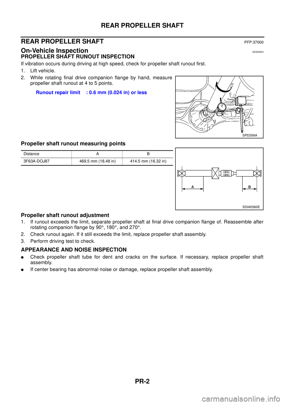
2. While rotating final drive companion flange by hand, measure
propeller shaft runout at 4 to 5 points.
Propeller shaft runout measuring points
Propeller shaft runout adjustment
1. If runout exceeds the limit, separate propeller shaft at final drive companion flange of. Reassemble after
rotating companion flange by 90°, 180°, and 270°.
2. Check runout again. If it still exceeds the limit, replace propeller shaft assembly.
3. Perform driving test to check.
APPEARANCE AND NOISE INSPECTION
lCheck propeller shaft tube for dent and cracks on the surface. If necessary, replace propeller shaft
assembly.
lIf center bearing has abnormal noise or damage, replace propeller shaft assembly.Runout repair limit : 0.6 mm (0.024 in) or less
SPD356A
Distance A B
3F63A-DOJ87 469.5 mm (18.48 in) 414.5 mm (16.32 in)
SDIA0560E
Page 2757 of 3066
REAR PROPELLER SHAFT
PR-3
C
E
F
G
H
I
J
K
L
MA
B
PR
Removal and InstallationEDS00052
REMOVAL
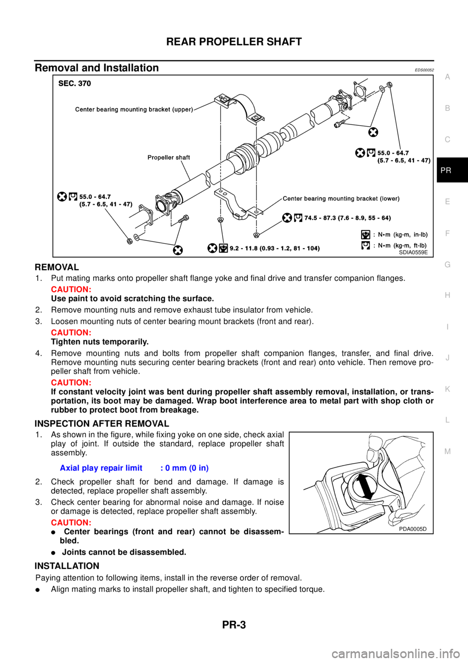
1. Put mating marks onto propeller shaft flange yoke and final drive and transfer companion flanges.
CAUTION:
Use paint to avoid scratching the surface.
2. Remove mounting nuts and remove exhaust tube insulator from vehicle.
3. Loosen mounting nuts of center bearing mount brackets (front and rear).
CAUTION:
Tighten nuts temporarily.
4. Remove mounting nuts and bolts from propeller shaft companion flanges, transfer, and final drive.
Remove mounting nuts securing center bearing brackets (front and rear) onto vehicle. Then remove pro-
peller shaft from vehicle.
CAUTION:
If constant velocity joint was bent during propeller shaft assembly removal, installation, or trans-
portation, its boot may be damaged. Wrap boot interference area to metal part with shop cloth or
rubber to protect boot from breakage.
INSPECTION AFTER REMOVAL
1. As shown in the figure, while fixing yoke on one side, check axial
play of joint. If outside the standard, replace propeller shaft
assembly.
2. Check propeller shaft for bend and damage. If damage is
detected, replace propeller shaft assembly.
3. Check center bearing for abnormal noise and damage. If noise
or damage is detected, replace propeller shaft assembly.
CAUTION:
lCenter bearings (front and rear) cannot be disassem-
bled.
lJoints cannot be disassembled.
INSTALLATION
Paying attention to following items, install in the reverse order of removal.
lAlign mating marks to install propeller shaft, and tighten to specified torque.
SDIA0559E
Axial play repair limit : 0 mm (0 in)
PDA0005D
Page 2758 of 3066
PR-4
REAR PROPELLER SHAFT
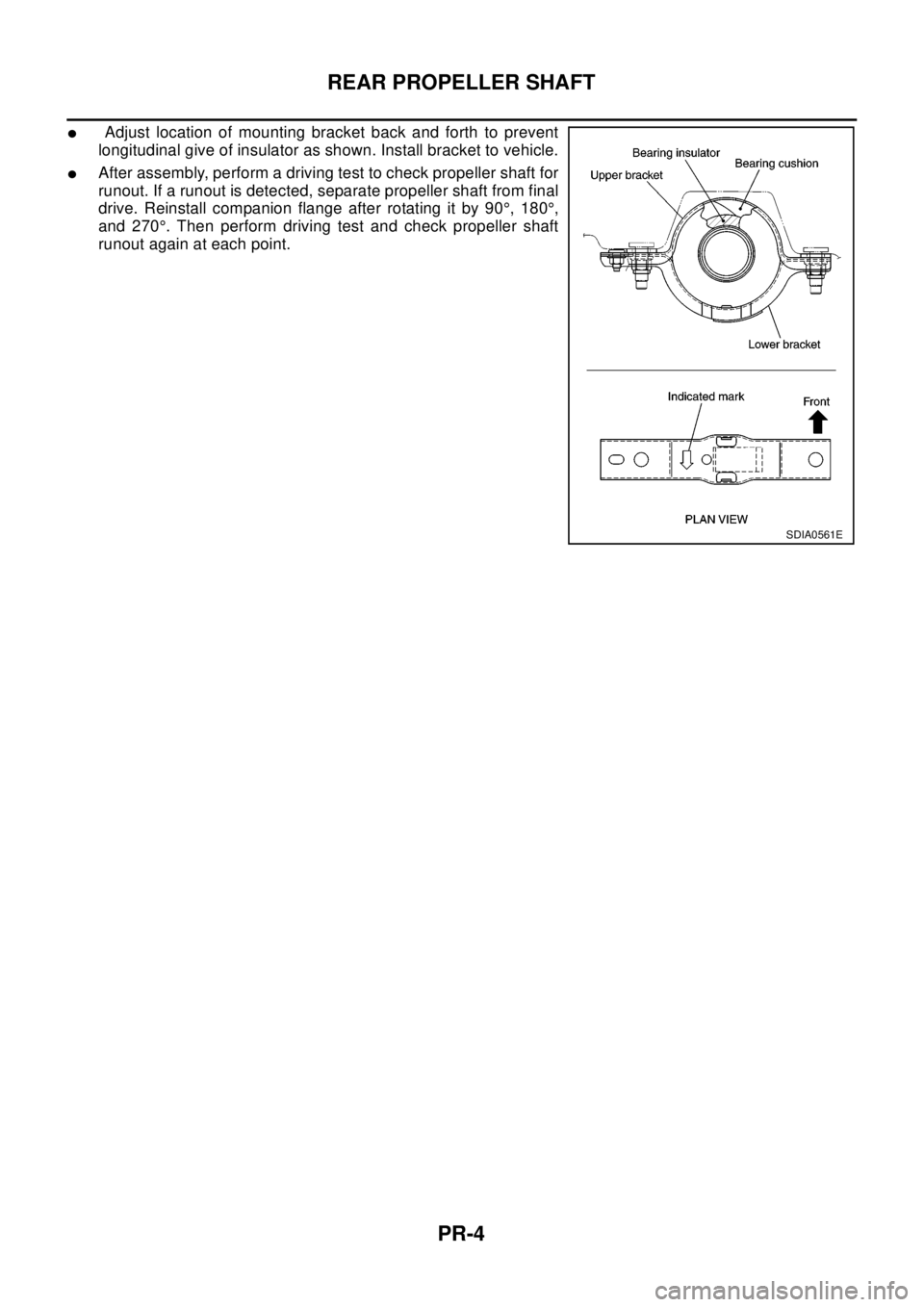
lAdjust location of mounting bracket back and forth to prevent
longitudinal give of insulator as shown. Install bracket to vehicle.
lAfter assembly, perform a driving test to check propeller shaft for
runout. If a runout is detected, separate propeller shaft from final
drive. Reinstall companion flange after rotating it by 90°,180°,
and 270°. Then perform driving test and check propeller shaft
runout again at each point.
SDIA0561E
Page 2759 of 3066
SERVICE DATA AND SPECIFICATIONS (SDS)
PR-5
C
E
F
G
H
I
J
K
L
MA
B
PR
SERVICE DATA AND SPECIFICATIONS (SDS)PFP:00030
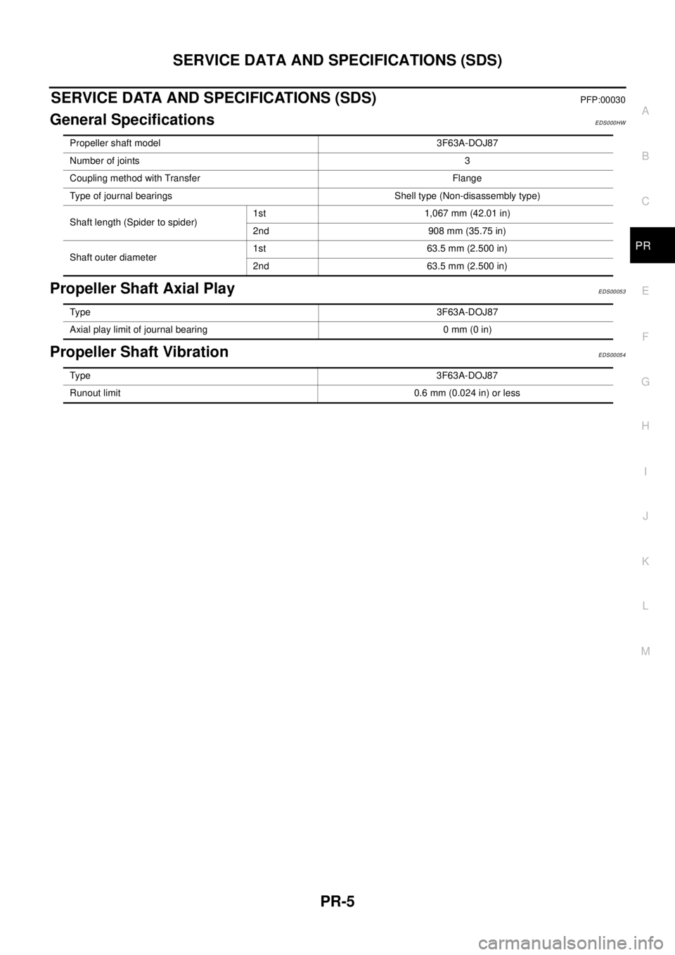
General SpecificationsEDS000HW
Propeller Shaft Axial PlayEDS00053
Propeller Shaft VibrationEDS00054
Propeller shaft model 3F63A-DOJ87
Number of joints3
Coupling method with Transfer Flange
Type of journal bearings Shell type (Non-disassembly type)
Shaft length (Spider to spider)1st 1,067 mm (42.01 in)
2nd 908 mm (35.75 in)
Shaft outer diameter1st 63.5 mm (2.500 in)
2nd 63.5 mm (2.500 in)
Ty pe3F63A-DOJ87
Axial play limit of journal bearing 0 mm (0 in)
Ty pe3F63A-DOJ87
Runout limit 0.6 mm (0.024 in) or less
Page 2760 of 3066
PR-6
SERVICE DATA AND SPECIFICATIONS (SDS)
Trending: wheelbase, fuses, fuel filter location, height, battery capacity, octane, diagram
