NISSAN X-TRAIL 2003 Electronic Repair Manual
Manufacturer: NISSAN, Model Year: 2003, Model line: X-TRAIL, Model: NISSAN X-TRAIL 2003Pages: 3066, PDF Size: 51.47 MB
Page 2771 of 3066
STEERING COLUMN
PS-11
C
D
E
F
H
I
J
K
L
MA
B
PS
INSPECTION AFTER DISASSEMBLY.
lIf steering wheel does not turn smoothly, check the following and replace malfunctioning part.
1. Check column shaft bearing for damage and other malfunctions. Lubricate with grease or replace column
shaft if necessary.
2. Check jacket tube for deformation and cracks, and replace if necessary.
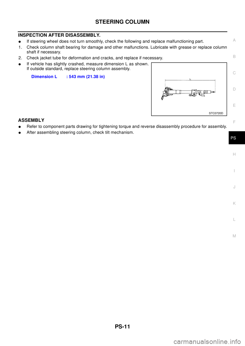
lIf vehicle has slightly crashed, measure dimension L as shown.
If outside standard, replace steering column assembly.
ASSEMBLY
lRefer to component parts drawing for tightening torque and reverse disassembly procedure for assembly.
lAfter assembling steering column, check tilt mechanism.Dimension L : 543 mm (21.38 in)
STC0720D
Page 2772 of 3066
PS-12
POWER STEERING GEAR AND LINKAGE
POWER STEERING GEAR AND LINKAGE
PFP:49001
Removal and InstallationEGS0004I
REMOVAL
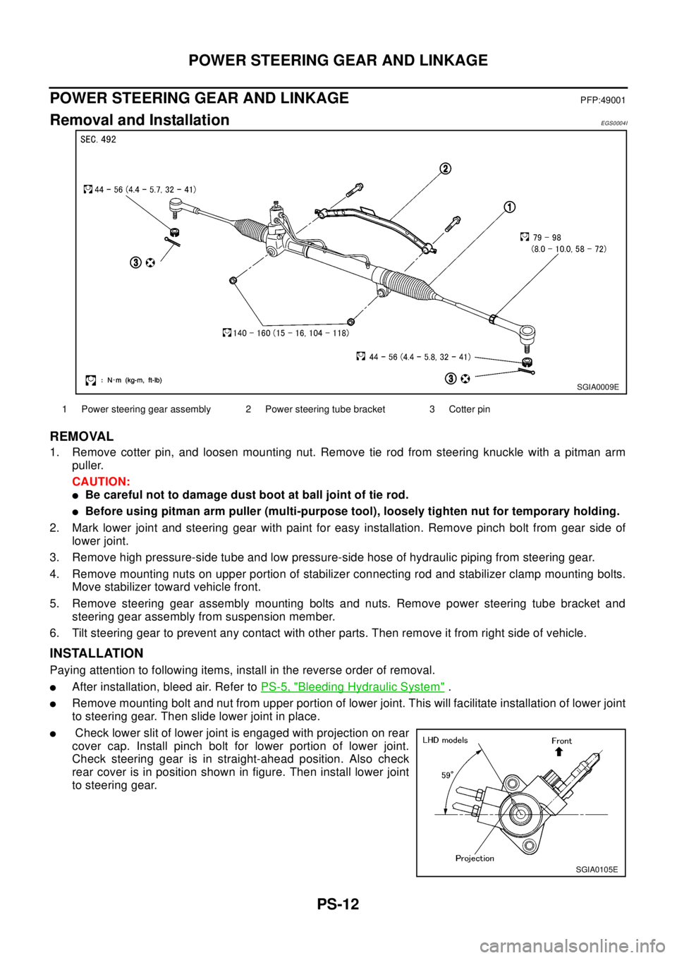
1. Remove cotter pin, and loosen mounting nut. Remove tie rod from steering knuckle with a pitman arm
puller.
CAUTION:
lBe careful not to damage dust boot at ball joint of tie rod.
lBefore using pitman arm puller (multi-purpose tool), loosely tighten nut for temporary holding.
2. Mark lower joint and steering gear with paint for easy installation. Remove pinch bolt from gear side of
lower joint.
3. Remove high pressure-side tube and low pressure-side hose of hydraulic piping from steering gear.
4. Remove mounting nuts on upper portion of stabilizer connecting rod and stabilizer clamp mounting bolts.
Move stabilizer toward vehicle front.
5. Remove steering gear assembly mounting bolts and nuts. Remove power steering tube bracket and
steering gear assembly from suspension member.
6. Tilt steering gear to prevent any contact with other parts. Then remove it from right side of vehicle.
INSTALLATION
Paying attention to following items, install in the reverse order of removal.
lAfter installation, bleed air. Refer toPS-5, "Bleeding Hydraulic System".
lRemove mounting bolt and nut from upper portion of lower joint. This will facilitate installation of lower joint
to steering gear. Then slide lower joint in place.
lCheck lower slit of lower joint is engaged with projection on rear
cover cap. Install pinch bolt for lower portion of lower joint.
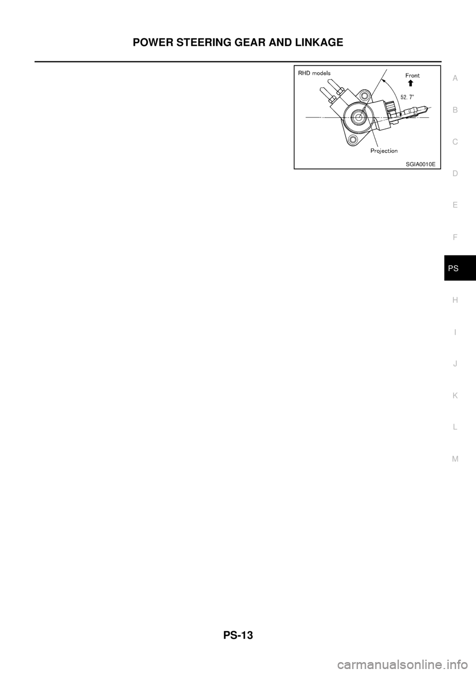
Check steering gear is in straight-ahead position. Also check
rear cover is in position shown in figure. Then install lower joint
to steering gear.
SGIA0009E
1 Power steering gear assembly 2 Power steering tube bracket 3 Cotter pin
SGIA0105E
Page 2773 of 3066
POWER STEERING GEAR AND LINKAGE
PS-13
C
D
E
F
H
I
J
K
L
MA
B
PS
SGIA0010E
Page 2774 of 3066
PS-14
POWER STEERING GEAR AND LINKAGE
Components
EGS0004J
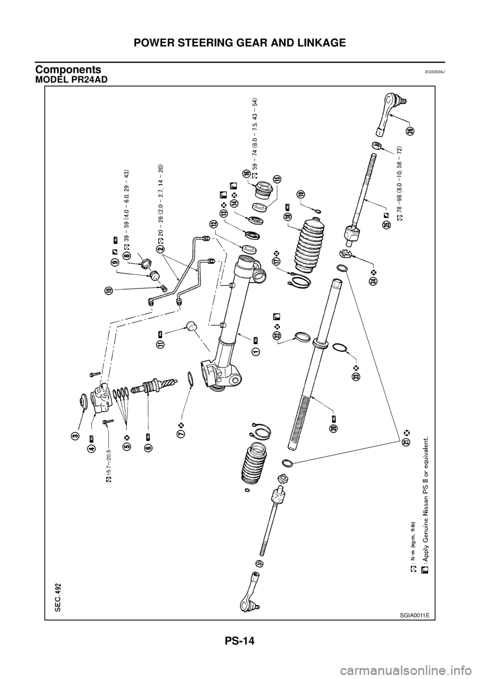
MODEL PR24AD
SGIA0011E
Page 2775 of 3066
POWER STEERING GEAR AND LINKAGE
PS-15
C
D
E
F
H
I
J
K
L
MA
B
PS
Disassembly and AssemblyEGS0004K
DISASSEMBLY
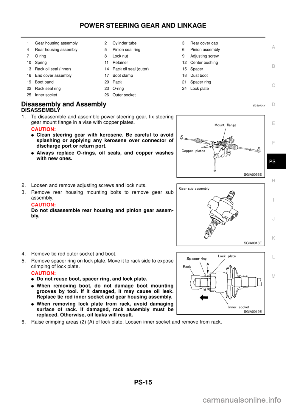
1. To disassemble and assemble power steering gear, fix steering
gear mount flange in a vise with copper plates.
CAUTION:
lClean steering gear with kerosene. Be careful to avoid
splashing or applying any kerosene over connector of
discharge port or return port.
lAlways replace O-rings, oil seals, and copper washes
with new ones.
2. Loosen and remove adjusting screws and lock nuts.
3. Remove rear housing mounting bolts to remove gear sub
assembly.
CAUTION:
Do not disassemble rear housing and pinion gear assem-
bly.
4. Remove tie rod outer socket and boot.
5. Remove spacer ring on lock plate. Move it to rack side to expose
crimping of lock plate.
CAUTION:
lDo not reuse boot, spacer ring, and lock plate.
lWhen removing boot, do not damage boot mounting
grooves by tool. If it damaged, it may cause oil leak.
Replace tie rod inner socket and gear housing assembly.
lWhen removing lock plate from rack, avoid damaging
surface of rack. If damaged, rack assembly must be
replaced. Otherwise, oil leaks will result.
6. Raise crimping areas (2) (A) of lock plate. Loosen inner socket and remove from rack.
1 Gear housing assembly 2 Cylinder tube 3 Rear cover cap
4 Rear housing assembly 5 Pinion seal ring 6 Pinion assembly
7 O ring 8 Lock nut 9 Adjusting screw
10 Spring 11 Retainer 12 Center bushing
13 Rack oil seal (inner) 14 Rack oil seal (outer) 15 Spacer
16 End cover assembly 17 Boot clamp 18 Dust boot
19 Boot band 20 Rack 21 Spacer ring
22 Rack seal ring 23 O-ring 24 Lock plate
25 Inner socket 26 Outer socket
SGIA0056E
SGIA0018E
SGIA0019E
Page 2776 of 3066
PS-16
POWER STEERING GEAR AND LINKAGE
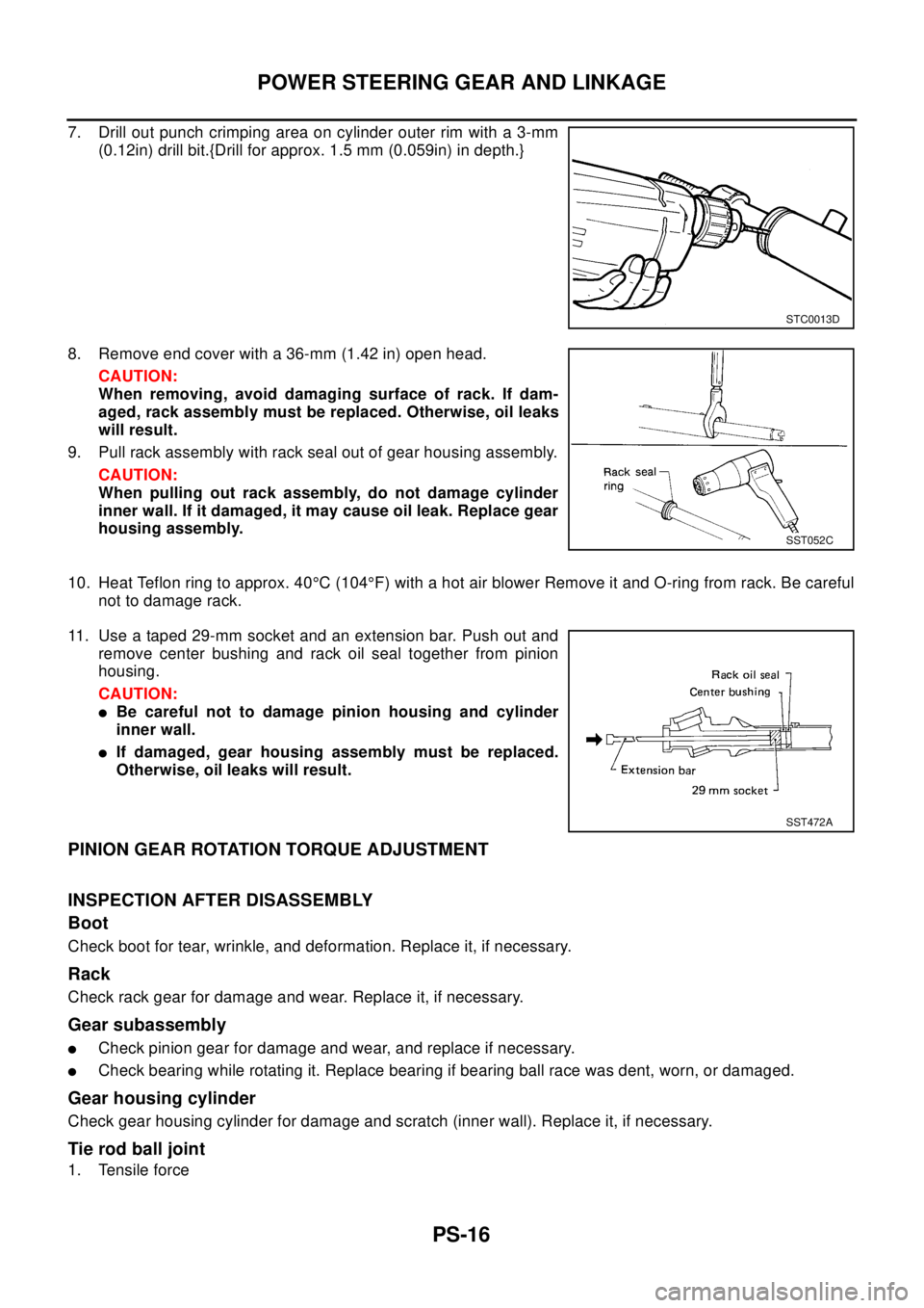
7. Drill out punch crimping area on cylinder outer rim with a 3-mm
(0.12in) drill bit.{Drill for approx. 1.5 mm (0.059in) in depth.}
8. Remove end cover with a 36-mm (1.42 in) open head.
CAUTION:
When removing, avoid damaging surface of rack. If dam-
aged, rack assembly must be replaced. Otherwise, oil leaks
will result.
9. Pull rack assembly with rack seal out of gear housing assembly.
CAUTION:
When pulling out rack assembly, do not damage cylinder
inner wall. If it damaged, it may cause oil leak. Replace gear
housing assembly.
10. Heat Teflon ring to approx. 40°C (104°F) with a hot air blower Remove it and O-ring from rack. Be careful
not to damage rack.
11. Use a taped 29-mm socket and an extension bar. Push out and
remove center bushing and rack oil seal together from pinion
housing.
CAUTION:
lBe careful not to damage pinion housing and cylinder
inner wall.
lIf damaged, gear housing assembly must be replaced.
Otherwise, oil leaks will result.
PINION GEAR ROTATION TORQUE ADJUSTMENT
INSPECTION AFTER DISASSEMBLY
Boot
Check boot for tear, wrinkle, and deformation. Replace it, if necessary.
Rack
Check rack gear for damage and wear. Replace it, if necessary.
Gear subassembly
lCheck pinion gear for damage and wear, and replace if necessary.
lCheck bearing while rotating it. Replace bearing if bearing ball race was dent, worn, or damaged.
Gear housing cylinder
Check gear housing cylinder for damage and scratch (inner wall). Replace it, if necessary.
Tie rod ball joint
1. Tensile force
STC0013D
SST052C
SST472A
Page 2777 of 3066
POWER STEERING GEAR AND LINKAGE
PS-17
C
D
E
F
H
I
J
K
L
MA
B
PS
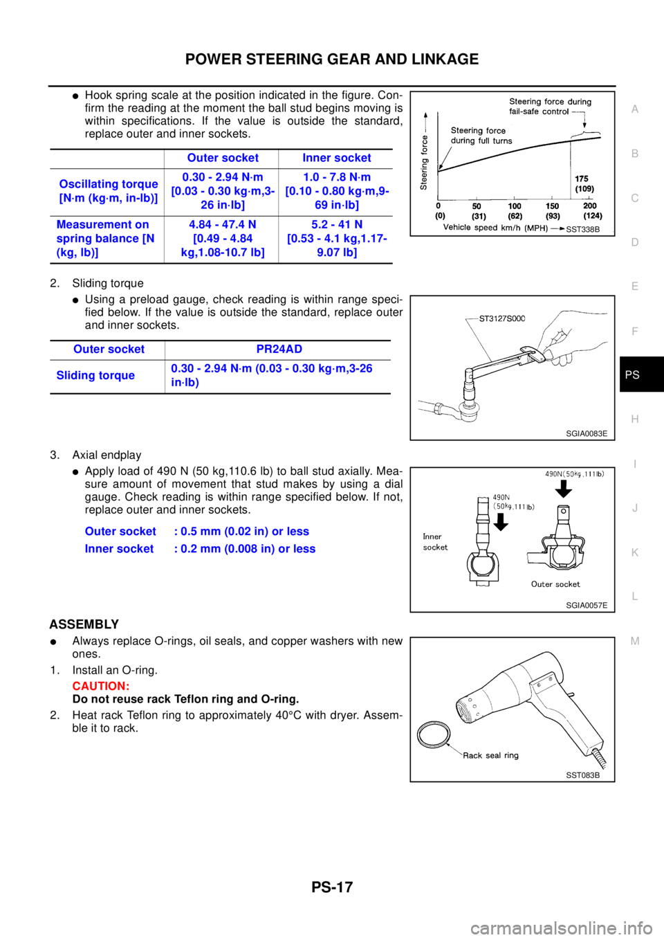
lHook spring scale at the position indicated in the figure. Con-
firm the reading at the moment the ball stud begins moving is
within specifications. If the value is outside the standard,
replace outer and inner sockets.
2. Sliding torque
lUsing a preload gauge, check reading is within range speci-
fied below. If the value is outside the standard, replace outer
and inner sockets.
3. Axial endplay
lApply load of 490 N (50 kg,110.6 lb) to ball stud axially. Mea-
sure amount of movement that stud makes by using a dial
gauge. Check reading is within range specified below. If not,
replace outer and inner sockets.
ASSEMBLY
lAlways replace O-rings, oil seals, and copper washers with new
ones.
1. Install an O-ring.
CAUTION:
Do not reuse rack Teflon ring and O-ring.
2. Heat rack Teflon ring to approximately 40°C with dryer. Assem-
ble it to rack.Outer socket Inner socket
Oscillating torque
[N·m (kg·m, in-lb)]0.30 - 2.94 N·m
[0.03 - 0.30 kg·m,3-
26 in·lb]1.0 - 7.8 N·m
[0.10 - 0.80 kg·m,9-
69 in·lb]
Measurement on
spring balance [N
(kg, lb)]4.84 - 47.4 N
[0.49 - 4.84
kg,1.08-10.7 lb]5.2 - 41 N
[0.53 - 4.1 kg,1.17-
9.07 lb]
SST338B
Outer socket PR24AD
Sliding torque0.30 - 2.94 N·m (0.03 - 0.30 kg·m,3-26
in·lb)
SGIA0083E
Outer socket : 0.5 mm (0.02 in) or less
Inner socket : 0.2 mm (0.008 in) or less
SGIA0057E
SST083B
Page 2778 of 3066
PS-18
POWER STEERING GEAR AND LINKAGE
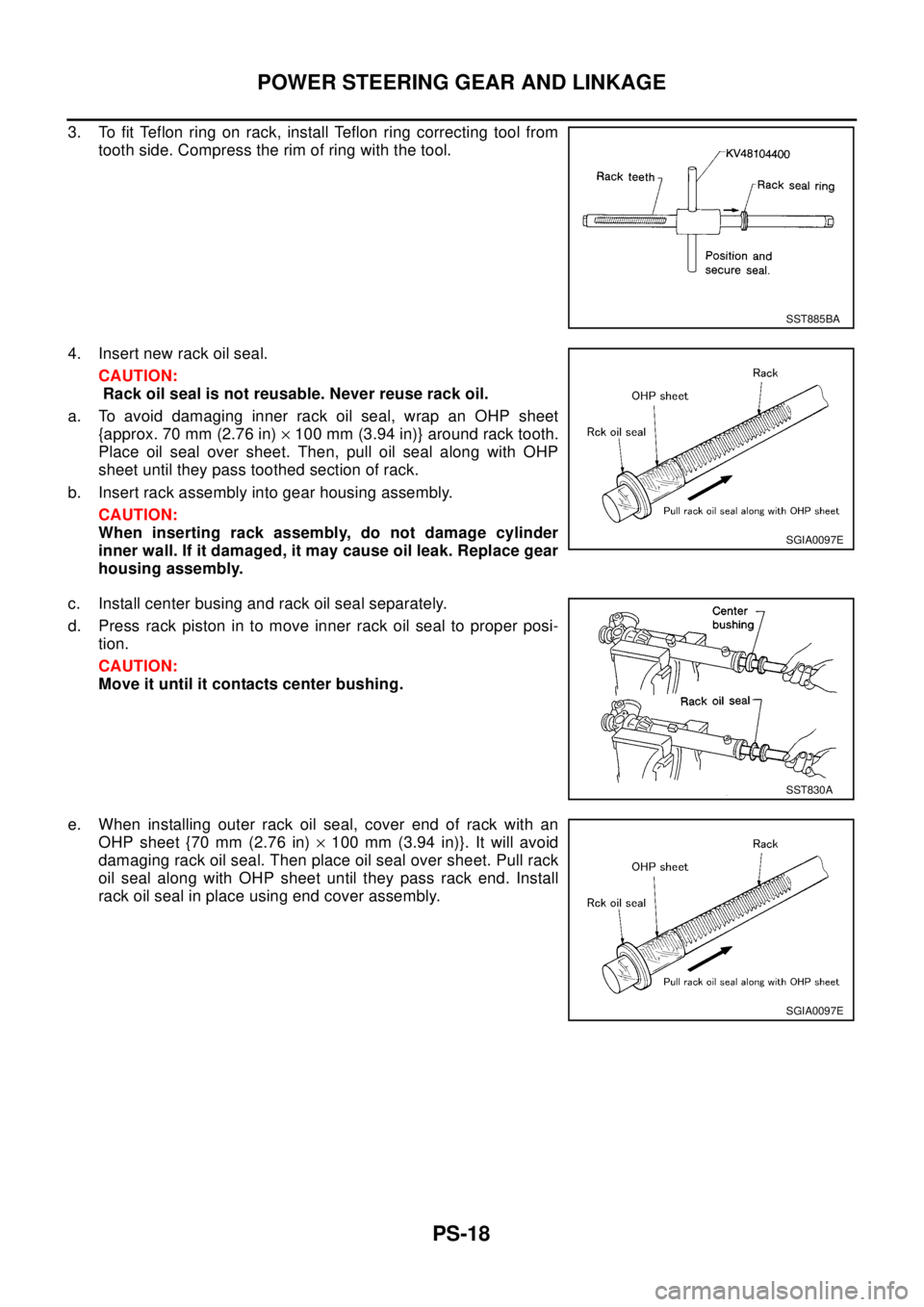
3. To fit Teflon ring on rack, install Teflon ring correcting tool from
tooth side. Compress the rim of ring with the tool.
4. Insert new rack oil seal.
CAUTION:
Rack oil seal is not reusable. Never reuse rack oil.
a. To avoid damaging inner rack oil seal, wrap an OHP sheet
{approx. 70 mm (2.76 in)´100 mm (3.94 in)} around rack tooth.
Place oil seal over sheet. Then, pull oil seal along with OHP
sheet until they pass toothed section of rack.
b. Insert rack assembly into gear housing assembly.
CAUTION:
When inserting rack assembly, do not damage cylinder
inner wall. If it damaged, it may cause oil leak. Replace gear
housing assembly.
c. Install center busing and rack oil seal separately.
d. Press rack piston in to move inner rack oil seal to proper posi-
tion.
CAUTION:
Move it until it contacts center bushing.
e. When installing outer rack oil seal, cover end of rack with an
OHP sheet {70 mm (2.76 in)´100 mm (3.94 in)}. It will avoid
damaging rack oil seal. Then place oil seal over sheet. Pull rack
oil seal along with OHP sheet until they pass rack end. Install
rack oil seal in place using end cover assembly.
SST885BA
SGIA0097E
SST830A
SGIA0097E
Page 2779 of 3066
POWER STEERING GEAR AND LINKAGE
PS-19
C
D
E
F
H
I
J
K
L
MA
B
PS
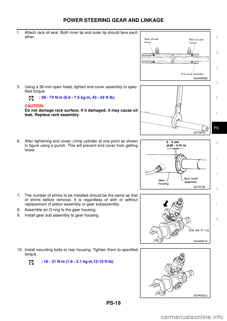
f. Attach rack oil seal. Both inner lip and outer lip should face each
other.
5. Using a 36-mm open head, tighten end cover assembly to spec-
ified torque.
CAUTION:
Do not damage rack surface. If it damaged, it may cause oil
leak. Replace rack assembly.
6. After tightening end cover, crimp cylinder at one point as shown
in figure using a punch. This will prevent end cover from getting
loose.
7. The number of shims to be installed should be the same as that
of shims before removal. It is regardless of with or without
replacement of piston assembly or gear subassembly.
8. Assemble an O-ring to the gear housing.
9. Install gear sub assembly to gear housing.
10. Install mounting bolts to rear housing. Tighten them to specified
torque.
11 .
SGIA0058E
: 59 - 74 N·m (6.0 - 7.5 kg·m, 43 - 54 ft·lb)
SST081B
SST073B
SGIA0021E
: 16 - 21 N·m (1.6 - 2.1 kg·m,12-15 ft·lb)
SGIA0022J
Page 2780 of 3066
PS-20
POWER STEERING GEAR AND LINKAGE
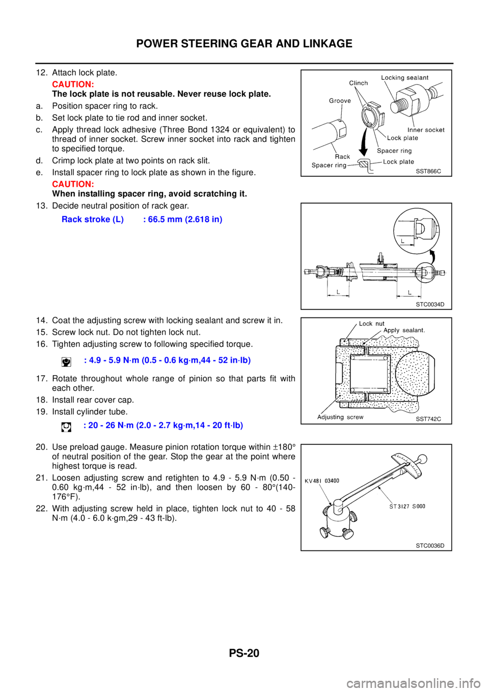
12. Attach lock plate.
CAUTION:
The lock plate is not reusable. Never reuse lock plate.
a. Position spacer ring to rack.
b. Set lock plate to tie rod and inner socket.
c. Apply thread lock adhesive (Three Bond 1324 or equivalent) to
thread of inner socket. Screw inner socket into rack and tighten
to specified torque.
d. Crimp lock plate at two points on rack slit.
e. Install spacer ring to lock plate as shown in the figure.
CAUTION:
When installing spacer ring, avoid scratching it.
13. Decide neutral position of rack gear.
14. Coat the adjusting screw with locking sealant and screw it in.
15. Screw lock nut. Do not tighten lock nut.
16. Tighten adjusting screw to following specified torque.
17. Rotate throughout whole range of pinion so that parts fit with
each other.
18. Install rear cover cap.
19. Install cylinder tube.
20. Use preload gauge. Measure pinion rotation torque within±180°
of neutral position of the gear. Stop the gear at the point where
highest torque is read.
21. Loosen adjusting screw and retighten to 4.9 - 5.9 N·m (0.50 -
0.60 kg·m,44 - 52 in·lb), and then loosen by 60 - 80°(140-
176°F).
22. With adjusting screw held in place, tighten lock nut to 40 - 58
N·m (4.0 - 6.0 k·gm,29 - 43 ft-lb).Rack stroke (L) : 66.5 mm (2.618 in)
SST866C
STC0034D
: 4.9 - 5.9 N·m (0.5 - 0.6 kg·m,44 - 52 in·lb)
:20-26N·m(2.0-2.7kg·m,14-20ft·lb)
SST742C
STC0036D