NISSAN X-TRAIL 2003 Electronic Repair Manual
X-TRAIL 2003
NISSAN
NISSAN
https://www.carmanualsonline.info/img/5/57402/w960_57402-0.png
NISSAN X-TRAIL 2003 Electronic Repair Manual
Trending: fuse chart, coolant temperature, clock reset, heating, fuel cap release, air conditioning, steering
Page 2891 of 3066
CHARGING SYSTEM
SC-19
C
D
E
F
G
H
I
J
L
MA
B
SC
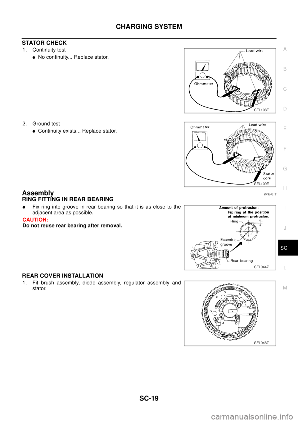
STATOR CHECK
1. Continuity test
lNo continuity... Replace stator.
2. Ground test
lContinuity exists... Replace stator.
AssemblyEKS0031E
RING FITTING IN REAR BEARING
lFix ring into groove in rear bearing so that it is as close to the
adjacent area as possible.
CAUTION:
Do not reuse rear bearing after removal.
REAR COVER INSTALLATION
1. Fit brush assembly, diode assembly, regulator assembly and
stator.
SEL108E
SEL109E
SEL044Z
SEL048Z
Page 2892 of 3066
SC-20
CHARGING SYSTEM
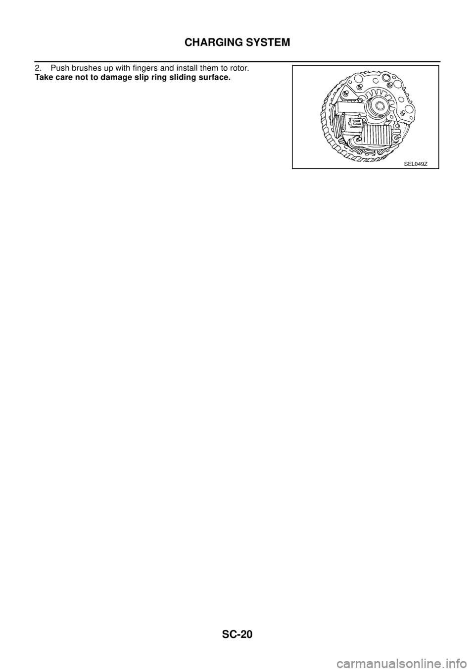
2. Push brushes up with fingers and install them to rotor.
Take care not to damage slip ring sliding surface.
SEL049Z
Page 2893 of 3066
STARTING SYSTEM
SC-21
C
D
E
F
G
H
I
J
L
MA
B
SC
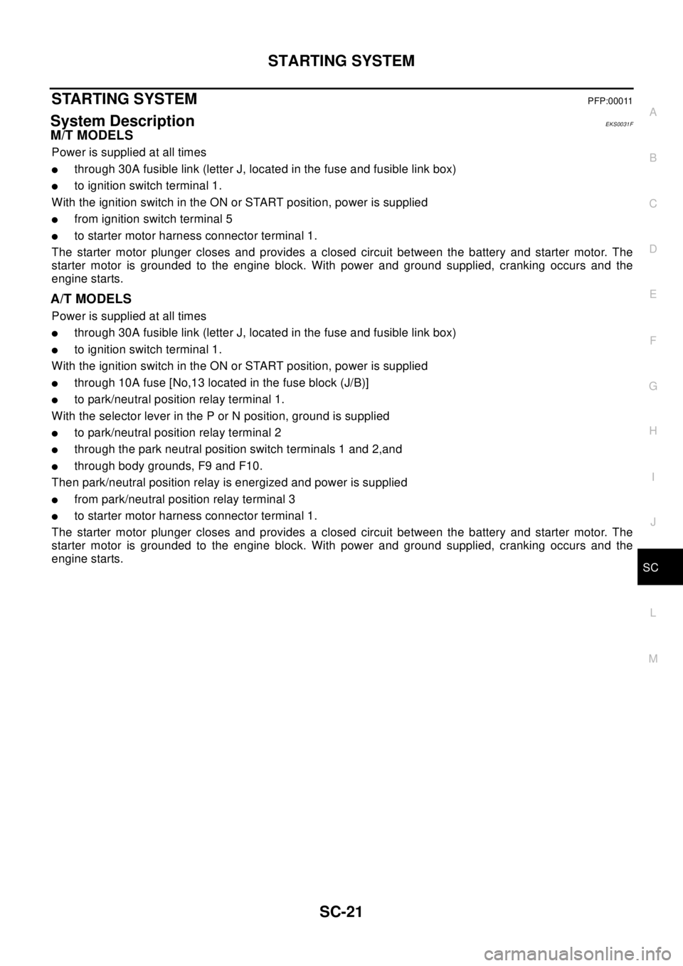
STARTING SYSTEMPFP:00011
System DescriptionEKS0031F
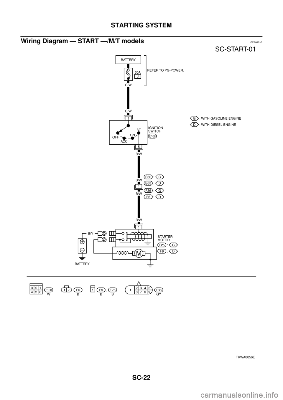
M/T MODELS
Power is supplied at all times
lthrough 30A fusible link (letter J, located in the fuse and fusible link box)
lto ignition switch terminal 1.
With the ignition switch in the ON or START position, power is supplied
lfrom ignition switch terminal 5
lto starter motor harness connector terminal 1.
The starter motor plunger closes and provides a closed circuit between the battery and starter motor. The
starter motor is grounded to the engine block. With power and ground supplied, cranking occurs and the
engine starts.
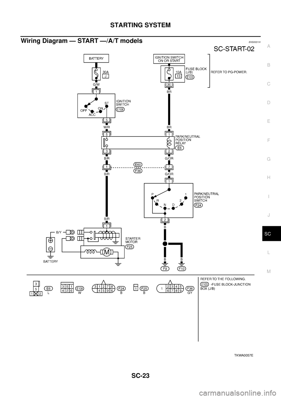
A/T MODELS
Power is supplied at all times
lthrough 30A fusible link (letter J, located in the fuse and fusible link box)
lto ignition switch terminal 1.
With the ignition switch in the ON or START position, power is supplied
lthrough 10A fuse [No,13 located in the fuse block (J/B)]
lto park/neutral position relay terminal 1.
With the selector lever in the P or N position, ground is supplied
lto park/neutral position relay terminal 2
lthrough the park neutral position switch terminals 1 and 2,and
lthrough body grounds, F9 and F10.
Then park/neutral position relay is energized and power is supplied
lfrom park/neutral position relay terminal 3
lto starter motor harness connector terminal 1.
The starter motor plunger closes and provides a closed circuit between the battery and starter motor. The
starter motor is grounded to the engine block. With power and ground supplied, cranking occurs and the
engine starts.
Page 2894 of 3066
SC-22
STARTING SYSTEM
Wiring Diagram — START —/M/T models
EKS0031G
TKWA0056E
Page 2895 of 3066
STARTING SYSTEM
SC-23
C
D
E
F
G
H
I
J
L
MA
B
SC
Wiring Diagram — START —/A/T modelsEKS0031H
TKWA0057E
Page 2896 of 3066
SC-24
STARTING SYSTEM
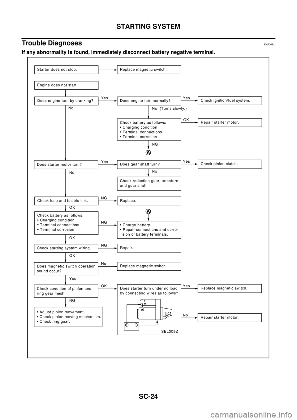
Trouble Diagnoses
EKS0031I
If any abnormality is found, immediately disconnect battery negative terminal.
Page 2897 of 3066
STARTING SYSTEM
SC-25
C
D
E
F
G
H
I
J
L
MA
B
SC
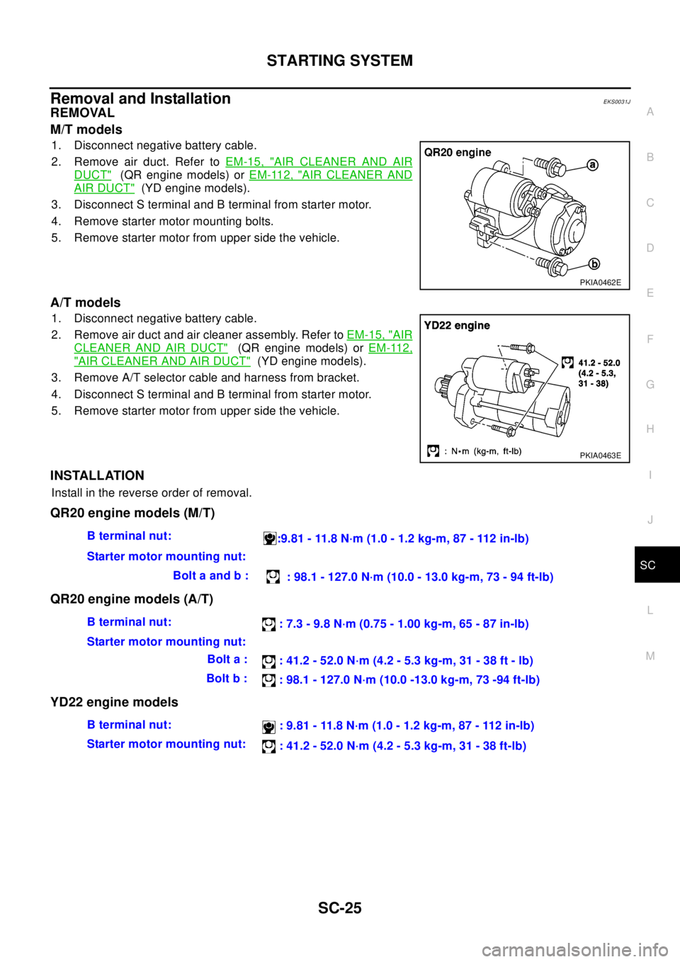
Removal and InstallationEKS0031J
REMOVAL
M/T models
1. Disconnect negative battery cable.
2. Remove air duct. Refer toEM-15, "
AIR CLEANER AND AIR
DUCT"(QR engine models) orEM-112, "AIR CLEANER AND
AIR DUCT"(YD engine models).
3. Disconnect S terminal and B terminal from starter motor.
4. Remove starter motor mounting bolts.
5. Remove starter motor from upper side the vehicle.
A/T models
1. Disconnect negative battery cable.
2. Remove air duct and air cleaner assembly. Refer toEM-15, "
AIR
CLEANER AND AIR DUCT"(QR engine models) orEM-112,
"AIR CLEANER AND AIR DUCT"(YD engine models).
3. Remove A/T selector cable and harness from bracket.
4. Disconnect S terminal and B terminal from starter motor.
5. Remove starter motor from upper side the vehicle.
INSTALLATION
Install in the reverse order of removal.
QR20 engine models (M/T)
QR20 engine models (A/T)
YD22 engine models
PKIA0462E
PKIA0463E
Bterminalnut:
:9.81 - 11.8 N·m (1.0 - 1.2 kg-m, 87 - 112 in-lb)
Starter motor mounting nut:
Bolt a and b :
: 98.1 - 127.0 N·m (10.0 - 13.0 kg-m, 73 - 94 ft-lb)
Bterminalnut:
: 7.3 - 9.8 N·m (0.75 - 1.00 kg-m, 65 - 87 in-lb)
Starter motor mounting nut:
Bolt a :
: 41.2 - 52.0 N·m (4.2 - 5.3 kg-m, 31 - 38 ft - lb)
Bolt b :
: 98.1 - 127.0 N·m (10.0 -13.0 kg-m, 73 -94 ft-lb)
Bterminalnut:
: 9.81 - 11.8 N·m (1.0 - 1.2 kg-m, 87 - 112 in-lb)
Starter motor mounting nut:
: 41.2 - 52.0 N·m (4.2 - 5.3 kg-m, 31 - 38 ft-lb)
Page 2898 of 3066
SC-26
STARTING SYSTEM
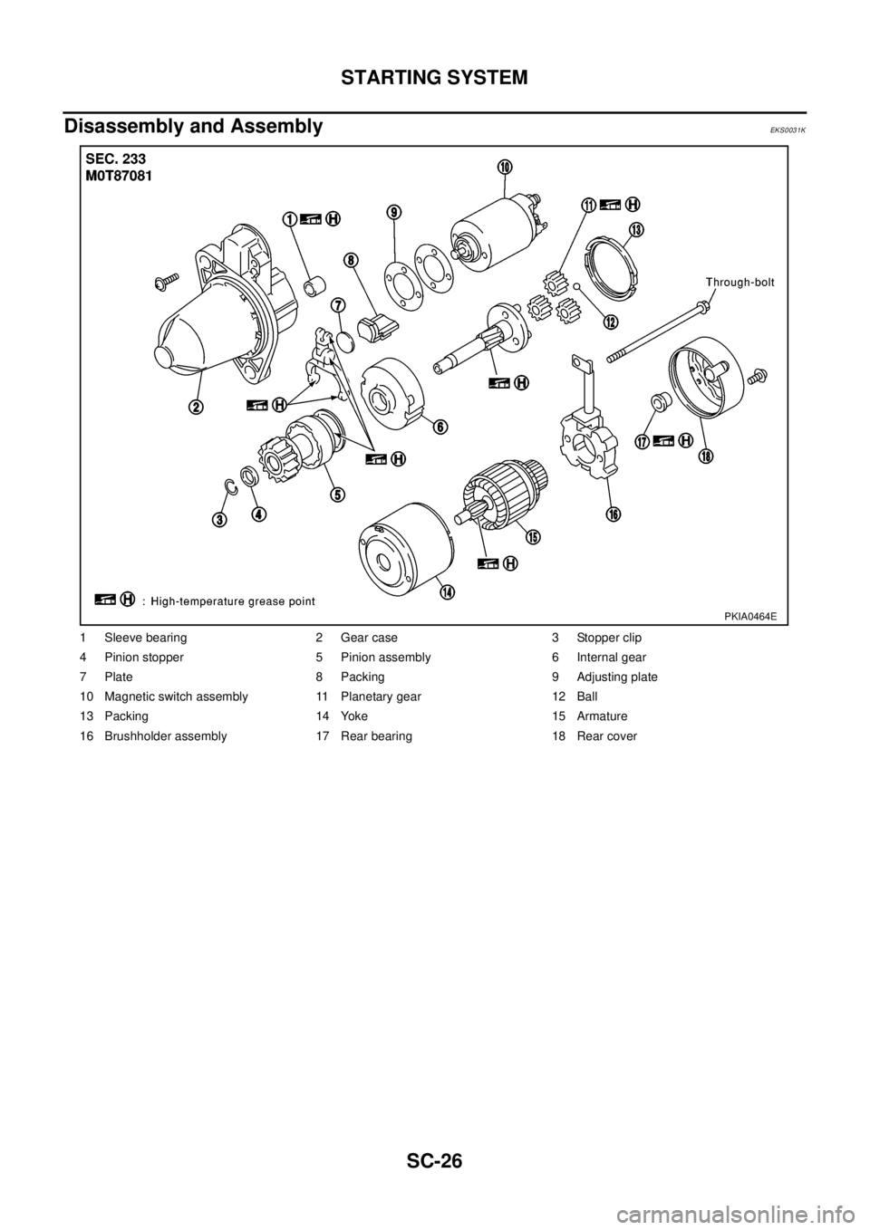
Disassembly and Assembly
EKS0031K
1 Sleeve bearing 2 Gear case 3 Stopper clip
4 Pinion stopper 5 Pinion assembly 6 Internal gear
7 Plate 8 Packing 9 Adjusting plate
10 Magnetic switch assembly 11 Planetary gear 12 Ball
13 Packing 14 Yoke 15 Armature
16 Brushholder assembly 17 Rear bearing 18 Rear cover
PKIA0464E
Page 2899 of 3066
STARTING SYSTEM
SC-27
C
D
E
F
G
H
I
J
L
MA
B
SC
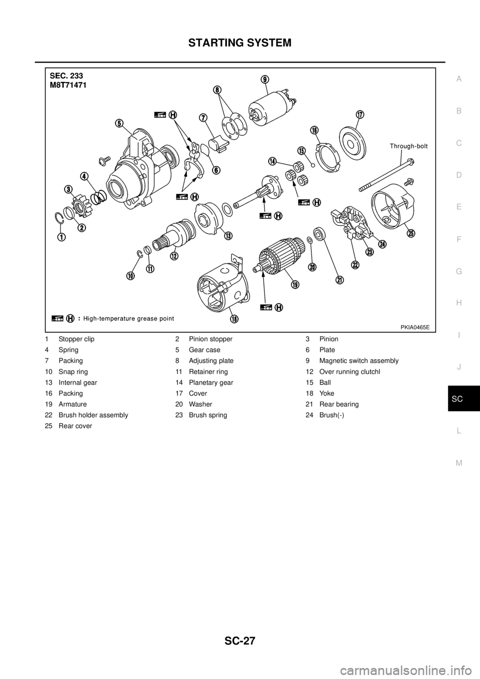
1 Stopper clip 2 Pinion stopper 3 Pinion
4 Spring 5 Gear case 6 Plate
7 Packing 8 Adjusting plate 9 Magnetic switch assembly
10 Snap ring 11 Retainer ring 12 Over running clutchl
13 Internal gear 14 Planetary gear 15 Ball
16 Packing 17 Cover 18 Yoke
19 Armature 20 Washer 21 Rear bearing
22 Brush holder assembly 23 Brush spring 24 Brush(-)
25 Rear cover
PKIA0465E
Page 2900 of 3066
SC-28
STARTING SYSTEM
Inspection
EKS0031L
MAGNETIC SWITCH CHECK
lBefore starting to check, disconnect battery ground cable.
lDisconnect “M” terminal of starter motor.
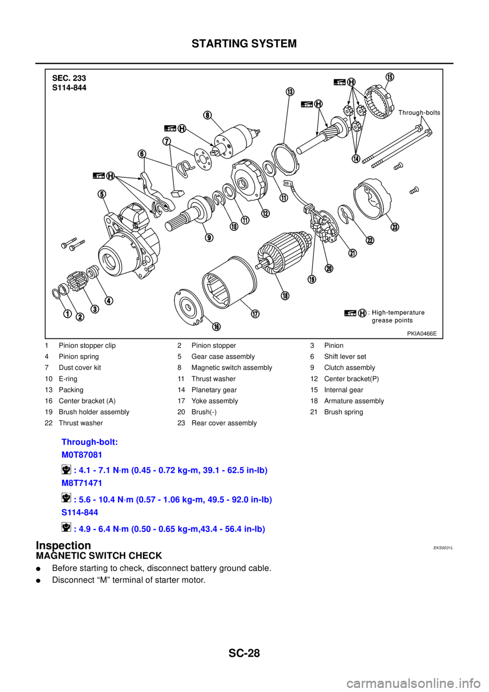
1 Pinion stopper clip 2 Pinion stopper 3 Pinion
4 Pinion spring 5 Gear case assembly 6 Shift lever set
7 Dust cover kit 8 Magnetic switch assembly 9 Clutch assembly
10 E-ring 11 Thrust washer 12 Center bracket(P)
13 Packing 14 Planetary gear 15 Internal gear
16 Center bracket (A) 17 Yoke assembly 18 Armature assembly
19 Brush holder assembly 20 Brush(-) 21 Brush spring
22 Thrust washer 23 Rear cover assembly
Through-bolt:
M0T87081
: 4.1 - 7.1 N·m (0.45 - 0.72 kg-m, 39.1 - 62.5 in-lb)
M8T71471
: 5.6 - 10.4 N·m (0.57 - 1.06 kg-m, 49.5 - 92.0 in-lb)
S114-844
: 4.9 - 6.4 N·m (0.50 - 0.65 kg-m,43.4 - 56.4 in-lb)
PKIA0466E
Trending: air filter, brake, headlamp, radio antenna, oil temperature, air bleeding, CD player
