NISSAN X-TRAIL 2003 Electronic Repair Manual
Manufacturer: NISSAN, Model Year: 2003, Model line: X-TRAIL, Model: NISSAN X-TRAIL 2003Pages: 3066, PDF Size: 51.47 MB
Page 781 of 3066
POWER DOOR LOCK — SUPER LOCK —
BL-37
C
D
E
F
G
H
J
K
L
MA
B
BL
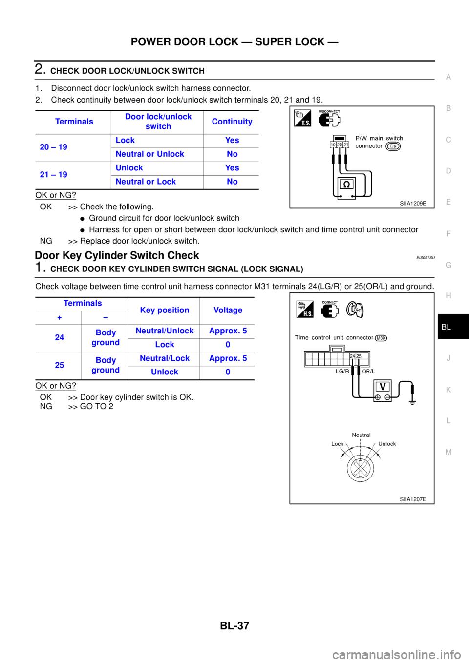
2.CHECK DOOR LOCK/UNLOCK SWITCH
1. Disconnect door lock/unlock switch harness connector.
2. Check continuity between door lock/unlock switch terminals 20, 21 and 19.
OK or NG?
OK >> Check the following.
lGround circuit for door lock/unlock switch
lHarness for open or short between door lock/unlock switch and time control unit connector
NG >> Replace door lock/unlock switch.
Door Key Cylinder Switch CheckEIS001SU
1.CHECK DOOR KEY CYLINDER SWITCH SIGNAL (LOCK SIGNAL)
Check voltage between time control unit harness connector M31 terminals 24(LG/R) or 25(OR/L) and ground.
OK or NG?
OK >> Door key cylinder switch is OK.
NG >> GO TO 2Te r m i n a l sDoor lock/unlock
switchContinuity
20 – 19Lock Yes
Neutral or Unlock No
21 – 19Unlock Yes
Neutral or Lock No
SIIA1209E
Te r m i na l s
Key position Voltage
+–
24Body
groundNeutral/Unlock Approx. 5
Lock 0
25Body
groundNeutral/Lock Approx. 5
Unlock 0
SIIA1207E
Page 782 of 3066
BL-38
POWER DOOR LOCK — SUPER LOCK —
2.CHECK DOOR KEY CYLINDER SWITCH
1. Disconnect door key cylinder switch harness connector.
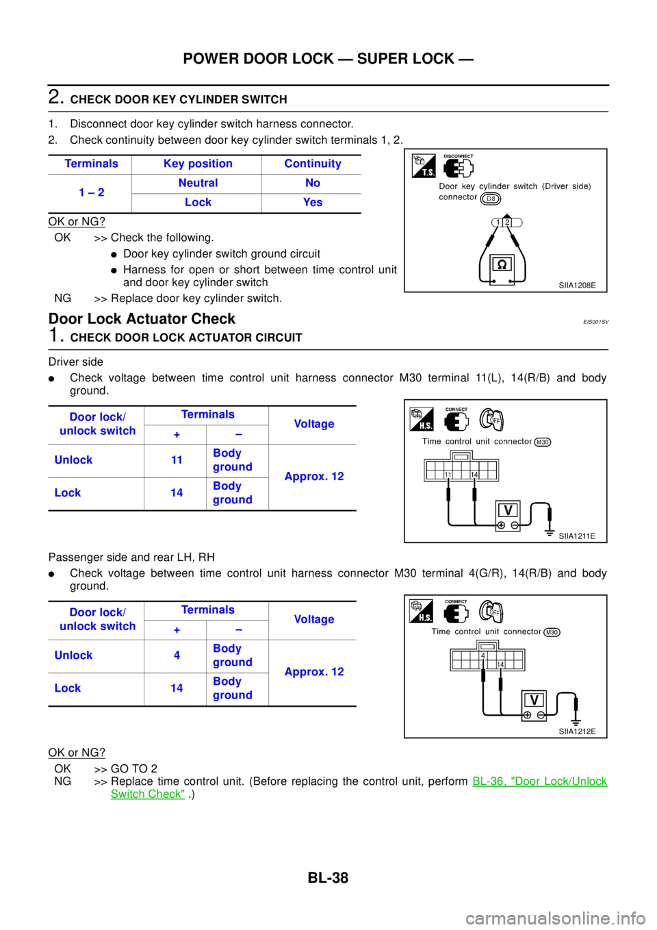
2. Check continuity between door key cylinder switch terminals 1, 2.
OK or NG?
OK >> Check the following.
lDoor key cylinder switch ground circuit
lHarness for open or short between time control unit
and door key cylinder switch
NG >> Replace door key cylinder switch.
Door Lock Actuator CheckEIS001SV
1.CHECK DOOR LOCK ACTUATOR CIRCUIT
Driver side
lCheck voltage between time control unit harness connector M30 terminal 11(L), 14(R/B) and body
ground.
Passenger side and rear LH, RH
lCheck voltage between time control unit harness connector M30 terminal 4(G/R), 14(R/B) and body
ground.
OK or NG?
OK >> GO TO 2
NG >> Replace time control unit. (Before replacing the control unit, performBL-36, "
Door Lock/Unlock
Switch Check".) Terminals Key position Continuity
1–2Neutral No
Lock Yes
SIIA1208E
Door lock/
unlock switchTe r m i n a l s
Vo l ta g e
+–
Unlock 11Body
ground
Approx. 12
Lock 14Body
ground
SIIA1211E
Door lock/
unlock switchTe r m i n a l s
Vo l ta g e
+–
Unlock 4Body
ground
Approx. 12
Lock 14Body
ground
SIIA1212E
Page 783 of 3066
POWER DOOR LOCK — SUPER LOCK —
BL-39
C
D
E
F
G
H
J
K
L
MA
B
BL
2.CHECK DOOR LOCK ACTUATOR
1. Disconnect door lock actuator harness connector.
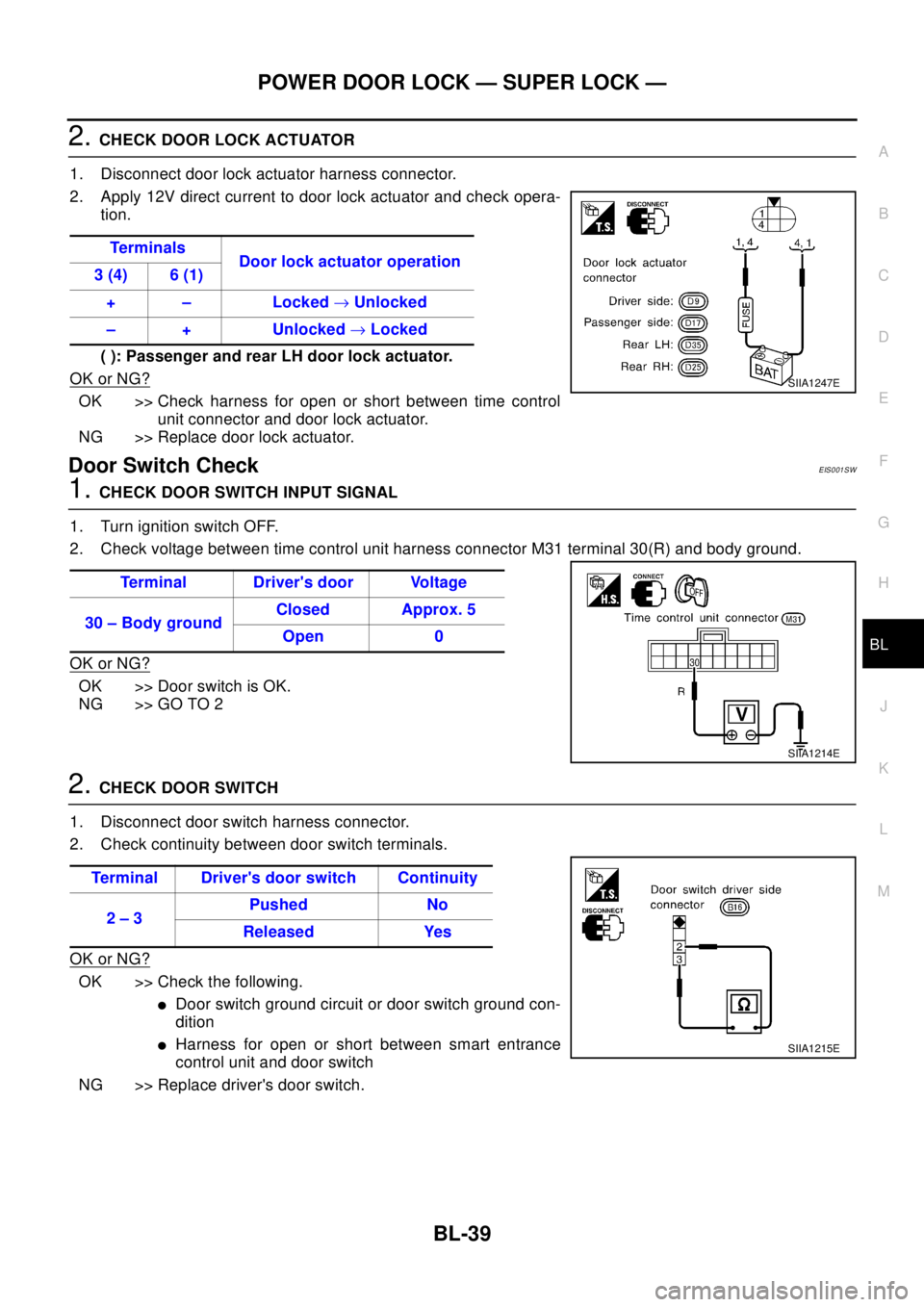
2. Apply 12V direct current to door lock actuator and check opera-
tion.
( ): Passenger and rear LH door lock actuator.
OK or NG?
OK >> Check harness for open or short between time control
unit connector and door lock actuator.
NG >> Replace door lock actuator.
Door Switch CheckEIS001SW
1.CHECK DOOR SWITCH INPUT SIGNAL
1. Turn ignition switch OFF.
2. Check voltage between time control unit harness connector M31 terminal 30(R) and body ground.
OK or NG?
OK >> Door switch is OK.
NG >> GO TO 2
2.CHECK DOOR SWITCH
1. Disconnect door switch harness connector.
2. Check continuity between door switch terminals.
OK or NG?
OK >> Check the following.
lDoor switch ground circuit or door switch ground con-
dition
lHarness for open or short between smart entrance
control unit and door switch
NG >> Replace driver's door switch.Te r m i n a l s
Door lock actuator operation
3 (4) 6 (1)
+ – Locked®Unlocked
– + Unlocked®Locked
SIIA1247E
Terminal Driver's door Voltage
30–BodygroundClosed Approx. 5
Open 0
SIIA1214E
Terminal Driver's door switch Continuity
2–3Pushed No
Released Yes
SIIA1215E
Page 784 of 3066
BL-40
POWER DOOR LOCK — SUPER LOCK —
Door Unlock Sensor Check
EIS001SX
1.CHECK DRIVER DOOR UNLOCK SENSOR INPUT SIGNAL
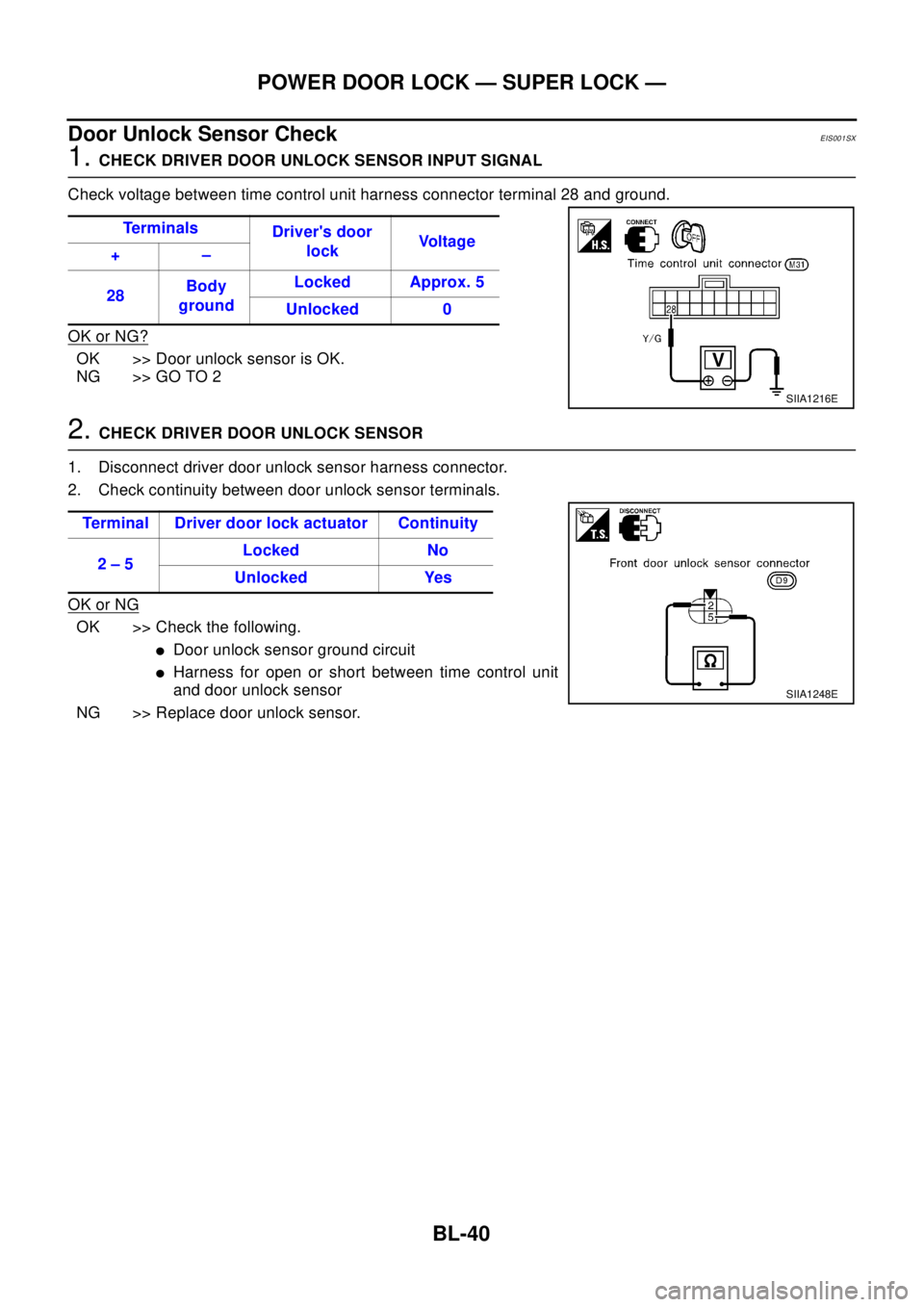
Check voltage between time control unit harness connector terminal 28 and ground.
OK or NG?
OK >> Door unlock sensor is OK.
NG >> GO TO 2
2.CHECK DRIVER DOOR UNLOCK SENSOR
1. Disconnect driver door unlock sensor harness connector.
2. Check continuity between door unlock sensor terminals.
OK or NG
OK >> Check the following.
lDoor unlock sensor ground circuit
lHarness for open or short between time control unit
and door unlock sensor
NG >> Replace door unlock sensor.Te r m i n a l s
Driver's door
lockVo l t a g e
+–
28Body
groundLocked Approx. 5
Unlocked 0
SIIA1216E
Terminal Driver door lock actuator Continuity
2–5Locked No
Unlocked Yes
SIIA1248E
Page 785 of 3066
POWER DOOR LOCK — SUPER LOCK —
BL-41
C
D
E
F
G
H
J
K
L
MA
B
BL
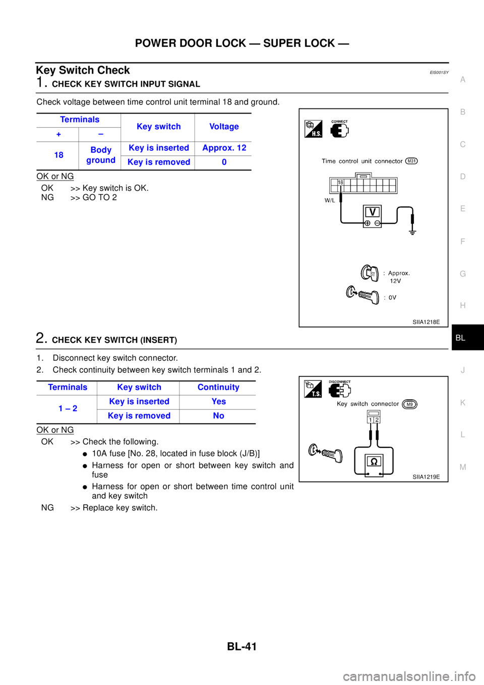
Key Switch CheckEIS001SY
1.CHECK KEY SWITCH INPUT SIGNAL
Check voltage between time control unit terminal 18 and ground.
OK or NG
OK >>KeyswitchisOK.
NG >> GO TO 2
2.CHECK KEY SWITCH (INSERT)
1. Disconnect key switch connector.
2. Check continuity between key switch terminals 1 and 2.
OK or NG
OK >> Check the following.
l10A fuse [No. 28, located in fuse block (J/B)]
lHarness for open or short between key switch and
fuse
lHarness for open or short between time control unit
and key switch
NG >> Replace key switch.Te r m i n a l s
Key switch Voltage
+–
18Body
groundKey is inserted Approx. 12
Key is removed 0
SIIA1218E
Terminals Key switch Continuity
1–2Keyisinserted Yes
Keyisremoved No
SIIA1219E
Page 786 of 3066
BL-42
POWER DOOR LOCK — SUPER LOCK —
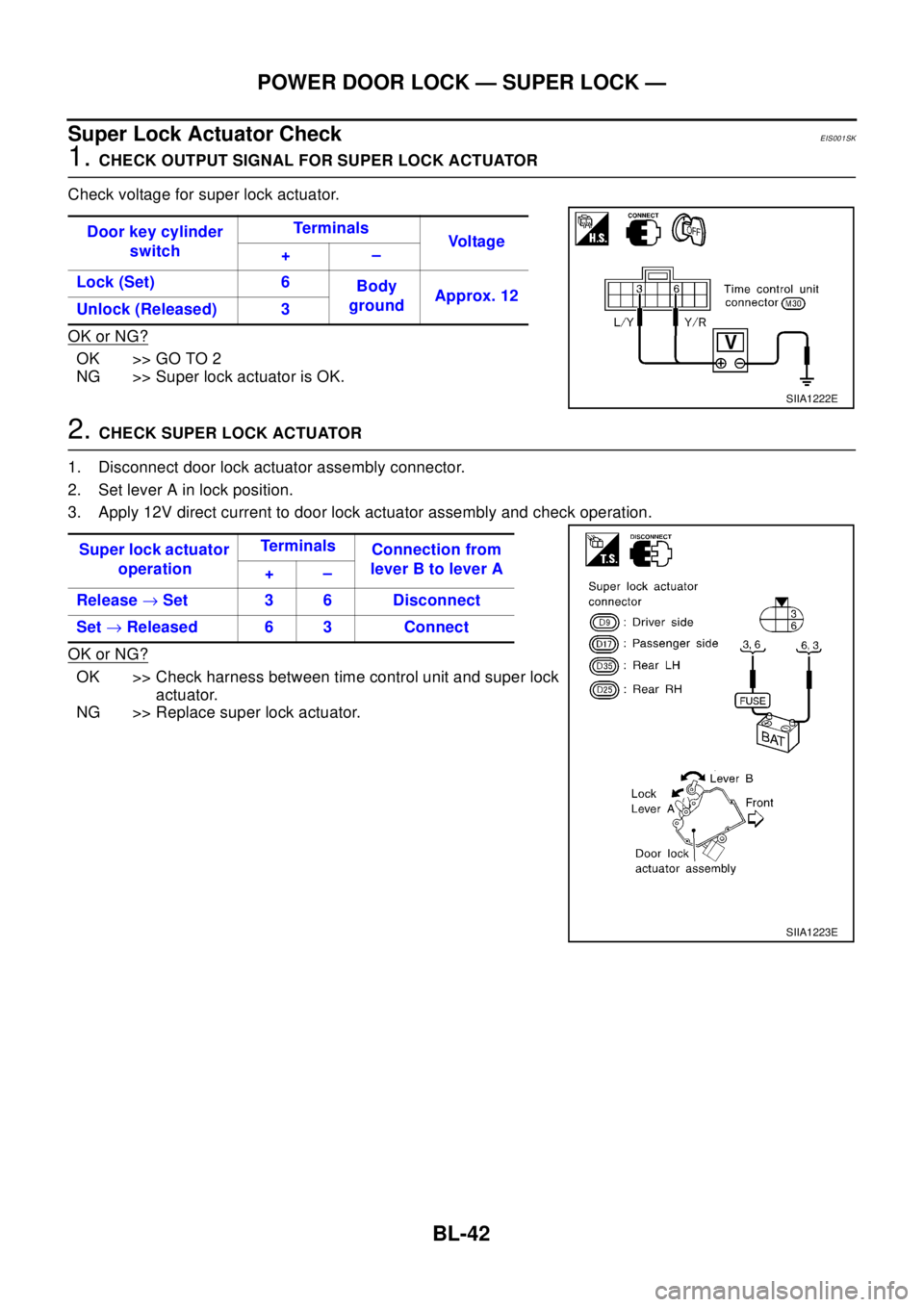
Super Lock Actuator Check
EIS001SK
1.CHECK OUTPUT SIGNAL FOR SUPER LOCK ACTUATOR
Check voltage for super lock actuator.
OK or NG?
OK >> GO TO 2
NG >> Super lock actuator is OK.
2.CHECK SUPER LOCK ACTUATOR
1. Disconnect door lock actuator assembly connector.
2. Set lever A in lock position.
3. Apply 12V direct current to door lock actuator assembly and check operation.
OK or NG?
OK >> Check harness between time control unit and super lock
actuator.
NG >> Replace super lock actuator.Door key cylinder
switchTe r m i n a l s
Vo l ta g e
+–
Lock (Set) 6
Body
groundApprox. 12
Unlock (Released) 3
SIIA1222E
Super lock actuator
operationTe r m i n a l s
Connection from
lever B to lever A
+–
Release®Set 3 6 Disconnect
Set®Released 6 3 Connect
SIIA1223E
Page 787 of 3066
POWER DOOR LOCK — SUPER LOCK —
BL-43
C
D
E
F
G
H
J
K
L
MA
B
BL
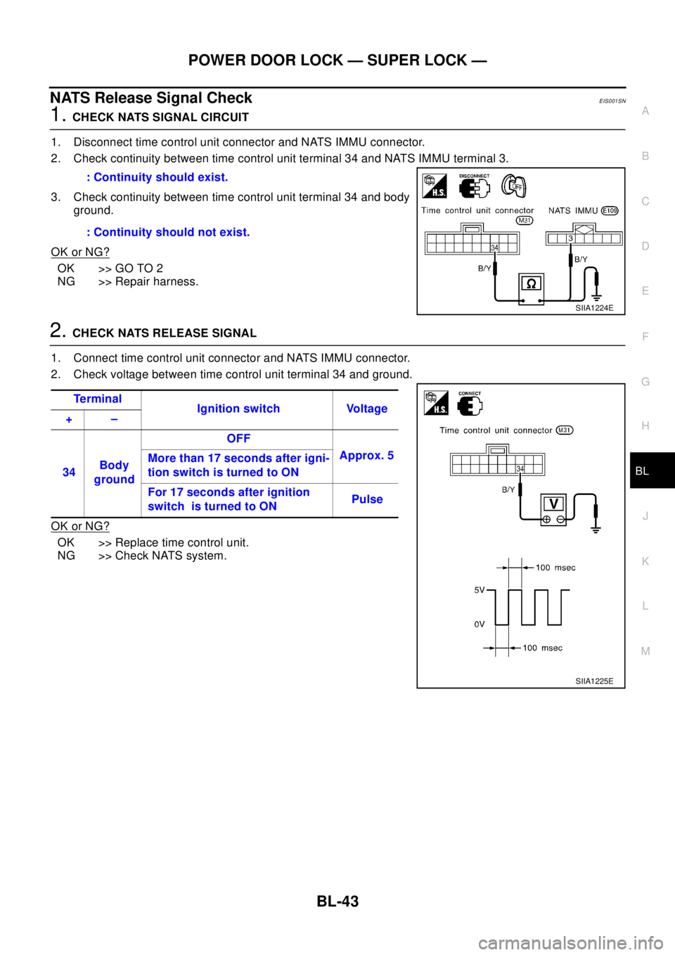
NATS Release Signal CheckEIS001SN
1.CHECK NATS SIGNAL CIRCUIT
1. Disconnect time control unit connector and NATS IMMU connector.
2. Check continuity between time control unit terminal 34 and NATS IMMU terminal 3.
3. Check continuity between time control unit terminal 34 and body
ground.
OK or NG?
OK >> GO TO 2
NG >> Repair harness.
2.CHECK NATS RELEASE SIGNAL
1. Connect time control unit connector and NATS IMMU connector.
2. Check voltage between time control unit terminal 34 and ground.
OK or NG?
OK >> Replace time control unit.
NG >> Check NATS system.: Continuity should exist.
: Continuity should not exist.
SIIA1224E
Te r m i n a l
Ignition switch Voltage
+–
34Body
groundOFF
Approx. 5
More than 17 seconds after igni-
tion switch is turned to ON
For 17 seconds after ignition
switch is turned to ONPulse
SIIA1225E
Page 788 of 3066
BL-44
POWER DOOR LOCK — SUPER LOCK —
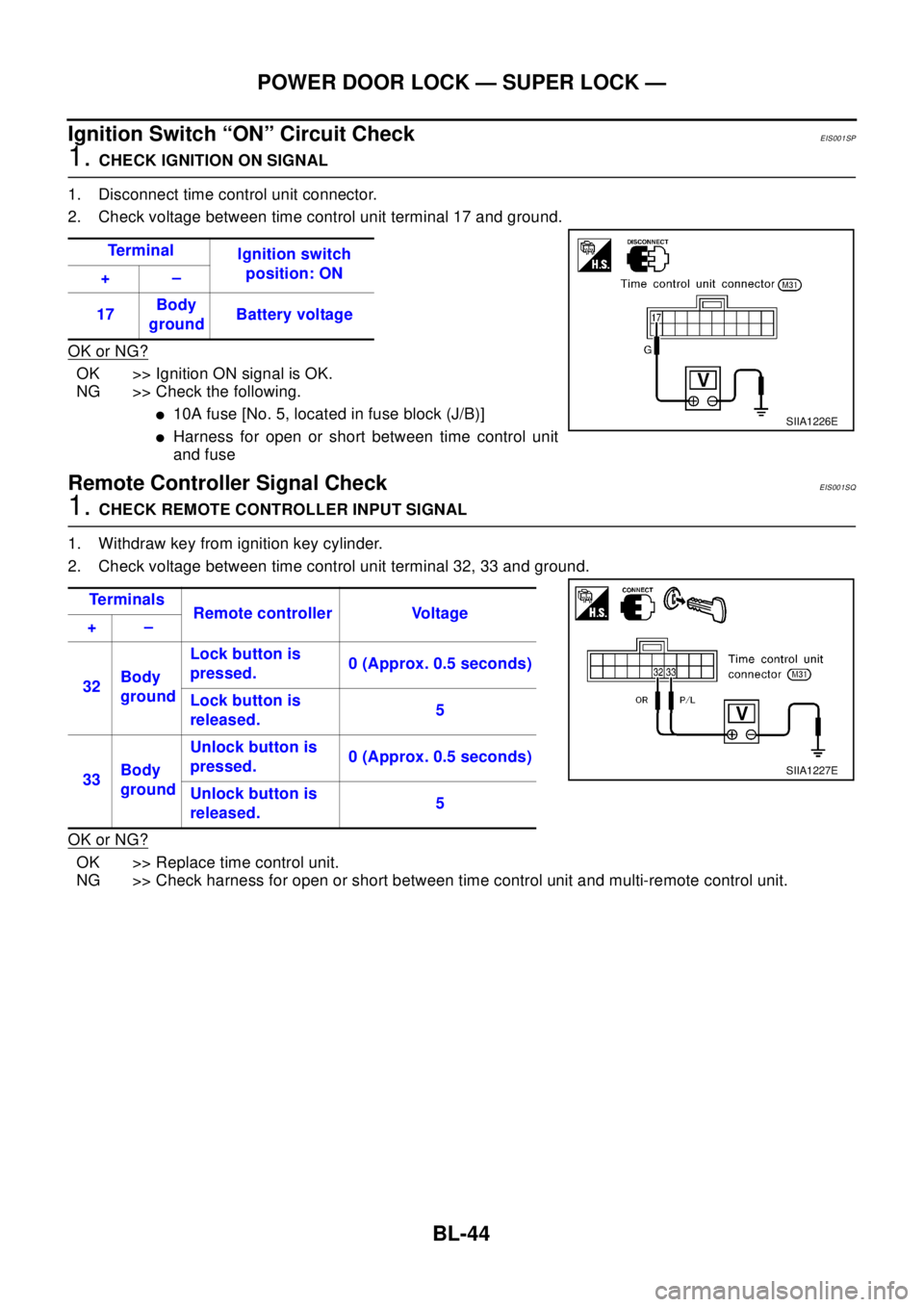
Ignition Switch “ON” Circuit Check
EIS001SP
1.CHECK IGNITION ON SIGNAL
1. Disconnect time control unit connector.
2. Check voltage between time control unit terminal 17 and ground.
OK or NG?
OK >> Ignition ON signal is OK.
NG >> Check the following.
l10A fuse [No. 5, located in fuse block (J/B)]
lHarness for open or short between time control unit
and fuse
Remote Controller Signal CheckEIS001SQ
1.CHECK REMOTE CONTROLLER INPUT SIGNAL
1. Withdraw key from ignition key cylinder.
2. Check voltage between time control unit terminal 32, 33 and ground.
OK or NG?
OK >> Replace time control unit.
NG >> Check harness for open or short between time control unit and multi-remote control unit.Te r m i n a l
Ignition switch
position: ON
+–
17Body
groundBattery voltage
SIIA1226E
Te r m i n a l s
Remote controller Voltage
+–
32Body
groundLock button is
pressed.0 (Approx. 0.5 seconds)
Lock button is
released.5
33Body
groundUnlock button is
pressed.0 (Approx. 0.5 seconds)
Unlock button is
released.5
SIIA1227E
Page 789 of 3066
MULTI-REMOTE CONTROL SYSTEM
BL-45
C
D
E
F
G
H
J
K
L
MA
B
BL
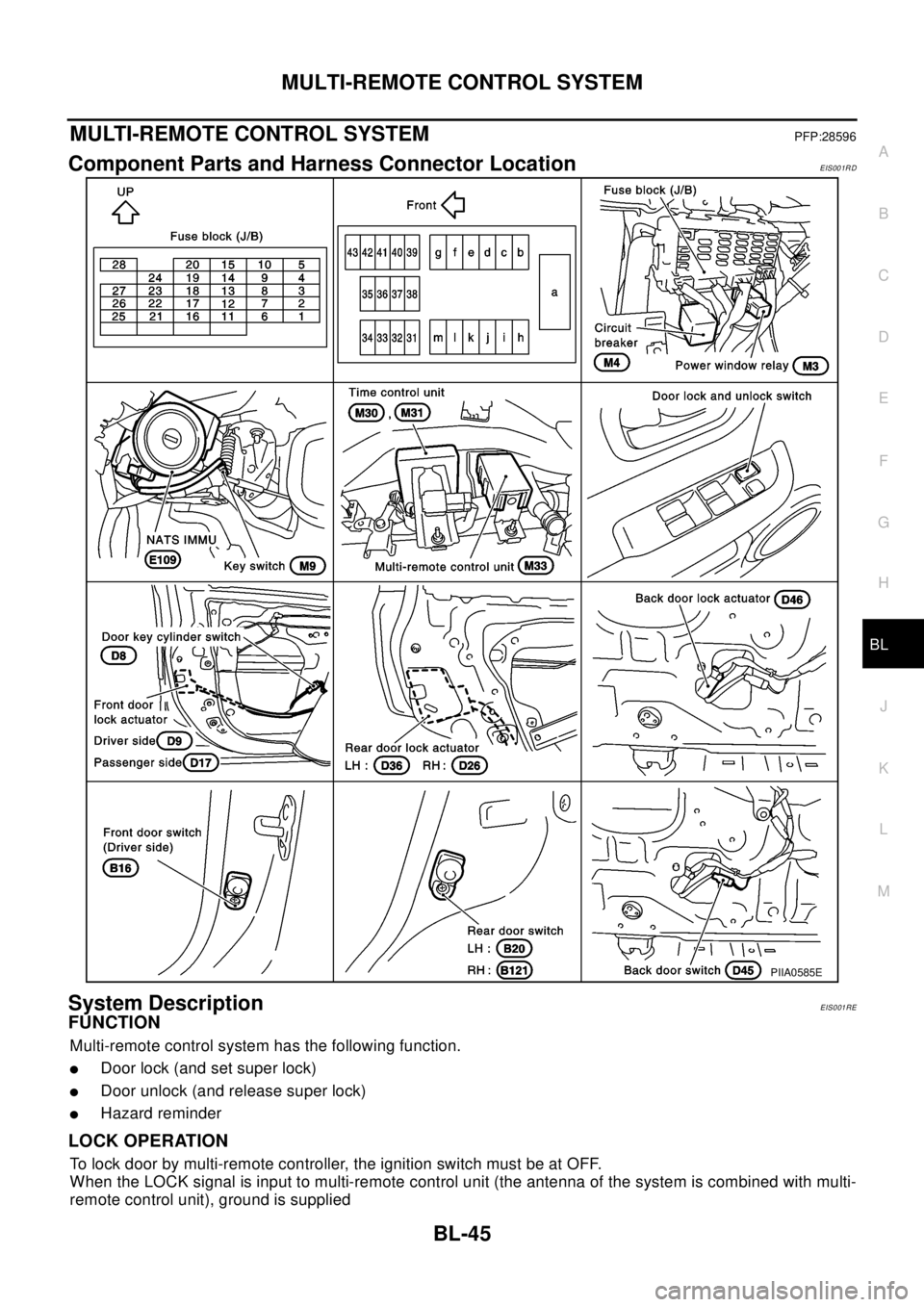
MULTI-REMOTE CONTROL SYSTEMPFP:28596
Component Parts and Harness Connector LocationEIS001RD
System DescriptionEIS001RE
FUNCTION
Multi-remote control system has the following function.
lDoor lock (and set super lock)
lDoor unlock (and release super lock)
lHazard reminder
LOCK OPERATION
To lock door by multi-remote controller, the ignition switch must be at OFF.
When the LOCK signal is input to multi-remote control unit (the antenna of the system is combined with multi-
remote control unit), ground is supplied
PIIA0585E
Page 790 of 3066

BL-46
MULTI-REMOTE CONTROL SYSTEM
lthrough multi-remote control unit terminal 5
lto time control unit terminal 32.
Then time control unit operates to lock doors and set super lock (models with super lock).
UNLOCK OPERATION
When the UNLOCK signal is input to multi-remote control unit (the antenna of the system is combined with
multi-remote control unit), ground is supplied
lthrough multi-remote control unit terminal 6
lto time control unit terminal 33.
Time control unit operates to unlock driver's door and release super lock (models with super lock).
Then, if an unlock signal is sent from the remote controller again within 5 seconds, all other doors will be
unlocked.
HAZARD REMINDER
When the doors are locked or unlocked by multi-remote controller (signal from driver side unlock sensor), sup-
ply power to hazard warning lamp flashes as follows
lLock operation: Flash once
lUnlock operation: Flash twice
MULTI-REMOTE CONTROLLER ID CODE ENTRY
A maximum of four remote controllers can be entered.
To enter ID code entry, the following signals must be input to the multi-remote control unit.
lIgnition switch (ON)
lSignal from remote controller
For detailed procedure, refer toBL-52, "
ID Code Entry Procedure".