OPEL GT-R 1973 Service Manual
Manufacturer: OPEL, Model Year: 1973, Model line: GT-R, Model: OPEL GT-R 1973Pages: 625, PDF Size: 17.22 MB
Page 281 of 625
5C- 221973 OPEL SERVICE MANUAL
DRUM BRAKES
CONTENTS
Subject
DESCRIPTION AND OPERATION:
Description of Brake Mechanism. . . . . . . . . . . . . . . . . . . . . . . . . . . . . . .OperationofHydraulicServiceBrake
. . . . . . . . . . . . . . . . . . . . . . . .DIAGNOSIS:
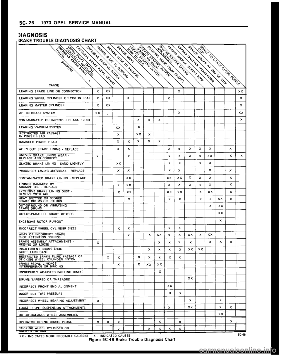
BrakeTrouble
Diagnosis. . . . . . . . . . . . . . . . . . . . . . . . . . . . . . . . . . . . . . . . . . . . . . . . . .MAINTENANCE AND ADJUSTMENTS:
BrakeAdjustment
. . . . . . . . . . . . . . . . . . . . . . . . . . . . . . . . . . . . . . . . . . . . . . . . . . . . . . . . . . . . . .Filling, Bleeding and Flushing Brake
Hydraulic System
. . . . . . . . . . . . . . . . . . . . . . . . . . . . . . . . . . . . . . . . . . . . . . . . . . . . . . . . . .MAJOR REPAIR:
Replace or Reline Brake Shoes
. . . . . . . . . . . . . . . . . . . . . . . . . . . . . . . . . . .Inspecting and Reconditioning Brake Drums
. . . . . . . . . .Brake Wheel Cylinder Overhaul
. . . . . . . . . . . . . . . . . . . . . . . . . . . . . . . . . .
ReplacingBrakePipes. . . . . . . . . . . . . . . . . . . . . . . . . . . . . . . . . . . . . . . . . . . . . . . . . . . . . .SPECIFICATIONS:
Brake Specifications
. . . . . . . . . . , . . . . . . . . . . . . . . . . . . . . . . . . . . . . . . . . . . . . . . . . . . . . .
DESCRIPTION AND OPERATION - DRUM
BRAKES
DESCRIPTION OF BRAKE MECHANISM
Wheel Brake Assemblies
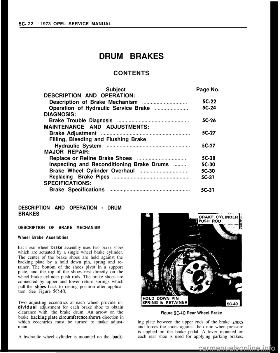
Each rear wheel brake assembly uses two brake shoeswhich are actuated by a single wheel brake cylinder.
The center of the brake shoes are held against the
backing plate by a hold down pin, spring and re-
tainer. The bottom of the shoes pivot in a support
plate, and the top of the shoes rest directly on the
wheel brake cylinder push rods. The brake shoes are
connected by upper and lower return springs which
pull the sh6es back to resting position after applica-
tion. See Figure
5C-40.Two adjusting eccentrics at each wheel provide in-
dividual adjustment for each brake shoe to obtain
clearance with. the brake drum. An arrow on the
brake backing.plate circumference,shows direction in
which eccentrics must be turned to make adjust-
ment.
A hydraulic wheel cylinder is mounted on the back-Page No.5C-225C-245C-26
5C-275C-275C-28
5c-30
5c-305c-315c-31
Figure 5C-40 Rear Wheel Brake
ing plate between the upper ends of the brake
shoeand forces the shoes against the drum when pressure
is applied on the brake pedal. A lever mounted on
each rear shoe is used for applying parking brakes.
Page 282 of 625
DRUM BRAKES5C- 23
Parking Brake Control System
The hand-operated parking brake lever is mounted
between the front seats on the propeller shaft tunnel.
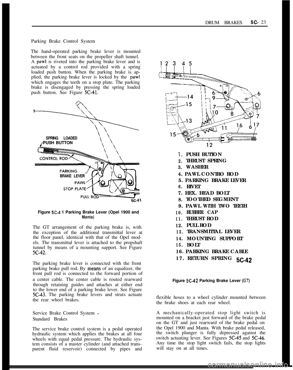
A paw1 is riveted into the parking brake lever and is
actuated by a control rod provided with a spring
loaded push button. When the parking brake is ap-
plied, the parking brake lever is locked by the
paw1which engages the teeth on a stop plate. The parking
brake is disengaged by pressing the spring loaded
push button. See Figure
5C-41.
SPRING LOADED,-PUSH BUTTON
BRAKE LEVER
s\., \\,Figure
5C-4 1 Parking Brake Lever (Opel 1900 and
Manta)The GT arrangement of the parking brake is, with
the exception of the additional transmittal lever at
the floor panel, identical with that of the Opel mod-
els. The transmittal lever is attached to the propshaft
tunnel by means of a mounting support. See Figure
5C-42.The parking brake lever is connected with the front
parking brake pull rod. By means of an equalizer, the
front pull rod is connected to the forward portion of
a center cable. The center cable is routed rearward
through retaining guides and attaches at either end
to the lower end of a parking brake lever. See Figure
5C-43. The parking brake levers and struts actuate
the rear wheel brakes.
Service Brake Control System
-Standard Brakes
The service brake control system is a pedal operated
hydraulic system which applies the brakes at all four
wheels with equal pedal pressure. The hydraulic sys-
tem consists of a master cylinder (and attached trans-
parent fluid reservoir) connected by pipes and
1.PUSH BUTTON
2.THRUST SPRING
3.WASHER
4. PAWL CONTRO ROD
5. PARKING BRAKE LEVER
6.RIVET
7. HEX. HEAD BOLT
8.TOOTHED SEGMENT
9. PAWL WITH TWO TEETH
10.RUBBER CAP
11.THRUST ROD
12.PULL ROD
13.TRANSMITTAL LEVER
14.MOUNTING SUPPORT
15.BOLT
16. PARKING BRAKE CABLE
17. RETURN SPRING
sea2Figure 5C-42 Parking Brake Lever
(GT)flexible hoses to a wheel cylinder mounted between
the brake shoes at each rear wheel.
A mechanically-operated stop light switch is
mounted on a bracket just forward of the brake pedal
on the GT and just rearward of the brake pedal on
the Opel 1900 and Manta. With brake pedal released,
the switch plunger is fully depressed against the
switch actuating lever. See Figures
5C-45 and 5C-46.Any time the stop light switch fails, the stop lights
will stay on at all times.
Page 283 of 625
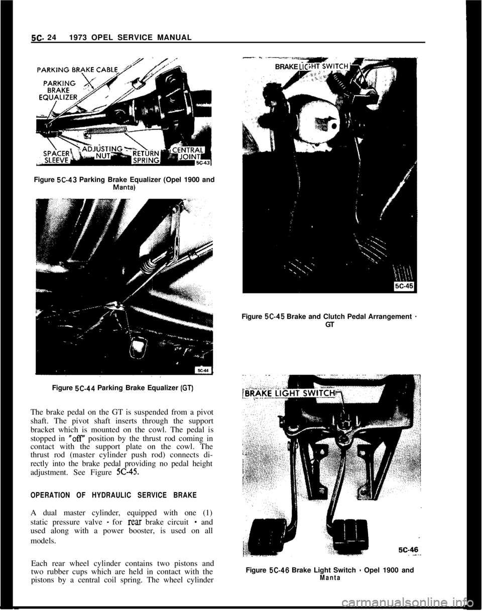
5C- 241973 OPEL SERVICE MANUAL-~ - -----*““YBRAKE LICFigure 5C-43 Parking Brake Equalizer (Opel 1900 and
Mallta)Figure 5C-45 Brake and Clutch Pedal Arrangement
-GT
Figure 5C-44 Parking Brake Equalizer
(GT)The brake pedal on the GT is suspended from a pivot
shaft. The pivot shaft inserts through the support
bracket which is mounted on the cowl. The pedal is
stopped in
“off position by the thrust rod coming in
contact with the support plate on the cowl. The
thrust rod (master cylinder push rod) connects di-
rectly into the brake pedal providing no pedal height
adjustment. See Figure
5C-45.
OPERATION OF HYDRAULIC SERVICE BRAKEA dual master cylinder, equipped with one (1)
static pressure valve
- for rear brake circuit - and
used along with a power booster, is used on all
models.
Each rear wheel cylinder contains two pistons and
two rubber cups which are held in contact with the
pistons by a central coil spring. The wheel cylinderFigure 5C-46 Brake Light Switch
- Opel 1900 andManta
Page 284 of 625
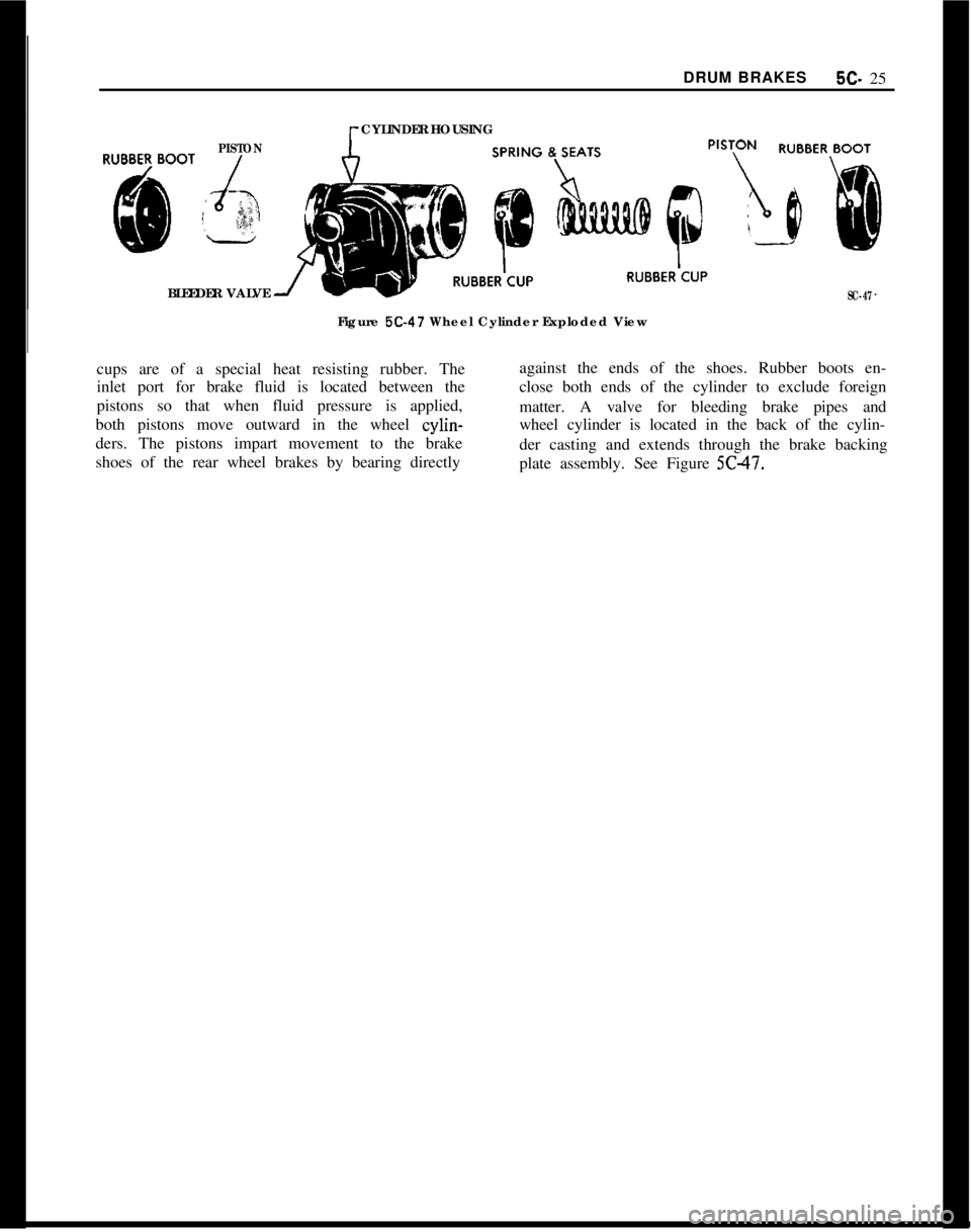
DRUM BRAKES5C- 25PISTONCYLINDER HOUSING
BLEEDER VALVE
SC-47Figure
5C-47 Wheel Cylinder Exploded View
cups are of a special heat resisting rubber. Theagainst the ends of the shoes. Rubber boots en-
inlet port for brake fluid is located between theclose both ends of the cylinder to exclude foreign
pistons so that when fluid pressure is applied,
matter. A valve for bleeding brake pipes and
both pistons move outward in the wheel cylin-wheel cylinder is located in the back of the cylin-
ders. The pistons impart movement to the brake
der casting and extends through the brake backing
shoes of the rear wheel brakes by bearing directly
plate assembly. See Figure 5C47.
Page 285 of 625
5C- 261973 OPEL SERVICE MANUAL
Page 286 of 625
DRUM BRAKES5C- 27MAINTENANCE AND ADJUSTMENTSBRAKE ADJUSTMENT
Preliminary Checks
1. Depress brake pedal firmly. If pedal travels to
within two inches of toeboard and has a hard feel,
brake shoes require adjustment or relining. However,
if pedal has a spongy feel, brake system needs bleed-
ing.2. Remove one rear drum if lining is worn nearly to
rivets. Reline both rear brakes (drum brakes only).
3. Check fluid level in master cylinder reservoir and
add fluid if necessary.
4. Fully release parking brake lever and place trans-
mission in neutral.
5. Pull on both ends of rear brake cable a number of
times to make sure that cables operate rear brake
shoes freely and do not bind in conduits. Check for
free movement of cable in brake cable sheave and
check brake cable spring for tension. Replace a weak
or broken cable spring.
Pedal Height Adjustment
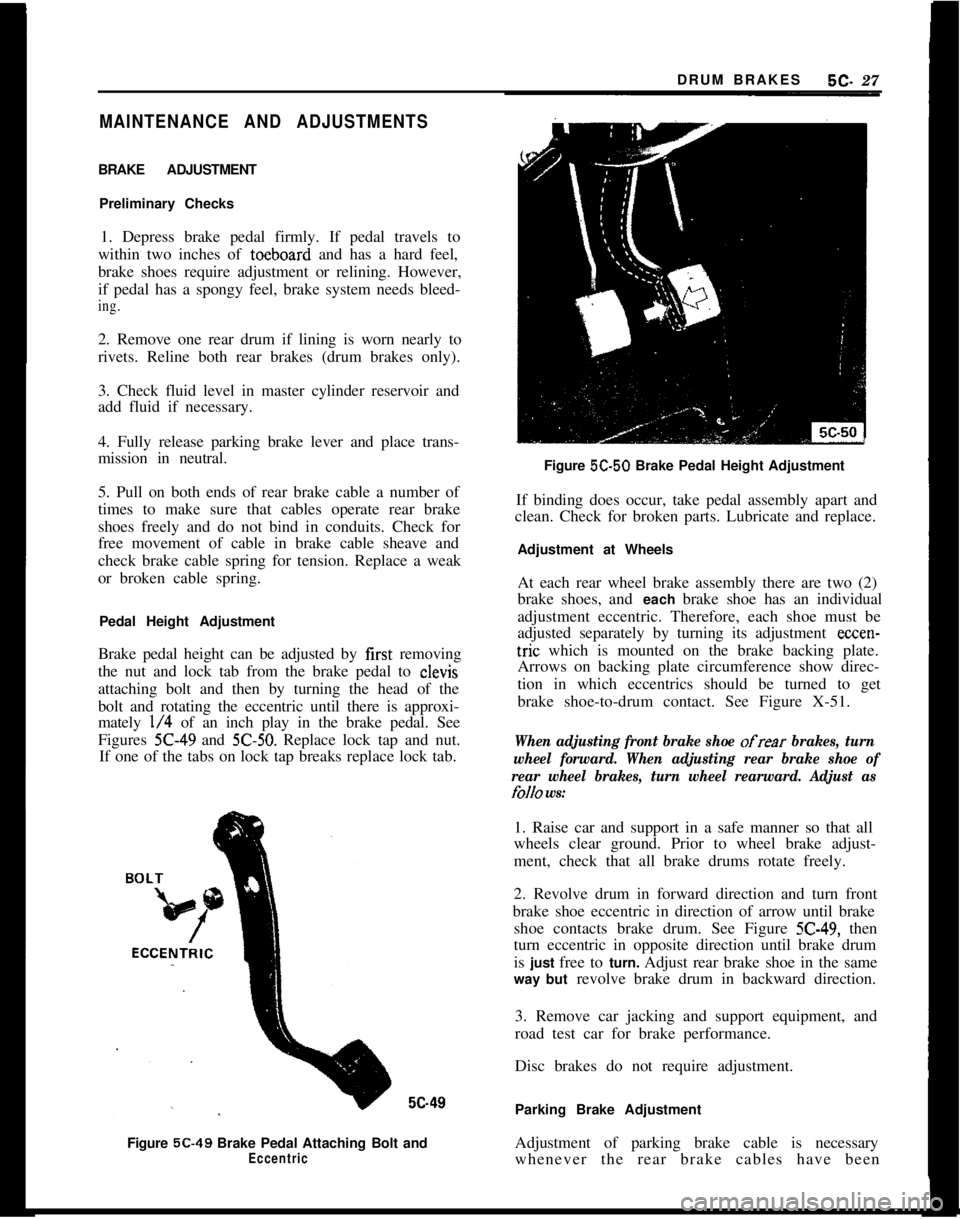
Brake pedal height can be adjusted by first removing
the nut and lock tab from the brake pedal to clevis
attaching bolt and then by turning the head of the
bolt and rotating the eccentric until there is approxi-
mately
l/4 of an inch play in the brake pedal. See
Figures
X-49 and 5C-50. Replace lock tap and nut.
If one of the tabs on lock tap breaks replace lock tab.5c49
Figure 5C-49 Brake Pedal Attaching Bolt and
EccentricFigure 5C-50 Brake Pedal Height Adjustment
If binding does occur, take pedal assembly apart and
clean. Check for broken parts. Lubricate and replace.
Adjustment at Wheels
At each rear wheel brake assembly there are two (2)
brake shoes, and each brake shoe has an individual
adjustment eccentric. Therefore, each shoe must be
adjusted separately by turning its adjustment
ccccn-tric which is mounted on the brake backing plate.
Arrows on backing plate circumference show direc-
tion in which eccentrics should be turned to get
brake shoe-to-drum contact. See Figure X-51.
When adjusting front brake shoe ofrear brakes, turn
wheel forward. When adjusting rear brake shoe of
rear wheel brakes, turn wheel rearward. Adjust as
folio ws:1. Raise car and support in a safe manner so that all
wheels clear ground. Prior to wheel brake adjust-
ment, check that all brake drums rotate freely.
2. Revolve drum in forward direction and turn front
brake shoe eccentric in direction of arrow until brake
shoe contacts brake drum. See Figure
5C-49, then
turn eccentric in opposite direction until brake drum
is just free to turn. Adjust rear brake shoe in the same
way but revolve brake drum in backward direction.
3. Remove car jacking and support equipment, and
road test car for brake performance.
Disc brakes do not require adjustment.
Parking Brake Adjustment
Adjustment of parking brake cable is necessary
whenever the rear brake cables have been
Page 287 of 625
5C- 281973 OPEL SERVICE MANUAL
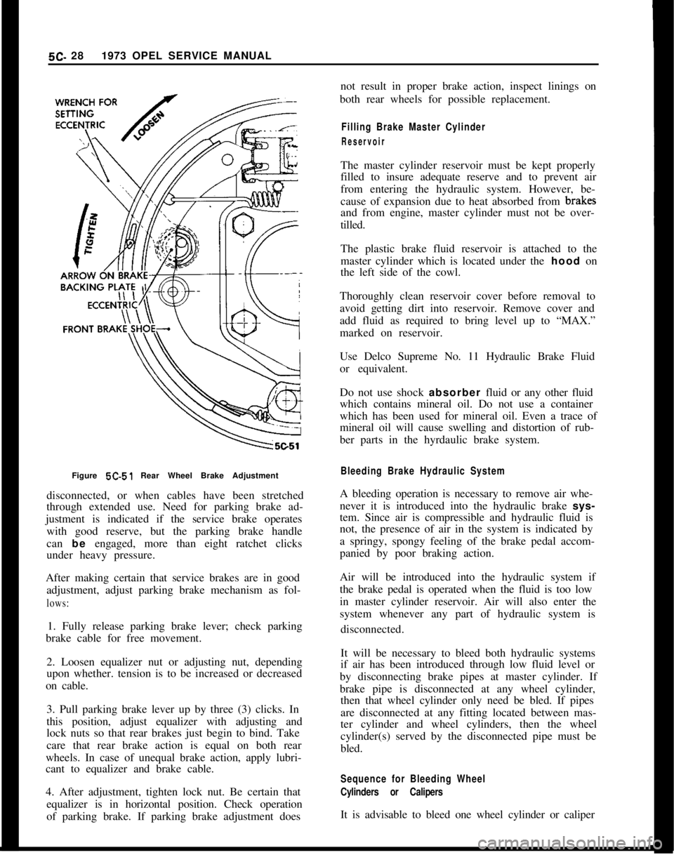
Figure 5C-51 Rear Wheel Brake Adjustment
disconnected, or when cables have been stretched
through extended use. Need for parking brake ad-
justment is indicated if the service brake operates
with good reserve, but the parking brake handle
can be engaged, more than eight ratchet clicks
under heavy pressure.
After making certain that service brakes are in good
adjustment, adjust parking brake mechanism as fol-lows:1. Fully release parking brake lever; check parking
brake cable for free movement.
2. Loosen equalizer nut or adjusting nut, depending
upon whether. tension is to be increased or decreased
on cable.
3. Pull parking brake lever up by three (3) clicks. In
this position, adjust equalizer with adjusting and
lock nuts so that rear brakes just begin to bind. Take
care that rear brake action is equal on both rear
wheels. In case of unequal brake action, apply lubri-
cant to equalizer and brake cable.
4. After adjustment, tighten lock nut. Be certain that
equalizer is in horizontal position. Check operation
of parking brake. If parking brake adjustment doesnot result in proper brake action, inspect linings on
both rear wheels for possible replacement.
Filling Brake Master Cylinder
ReservoirThe master cylinder reservoir must be kept properly
filled to insure adequate reserve and to prevent air
from entering the hydraulic system. However, be-
cause of expansion due to heat absorbed from brakff
and from engine, master cylinder must not be over-
tilled.
The plastic brake fluid reservoir is attached to the
master cylinder which is located under the hood on
the left side of the cowl.
Thoroughly clean reservoir cover before removal to
avoid getting dirt into reservoir. Remove cover and
add fluid as required to bring level up to “MAX.”
marked on reservoir.
Use Delco Supreme No. 11 Hydraulic Brake Fluid
or equivalent.
Do not use shock absorber fluid or any other fluid
which contains mineral oil. Do not use a container
which has been used for mineral oil. Even a trace of
mineral oil will cause swelling and distortion of rub-
ber parts in the hyrdaulic brake system.
Bleeding Brake Hydraulic SystemA bleeding operation is necessary to remove air whe-
never it is introduced into the hydraulic brake sys-
tem. Since air is compressible and hydraulic fluid is
not, the presence of air in the system is indicated by
a springy, spongy feeling of the brake pedal accom-
panied by poor braking action.
Air will be introduced into the hydraulic system if
the brake pedal is operated when the fluid is too low
in master cylinder reservoir. Air will also enter the
system whenever any part of hydraulic system is
disconnected.
It will be necessary to bleed both hydraulic systems
if air has been introduced through low fluid level or
by disconnecting brake pipes at master cylinder. If
brake pipe is disconnected at any wheel cylinder,
then that wheel cylinder only need be bled. If pipes
are disconnected at any fitting located between mas-
ter cylinder and wheel cylinders, then the wheel
cylinder(s) served by the disconnected pipe must be
bled.
Sequence for Bleeding Wheel
Cylinders or CalipersIt is advisable to bleed one wheel cylinder or caliper
Page 288 of 625
DRUM BRAKESBC- 29
at a time to avoid getting fluid level in reservoir
dangerously low. The correct sequence for bleeding
is bleed the wheel cylinder or caliper nearest the
master cylinder first in either circuit.
Do not perform bleeding operation while any brake
drum is removed.
Bleeding Wheel Cylinder or Caliper
1. Check fluid level, in reservoir and refill, if neces-
sary. Level must be brought up to “MAX” mark on
plastic reservoir.
2. Clean all dirt from around respective bleeder
valve, and then remove cap.
3. Push bleeder hose over bleeder valve, placing
other end of hose in a glass jar. Bleeder hose should
always be used to avoid getting fluid on linings.
4. Hold pressure on brake pedal and crack open the
bleeder valve to allow air (and,or) brake fluid to flow
out of the system. Allow pedal to travel to the floor.
Close bleeder valve. Release pedal and repeat this
procedure at each wheel cylinder in the circuit until
all air is removed. Frequently check reservoir fluid
level. Allowing fluid to be emptied will draw air into
the system.
5. Remove bleeder hose and install cap.
6. When bleeding operation is completed, make sure
that fluid level is brought up to “MAX” marking on
reservoir, then install cover.
7. Discard the brake fluid deposited in glass jar dur-
ing bleeding operation.
Flushing Brake Hydraulic System
It is recommended that both brake system circuits be
thoroughly flushed whenever the master cylinder is
replaced or if there is any doubt as to the grade of
fluid in the system.
Flushing of the brake system is performed in the
same manner as the bleeding operation except that
fluid is forced through the lines and wheel cylinder
until it emerges clear in color. Approximately one
half pint of brake fluid is required to flush the hy-
draulic system thoroughly.
When flushing is completed, make certain the master
cylinder reservoir is filled to the proper level.Figure
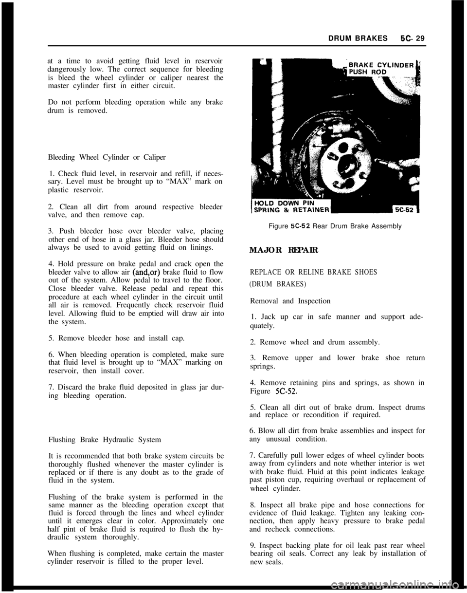
5C-52 Rear Drum Brake Assembly
MAJOR REPAIR
REPLACE OR RELINE BRAKE SHOES
(DRUM BRAKES)Removal and Inspection
1. Jack up car in safe manner and support ade-
quately.
2. Remove wheel and drum assembly.
3. Remove upper and lower brake shoe return
springs.
4. Remove retaining pins and springs, as shown in
Figure
5C-52.5. Clean all dirt out of brake drum. Inspect drums
and replace or recondition if required.
6. Blow all dirt from brake assemblies and inspect for
any unusual condition.
7. Carefully pull lower edges of wheel cylinder boots
away from cylinders and note whether interior is wet
with brake fluid. Fluid at this point indicates leakage
past piston cup, requiring overhaul or replacement of
wheel cylinder.
8. Inspect all brake pipe and hose connections for
evidence of fluid leakage. Tighten any leaking con-
nection, then apply heavy pressure to brake pedal
and recheck connections.
9. Inspect backing plate for oil leak past rear wheel
bearing oil seals. Correct any leak by installation of
new seals.
Page 289 of 625
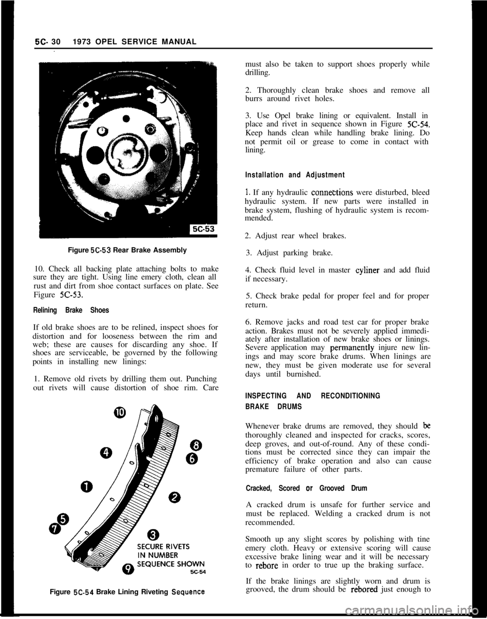
Figure 5C-53 Rear Brake Assembly
10. Check all backing plate attaching bolts to make
sure they are tight. Using line emery cloth, clean all
rust and dirt from shoe contact surfaces on plate. See
Figure Z-53.
Relining Brake ShoesIf old brake shoes are to be relined, inspect shoes for
distortion and for looseness between the rim and
web; these are causes for discarding any shoe. If
shoes are serviceable, be governed by the following
points in installing new linings:
1. Remove old rivets by drilling them out. Punching
out rivets will cause distortion of shoe rim. Care5C- 301973 OPEL SERVICE MANUAL
must also be taken to support shoes properly while
drilling.
2. Thoroughly clean brake shoes and remove all
burrs around rivet holes.
3. Use Opel brake lining or equivalent. Install in
place and rivet in sequence shown in Figure
Z-54.Keep hands clean while handling brake lining. Do
not permit oil or grease to come in contact with
lining.
Installation and Adjustment
1. If any hydraulic conne&tions were disturbed, bleed
hydraulic system. If new parts were installed in
brake system, flushing of hydraulic system is recom-
mended.
2. Adjust rear wheel brakes.
3. Adjust parking brake.
4. Check fluid level in master cyliner and add fluid
if necessary.
5. Check brake pedal for proper feel and for proper
return.
6. Remove jacks and road test car for proper brake
action. Brakes must not be severely applied immedi-
ately after installation of new brake shoes or linings.
Severe application may perinanently injure new lin-
ings and may score brake drums. When linings are
new, they must be given moderate use for several
days until burnished.
INSPECTING AND RECONDITIONING
BRAKE DRUMSWhenever brake drums are removed, they should
bethoroughly cleaned and inspected for cracks, scores,
deep groves, and out-of-round. Any of these condi-
tions must be corrected since they can impair the
efficiency of brake operation and also can cause
premature failure of other parts.
Cracked, Scored or Grooved DrumA cracked drum is unsafe for further service and
must be replaced. Welding a cracked drum is not
recommended.
Smooth up any slight scores by polishing with tine
emery cloth. Heavy or extensive scoring will cause
excessive brake lining wear and it will be necessary
to rebore in order to true up the braking surface.
Figure 5C.54 Brake Lining Riveting
SequenceIf the brake linings are slightly worn and drum is
grooved, the drum should be rebored just enough to
Page 290 of 625
DRUM BRAKES5c- 31
remove grooves, and the ridges in the lining should
be lightly removed with a lining grinder.
If brake linings are more than half worn, but do not
need replacement, the drum should be polished with
fine emery cloth but should not be rebored. At this
stage, eliminating the grooves in drum and smooth-
ing the ridges on lining would necessitate removal of
too much metal and lining, while if left alone, the
grooves and ridges match and satisfactory service
can be obtained.
If brake linings are to be replaced, a grooved drum
should be rebored for use with oversize linings. A
grooved drum, if used with new lining, will not only
wear the lining but will make it
diff%xlt, if not im-
possible, to obtain etXcient brake performance.
Out-of-Round DrumAn out-of-round drum makes accurate brake shoe
adjustment impossible and is likely to cause excessive
wear of other parts of brake mechanism due to its
eccentric action. An out-of-round drum can also
cause brake pulsation. Maximum permissible drumrunout is 004”. A drum that has more run-out than
this should be rebored. Runout can be accurately
checked by using an inside micrometer fitted with
proper extension rods.
When measuring a drum for run-out, take measure-
ments at open and closed edges of machined surface
and at right angles to each other.
Turning Brake DrumsIf a brake drum is to be turned, enough metal should
be removed to obtain a true, smooth braking surface.
Measure brake drum diameter; standard drum inner
diameter is 9.060”. Drums may be turned to an over-
size of ,030”. If maximum inner diameter after turn-
ing exceeds 9.090”, brake drum will have to be
replaced. Removal of more metal will affect dissipa-
tion of heat and may cause distortion of the drum.
1. Remove rear wheels and drums.
2. Mount brake drum on brake drum lathe and turn
drums as necessary, within limits.
3. After turning, check drum diameter. Inner diame-
ter not to exceed 9.090.
4. A newly-bored drum should always have center
contact with brake shoes. For this reason, arc grind
linings to
.OlO” under drum radius, or to ,020” under
drum diameter.
5. Clean and install drums and wheels.
BRAKE WHEEL CYLINDER OVERHAUL1. Remove wheel, drum, and brake shoes. Be careful
not to get grease or dirt on brake lining.
2. Disconnect brake pipe or hose from wheel cylinder
and cover opening with tape to prevent entrance of
dirt. Remove wheel cylinder from backing plate.
3. Remove boots, pistons, cups, and spring from cyl-
inder. Remove bleeder valve.
4. Discard rubber boots and piston cups. Thoroughly
clean all other parts with hydraulic brake fluid orDeclene. Do not use anti-freeze, alcohol, gasoline,
kerosene, or any other cleaning fluid that might con-
tain even a trace of mineral oil.
5. Inspect pistons and cylinder bore for scores, scrat-
ches, or corrosion. Light scratches may be polished
with crocus cloth. Do not use emery cloth or sandpa-
per.
Shght corro~on may be cleaned wth tine steel
wool. If scratches or corroded spots are too deep to
be polished satisfactorily, the cylinder should be re-
placed since honing is not recommended.
6. Dip internal parts in brake fluid and reassembly
wheel cylinder. When installing piston cups, use care
to avoid damaging the edges.
7. If the rear wheel backing plate is removed: Always
install new paper gaskets one on each side
- on the
backing plate. Prior to installation, lightly coat paper
gaskets with chassis lubricant. Torque backing plate
to rear axle housing bolts to 43
lb.ft. and wheel brake
cylinder to backing plate bolts to 5
lb.ft. Install wheel
cylinder on brake backing plate and connect brake
pipe or hose.
8. Install brake shoes, drum, and wheel, then flush
and bleed hydraulic system.
9. Adjust brakes, then road test car for brake per-
formance.
CAUTION:This brake backing plate to rear axle fis-
tener is an important attaching part in that it could
affect the performance of vital components and sys-
tems, and/or could result in major repair expense. It
must be replaced with one of the same part number
or with an equivalent part, if replacement becomes
necessary. Do not
use a replacement part of lesser
quahty or substitute design. Torque v&es must be
used as specified during reassembly to assure proper
retention of this part.
REPLACING BRAKE PIPESAny brake pipe assembly which is needed must be
made up from service bulk tubing and fittings. All
brake pipes must be made of tin or copper coated
wrapped steel tubing with the ends double lap flared.