OPEL GT-R 1973 Service Manual
Manufacturer: OPEL, Model Year: 1973, Model line: GT-R, Model: OPEL GT-R 1973Pages: 625, PDF Size: 17.22 MB
Page 291 of 625
5C- 321973 OPEL SERVICE MANUAL
Never use copper tubing because copper is subject to
fatigue cracking which would result in brake failure.2. Cut tubing to length. The correct length may be
determined by measuring the old pipe using a cord
and adding l/8” for each double lap flare.
To make up a brake pipe assembly, proceed as fol-
lows:3. Double lap flare tubing ends, using a suitable flar-
ing tool such as J-8051. Follow the instructions in-
cluded in the tool set. Make sure fittings are installed
1. Procure the recommended tubing and fittings of
the correct size. (Outside diameter of tubing is used
to specify size.)before starting second flare.
4. Bend pipe assembly to match old pipe.
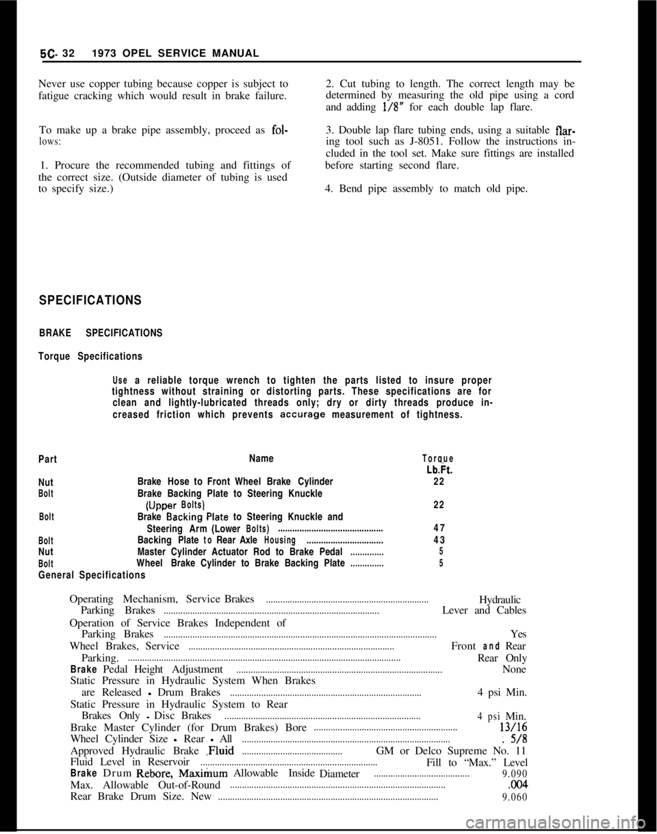
SPECIFICATIONS
BRAKE SPECIFICATIONS
Torque Specifications
Use a reliable torque wrench to tighten the parts listed to insure proper
tightness without straining or distorting parts. These specifications are for
clean and lightly-lubricated threads only; dry or dirty threads produce in-
creased friction which prevents
accurage measurement of tightness.
PartName
TorqueNut
BoltBrakeHose to Front WheelBrake Cylinder
Brake Backing Plate to Steering Knuckle(Uccer
Bolts)Lb&.
22
22...BoltBrake Backing’Plate to Steering Knuckle and
SteeringArm(Lower
Bolts)............................................
BoltBackingPlatetoRearAxleHousing................................
NutMaster Cylinder Actuator Rod to BrakePedal
..............
BoltWheelBrake Cylinder to Brake Backing Plate
..............
General Specifications47
43
5
5OperatingMechanism,ServiceBrakes
....................................................................Hydraulic
Parking Brakes
..........................................................................................Lever and Cables
Operation of Service Brakes Independent of
ParkingBrakes
..................................................................................................................Yes
WheelBrakes,Service
......................................................................................FrontandRear
Parking.
..................................................................................................................Rear Only
BrakePedalHeightAdjustment......................................................................................None
Static Pressure in Hydraulic System When Brakes
are Released
- Drum Brakes................................................................................4 psi Min.
Static Pressure in Hydraulic System to Rear
BrakesOnly
-DiscBrakes..................................................................................
4psiMin.
Brake Master Cylinder (for Drum Brakes) Bore
............................................................13/16
Wheel Cylinder Size
- Rear - All.......................................................................................: 5/8
Approved Hydraulic Brake ,Fluid
..........................................GM or Delco Supreme No. 11
Fluid Level in Reservoir
..........................................................................Fill to “Max.” Level
BrakeDrumRebore,Max&urnAllowable Inside
Diameter........................................
9.090Max. Allowable Out-of-Round
...........................................................................................CKl4Rear Brake Drum Size. New
............................................................................................
9.060
Page 292 of 625
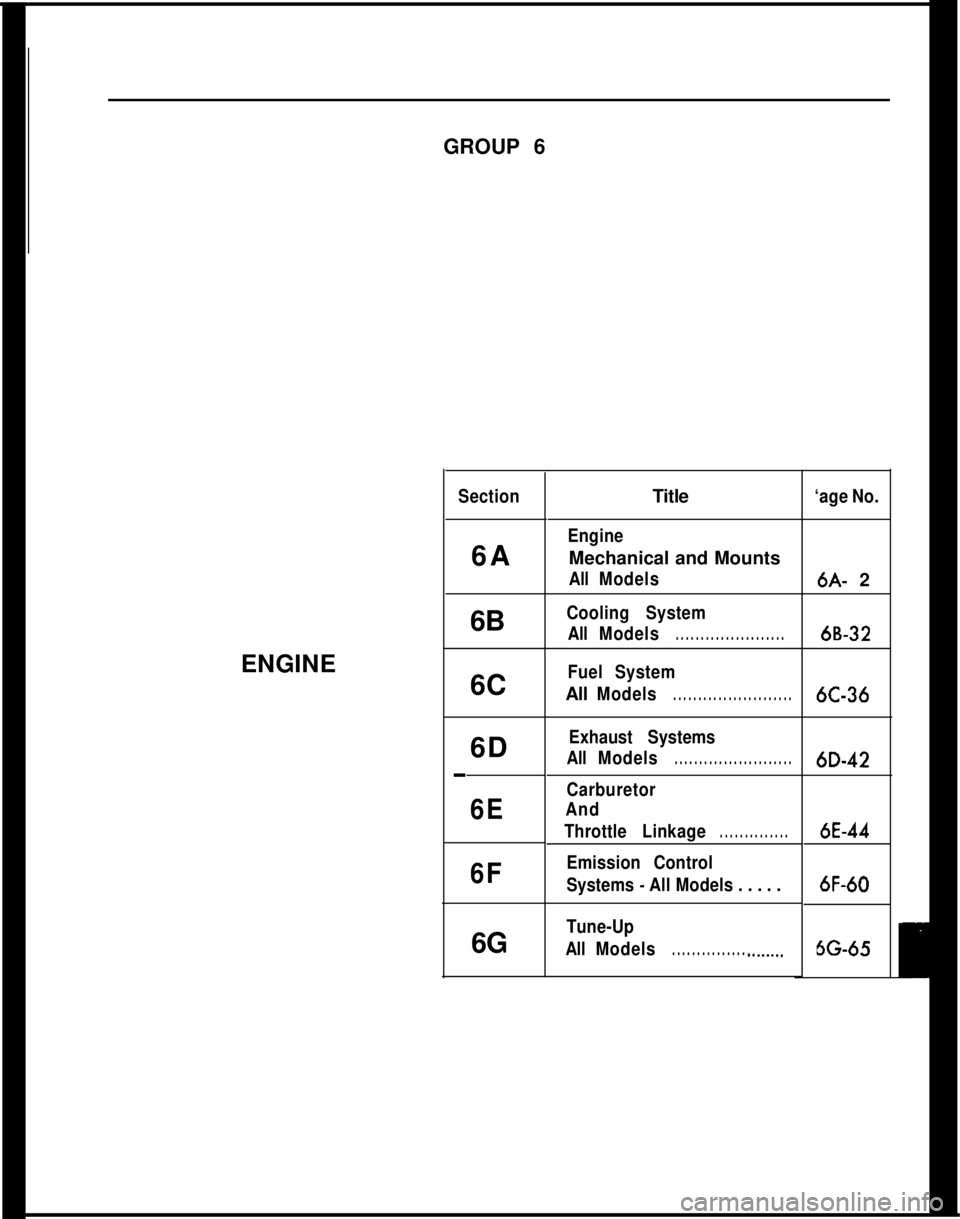
GROUP 6
ENGINESection6A
6B
6C
6D
-
6E
6F6GTitle
‘age No.
EngineMechanical and Mounts
AllModels
Cooling System
AllModels
. . . . . . . . . . . . . . . . . . . . . .
Fuel SystemAll
Models. . . . . . . . . . . . . . . . . . . . . . . .
Exhaust Systems
AllModels
. . . . . . . . . . . . . . . . . . . . . . . .
Carburetor
And
ThrottleLinkage
. . . . . . . . . . . . . .
Emission Control
Systems
- All Models . . . . .6A- 2
6B-326C-366D-42
6E-446F-60
Tune-Up
AllModels
. . . . . . . . . . . . . . . . ..__....66-65
Page 293 of 625
6A- 21973 OPEL SERVICE MANUAL
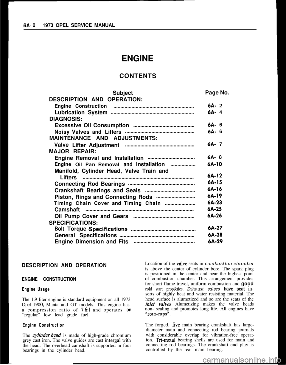
ENGINE
CONTENTS
Subject
DESCRIPTION AND OPERATION:
EngineConstruction..........................................................
LubricationSystem............................................................
DIAGNOSIS:
Excessive Oil Consumption............................................NoisyValvesandLifters..................................................
MAINTENANCE AND ADJUSTMENTS:
Valve
LifterAdjustment..................................................
MAJOR REPAIR:
Engine Removal and Installation..................................
Engine
OilPanRemoval
andInstallation..................
Manifold, Cylinder Head, Valve Train and
Lifters................................................................................
Connecting Rod Bearings................................................
Crankshaft Bearings and Seals....................................
Piston, Rings and Connecting Rods............................
TimingChainCoverandTimingChain......................
Camshaft..............................................................................
Oil Pump Cover and Gears............................................
SPECIFICATIONS:
BoltTorque.Specifications
..............................................General Specifications......................................................
Engine Dimension and Fits............................................Page No.
6A- 2
6A- 4
6A- 6
6A- 6
6A- 7
6A- 86A-106A-126A-156A-166A-196A-236A-256A-266A-276A-286A-29
DESCRIPTION AND OPERATION
ENGINE CONSTRUCTION
Engine UsageThe 1.9 liter engine is standard equipment on all 1973
Opel
1900, Manta and GT models. This engine has
a compression ratio of
7.6:1 and operates on“regular” low lead grade fuel.
Engine ConstructionThe
cyfinderhead is made of high-grade chromium
grey cast iron. The valve guides are cast intergal with
the head. The overhead camshaft is supported in four
bearings in the cylinder head.Location of the
vzllve seats in combustion chamber
is above the center of cylinder bore. The spark plug
is positioned in the center and near the highest point
of combustion chamber. This arrangement provides
for short flame travel, uniform combustion and good
cold start prop&ties. Exhaust valves have seat in-serts of highly heat and water resisting material. The
head surface is alumetized and so are the seats of the
inlet v&es Alumetizing makes the valve heads
non- scaling and promotes long life. All engines have“rota-caps”.
The forged, five main bearing crankshaft has large-
diameter main and connecting rod bearing journals
with considerable overlap for vibration-free operat-
ion. T&metal bearing shells are used for main and
connecting rod bearings. The crankshaft end play is
controlled by the rear main bearing.
Page 294 of 625
ENGINE MECHANICAL AND MOUNTS6A- 3
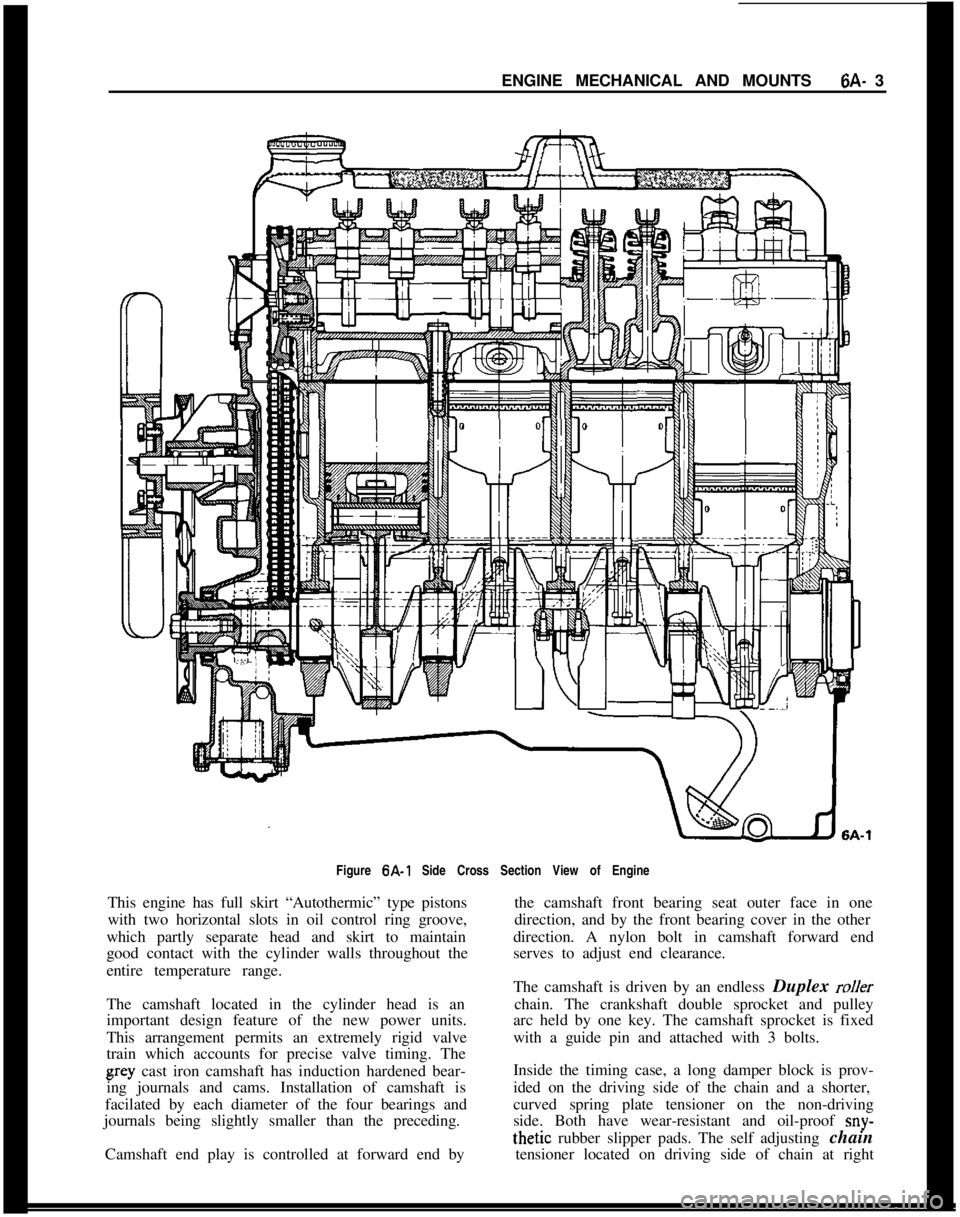
Figure 6A-1 Side Cross Section View of Engine
This engine has full skirt “Autothermic” type pistons
with two horizontal slots in oil control ring groove,
which partly separate head and skirt to maintain
good contact with the cylinder walls throughout the
entire temperature range.
The camshaft located in the cylinder head is an
important design feature of the new power units.
This arrangement permits an extremely rigid valve
train which accounts for precise valve timing. Thegray cast iron camshaft has induction hardened bear-
ing journals and cams. Installation of camshaft is
facilated by each diameter of the four bearings and
journals being slightly smaller than the preceding.
Camshaft end play is controlled at forward end bythe camshaft front bearing seat outer face in one
direction, and by the front bearing cover in the other
direction. A nylon bolt in camshaft forward end
serves to adjust end clearance.
The camshaft is driven by an endless Duplex
rollerchain. The crankshaft double sprocket and pulley
arc held by one key. The camshaft sprocket is fixed
with a guide pin and attached with 3 bolts.
Inside the timing case, a long damper block is prov-
ided on the driving side of the chain and a shorter,
curved spring plate tensioner on the non-driving
side. Both have wear-resistant and oil-proof
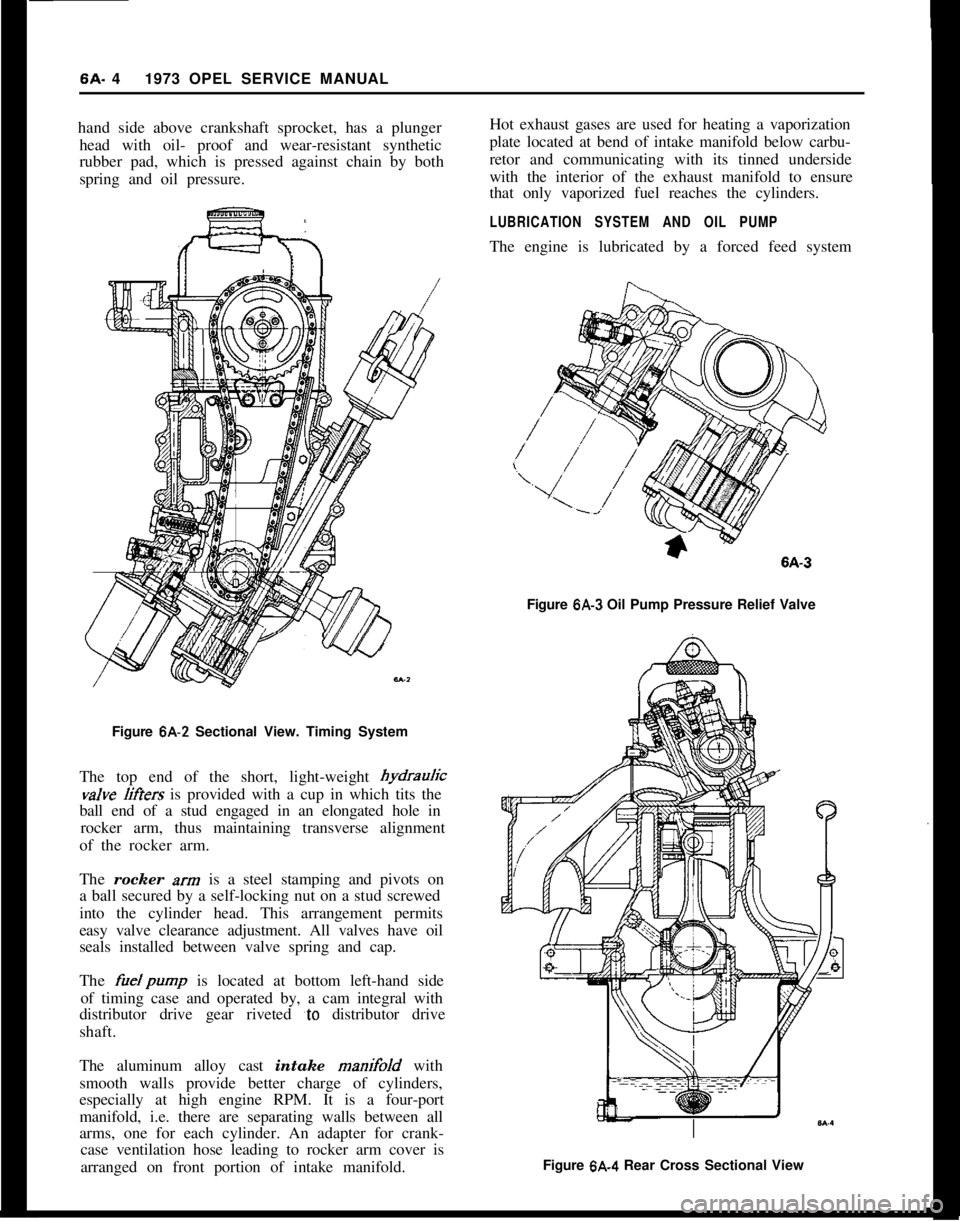
sny-thetic rubber slipper pads. The self adjusting chain
tensioner located on driving side of chain at right
Page 295 of 625
6A. 41973 OPEL SERVICE MANUAL
hand side above crankshaft sprocket, has a plunger
head with oil- proof and wear-resistant synthetic
rubber pad, which is pressed against chain by both
spring and oil pressure.
Figure 6A-2 Sectional View. Timing System
The top end of the short, light-weight hydrauricvalve
liffers is provided with a cup in which tits the
ball end of a stud engaged in an elongated hole in
rocker arm, thus maintaining transverse alignment
of the rocker arm.
The rocker
xrn is a steel stamping and pivots on
a ball secured by a self-locking nut on a stud screwed
into the cylinder head. This arrangement permits
easy valve clearance adjustment. All valves have oil
seals installed between valve spring and cap.
The
fuelpump is located at bottom left-hand side
of timing case and operated by, a cam integral with
distributor drive gear riveted
‘to distributor drive
shaft.
The aluminum alloy cast intake manifold with
smooth walls provide better charge of cylinders,
especially at high engine RPM. It is a four-port
manifold, i.e. there are separating walls between all
arms, one for each cylinder. An adapter for crank-
case ventilation hose leading to rocker arm cover is
arranged on front portion of intake manifold.Hot exhaust gases are used for heating a vaporization
plate located at bend of intake manifold below carbu-
retor and communicating with its tinned underside
with the interior of the exhaust manifold to ensure
that only vaporized fuel reaches the cylinders.
LUBRICATION SYSTEM AND OIL PUMPThe engine is lubricated by a forced feed system
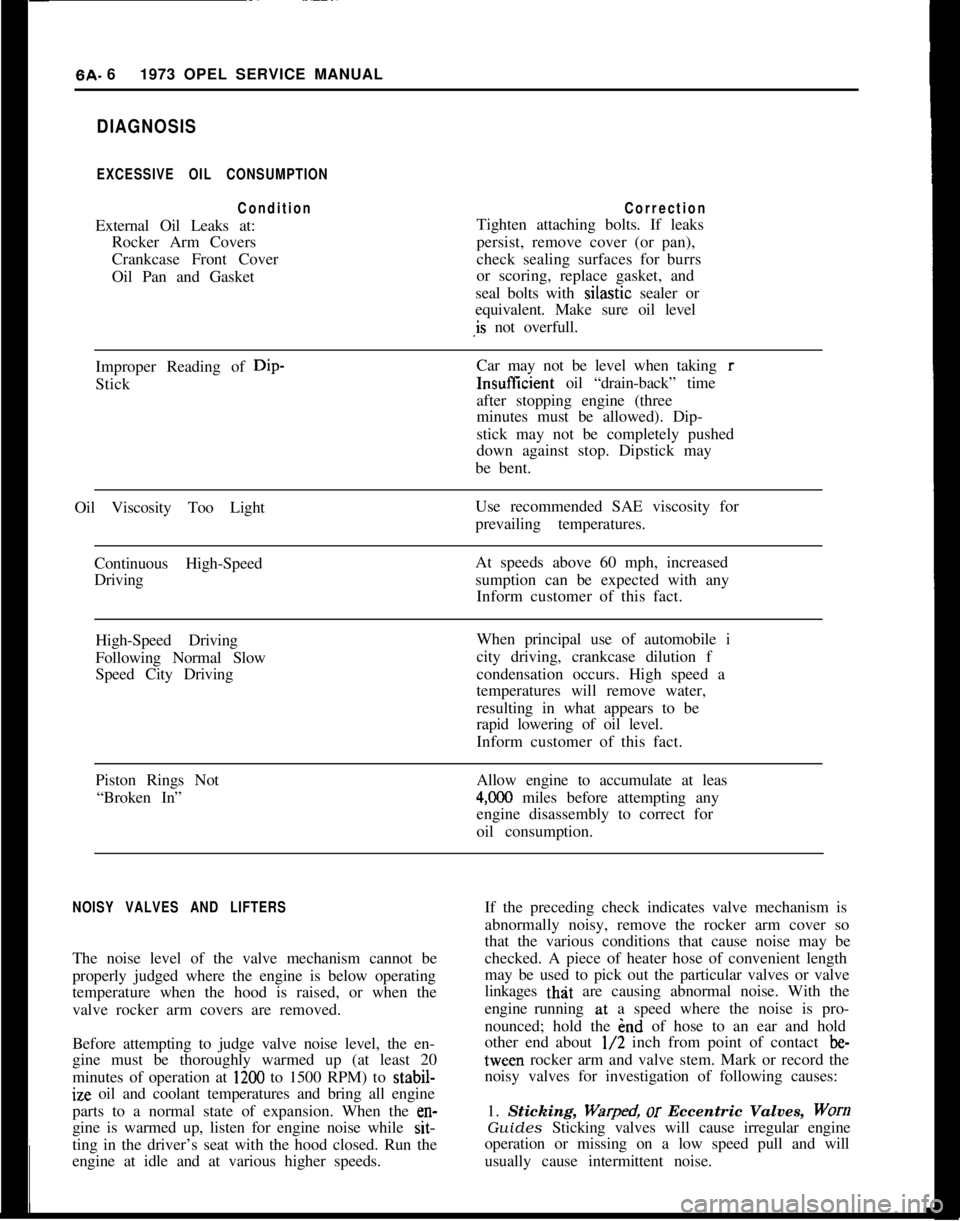
Figure
6A-3 Oil Pump Pressure Relief Valve
Figure 6A.4 Rear Cross Sectional View
Page 296 of 625
ENGINE MECHANICAL AND MOUNTS6A- 5
incorporating a gear-type pump driven by the dis-
tributor shaft. The pump body forms part of the
timing case. A passage cast in cylinder block and a
suction pipe connect the pump to the screen cover
assembly in the sump of the oil pan.
The oil pump pressure relief valve is located in the
engine oil pump cover. See Figure 6A-3. The pres-
sure relief valve serves to feed surplus oil back into
the suction passage should the required oil pressure
be exceeded. The old oil pressure relief valve which
is located above the oil filter is inoperative. A heavier
spring has been installed to keep the valve seated at
all times.
The oil filter is of the full flow type. With it in paral-
lel is a by-pass system controlled by a valve in the
timing chain cover above the oil filter which ensures
oil circulation directly to lubrication points if ele-
ment becomes clogged by dirt or oil is too thick to
pass through. Only when oil flow through element is
unrestricted the by-pass valve will close and filtered
oil is fed to the engine.
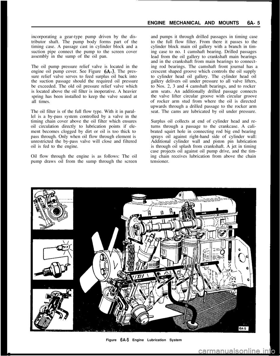
Oil flow through the engine is as follows: The oil
pump draws oil from the sump through the screenand pumps it through drilled passages in timing case
to the full flow filter. From there it passes to the
cylinder block main oil gallery with a branch in tim-
ing case to no. 1 camshaft bearing. Drilled passages
lead from the oil gallery to crankshaft main bearings
and in the crankshaft from main bearings to connect-
ing rod bearings. The camshaft front journal has a
crescent shaped groove which controls the oil supply
to cylinder head oil gallery. The cylinder head oil
gallery delivers oil under pressure to all valve lifters,
to Nos. 2, 3 and 4 camshaft bearings, and to rocker
arm seats. An additionally drilled passage connects
the valve lifter circular groove with circular groove
of rocker arm stud from where the oil is directed
upwards through a drilled passage to the rocker arm
seat. The cams are lubricated by oil under pressure.
Surplus oil collects at end of cylinder head and re-
turns through a passage to the crankcase. A cali-
brated squirt hole in connecting rod big end bearing
sprays oil against right-hand side of cylinder wall:
Additional cylinder wall and piston pin lubrication
is through oil splash from crankshaft. A jet in timing
case projects oil against oil pump drive, and the tim-
ing chain receives lubrication from above the chain
tensioner.
Figure 6A-5 Engine Lubrication System
Page 297 of 625
6A. 61973 OPEL SERVICE MANUALDIAGNOSIS
EXCESSIVE OIL CONSUMPTION
ConditionCorrectionExternal Oil Leaks at:Tighten attaching bolts. If leaks
Rocker Arm Coverspersist, remove cover (or pan),
Crankcase Front Covercheck sealing surfaces for burrs
Oil Pan and Gasketor scoring, replace gasket, and
seal bolts with silastic sealer or
equivalent. Make sure oil level
,is not overfull.
Improper Reading of Dip-Car may not be level when taking r
StickInsuffIcient oil “drain-back” time
after stopping engine (three
minutes must be allowed). Dip-
stick may not be completely pushed
down against stop. Dipstick may
be bent.
Oil Viscosity Too LightUse recommended SAE viscosity for
prevailing temperatures.
Continuous High-SpeedAt speeds above 60 mph, increased
Drivingsumption can be expected with any
Inform customer of this fact.
High-Speed DrivingWhen principal use of automobile i
Following Normal Slowcity driving, crankcase dilution f
Speed City Drivingcondensation occurs. High speed a
temperatures will remove water,
resulting in what appears to be
rapid lowering of oil level.
Inform customer of this fact.
Piston Rings NotAllow engine to accumulate at leas
“Broken In”
4,OCO miles before attempting any
engine disassembly to correct for
oil consumption.
NOISY VALVES AND LIFTERSIf the preceding check indicates valve mechanism is
abnormally noisy, remove the rocker arm cover so
that the various conditions that cause noise may be
The noise level of the valve mechanism cannot bechecked. A piece of heater hose of convenient length
properly judged where the engine is below operatingmay be used to pick out the particular valves or valve
temperature when the hood is raised, or when thelinkages
thit are causing abnormal noise. With the
valve rocker arm covers are removed.engine running at a speed where the noise is pro-
nounced; hold the end of hose to an ear and hold
Before attempting to judge valve noise level, the en-other end about
l/2 inch from point of contact be-
gine must be thoroughly warmed up (at least 20tween rocker arm and valve stem. Mark or record the
minutes of operation at
1200 to 1500 RPM) to stabil-noisy valves for investigation of following causes:ize oil and coolant temperatures and bring all engine
parts to a normal state of expansion. When the
en-1. Sticking, Warped, or Eccentric Valves, Worngine is warmed up, listen for engine noise while
sit-Guides Sticking valves will cause irregular engine
ting in the driver’s seat with the hood closed. Run theoperation or missing on a low speed pull and will
engine at idle and at various higher speeds.usually cause intermittent noise.
Page 298 of 625
ENGINE MECHANICAL AND MOUNTS6A- 7
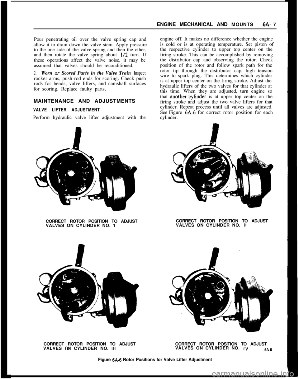
Pour penetrating oil over the valve spring cap andengine off. It makes no difference whether the engine
allow it to drain down the valve stem. Apply pressureis cold or is at operating temperature. Set piston of
to the one side of the valve spring and then the other,the respective cylinder to upper top center on the
and then rotate the valve spring about l/2 turn. Iffiring stroke. This can be accomplished by removing
these operations affect the valve noise, it may bethe distributor cap and observing the rotor. Check
assumed that valves should be reconditioned.position of the rotor and follow spark path for the
2.Worn or Scored Parts in the Valve Train Inspectrotor tip through the distributor cap, high tension
rocker arms, push rod ends for scoring. Check pushwire to spark plug. This determines which cylinder
rods for bends, valve lifters, and camshaft surfacesis at upper top center on the firing stroke. Adjust the
for scoring. Replace faulty parts.hydraulic lifters of the two valves for that cylinder at
this time. When they are adjusted, turn engine so
MAINTENANCE AND ADJUSTMENTSthat another.cylinder is at upper top center on the
firing stroke and adjust the two valve lifters for that
VALVE LIFTER ADJUSTMENTcylinder. Repeat process until all valves are adjusted.
See Figure 6A-6 for correct rotor position for each
Perform hydraulic valve lifter adjustment with thecylinder.
CORRECT ROTOR POSITION TO ADJUSTCORRECT ROTOR POSITION TO ADJUST
VALVES ON CYLINDER NO. 1VALVES ON CYLINDER NO. II
CORRECT ROTOR POSITION TO ADJUSTCORRECT ROTOR POSITION TO ADJUST
VALVES
ON CYLINDER NO. IllVALVES ON CYLINDER NO. ,VW-6Figure
6A-6 Rotor Positions for Valve Lifter Adjustment
Page 299 of 625
6A- 8 1973 OPEL SERVICE MANUAL
Actual adjustment is made by backing off adjusting
nut at the rocker arm until clearance exists between the valve stem, rocker arm, and lifter. Then slowly
tighten adjusting nut until clearance is eliminated.
When clearance is eliminated, turn adjusting nut one
full turn (clockwise). This positions the hydraulic
piston of the hydraulic lifter mid-point in its total
available travel, and no further adjustment is re-
quired.
MAJOR REPAIR
ENGINE ASSEMBLY REMOVAL AND
INSTALLATION
Removal (Opel 1900 and Manta)’
The engine assembly on the Opel 1900 and Manta
can be removed together with the transmission
through the top of the engine compartment.
1. Remove hood (scribe hood hinge to hood mount-
ing location).
2. Disconnect battery negative cable.
3. Drain coolant at lower radiator hose.
4. Remove upper and lower radiator hoses.
5. Remove radiator and fan
shrbud.
6. Disconnect heater hoses.
7. Disconnect brake booster
vacuum hose.
8. Remove air cleaner.
9. Disconnect electrical connections and accelerator
linkage. 10. Remove console.
11. Remove shift lever boot, plate, and shift lever.
12. Raise car on hoist.
13. Disconnect fuel line at pump.
14. Remove front stone shield.
15. Disconnect speedo-cable, back-up light switch,
and clutch cable.
16. Remove drive shaft. I
17. Disconnect exhaust pipe
ar$l bell housing sup-
port.
18. Disconnect transmission support. See Figure
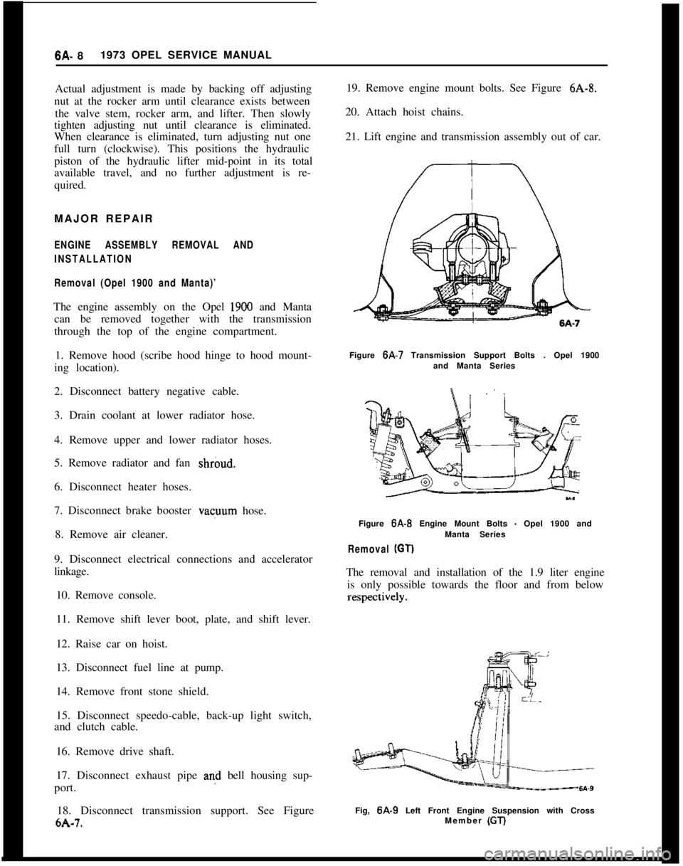
6A-7. 19. Remove engine mount bolts. See Figure
6A-8.
20. Attach hoist chains.
21. Lift engine and transmission assembly out of car.
Figure 6A-7 Transmission Support Bolts . Opel 1900
and Manta Series
Figure
6A-B Engine Mount Bolts - Opel 1900 and
Manta Series
Removal (GT)
The removal and installation of the 1.9 liter engine is only possible towards the floor and from below
Fig, 6A-9 Left Front Engine Suspension with Cross
Member (GT)
Page 300 of 625
ENGINE MECHANICAL AND MOUNTS6A- 9
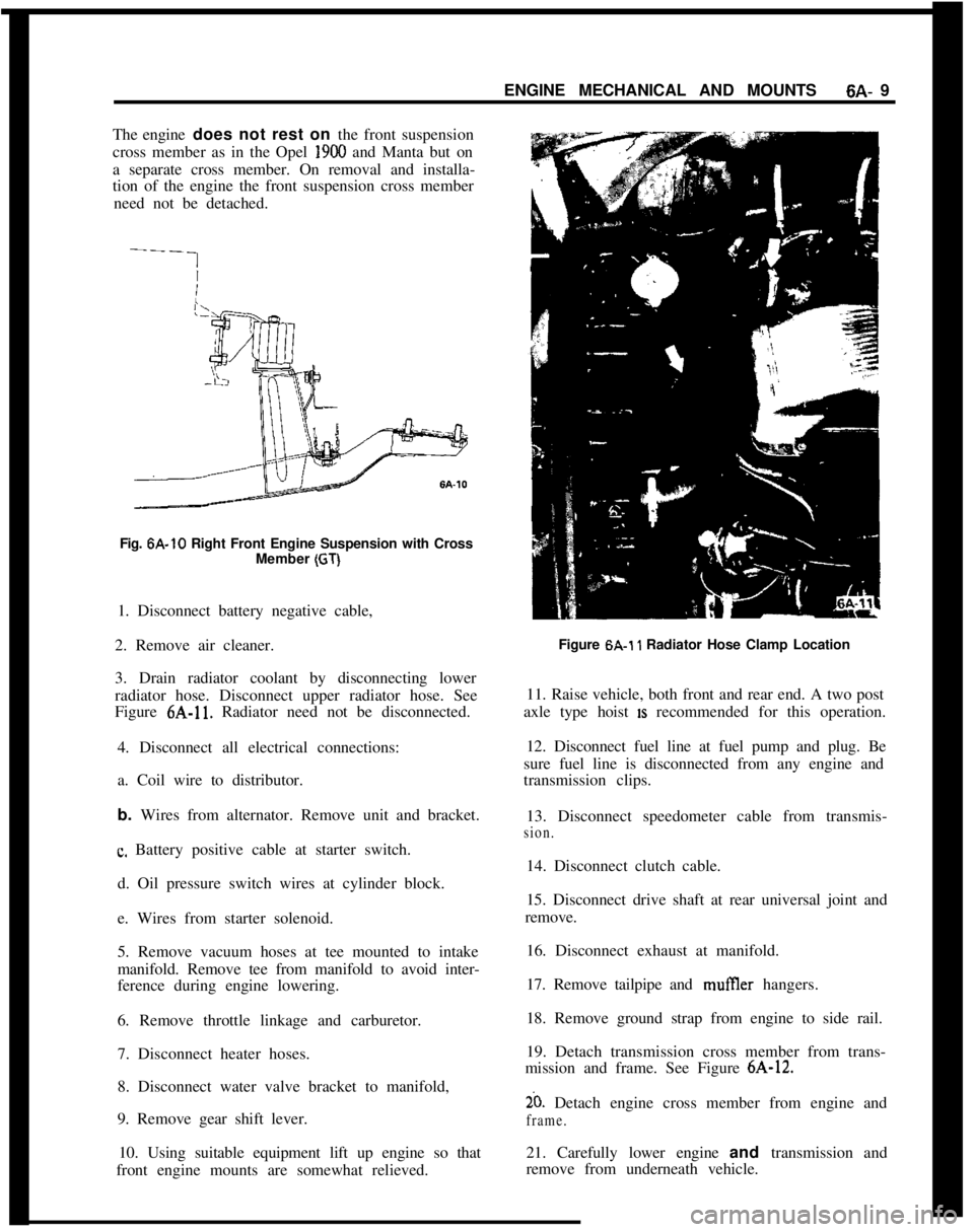
The engine does not rest on the front suspension
cross member as in the Opel 1900 and Manta but on
a separate cross member. On removal and installa-
tion of the engine the front suspension cross member
need not be detached.
Fig. 6A-10 Right Front Engine Suspension with Cross
Member
(GT)1. Disconnect battery negative cable,
2. Remove air cleaner.
3. Drain radiator coolant by disconnecting lower
radiator hose. Disconnect upper radiator hose. See
Figure 6A-11. Radiator need not be disconnected.
4. Disconnect all electrical connections:
a. Coil wire to distributor.
b. Wires from alternator. Remove unit and bracket.
c. Battery positive cable at starter switch.
d. Oil pressure switch wires at cylinder block.
e. Wires from starter solenoid.
5. Remove vacuum hoses at tee mounted to intake
manifold. Remove tee from manifold to avoid inter-
ference during engine lowering.
6. Remove throttle linkage and carburetor.
7. Disconnect heater hoses.
8. Disconnect water valve bracket to manifold,
9. Remove gear shift lever.
10. Using suitable equipment lift up engine so that
front engine mounts are somewhat relieved.Figure 6A.1
1 Radiator Hose Clamp Location
11. Raise vehicle, both front and rear end. A two post
axle type hoist
IS recommended for this operation.
12. Disconnect fuel line at fuel pump and plug. Be
sure fuel line is disconnected from any engine and
transmission clips.
13. Disconnect speedometer cable from transmis-
sion.14. Disconnect clutch cable.
15. Disconnect drive shaft at rear universal joint and
remove.
16. Disconnect exhaust at manifold.
17. Remove tailpipe and mufIler hangers.
18. Remove ground strap from engine to side rail.
19. Detach transmission cross member from trans-
mission and frame. See Figure 6A-12.
20. Detach engine cross member from engine and
frame.21. Carefully lower engine and transmission and
remove from underneath vehicle.