PONTIAC FIERO 1988 Service Repair Manual
Manufacturer: PONTIAC, Model Year: 1988, Model line: FIERO, Model: PONTIAC FIERO 1988Pages: 1825, PDF Size: 99.44 MB
Page 1301 of 1825
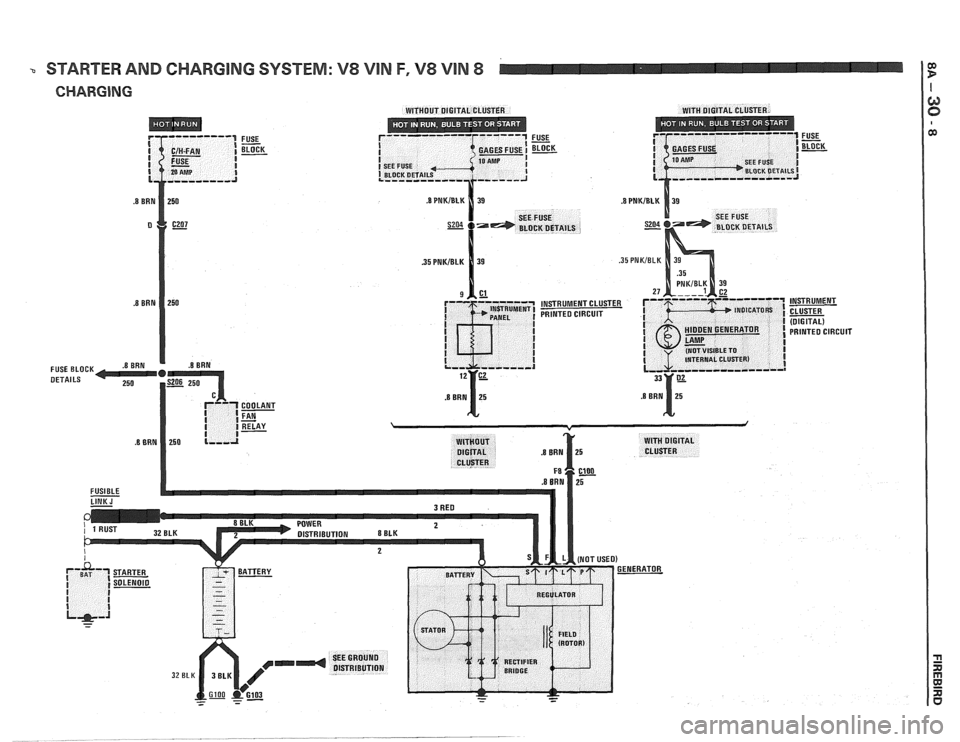
a STARTER AND CHARGING SYSTEM: V8 VIN F, V8 VlN 8 C
Page 1302 of 1825
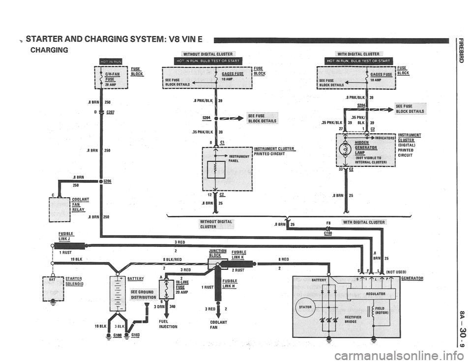
STARTER AND CHARGING SYSTEM: V8 VIN E
CHARGING WITHOUT DIGITAL CLUSTER WITH DIGITAL CLUSTER
------ I= I FUSE C/H-FAN I BLOCK I GAGES FUSE =K FUSE - SEE FUSE I
( BLOCK DETAILS I
--,,--a
Page 1303 of 1825
STARTER AND CHARGING SYSTEM
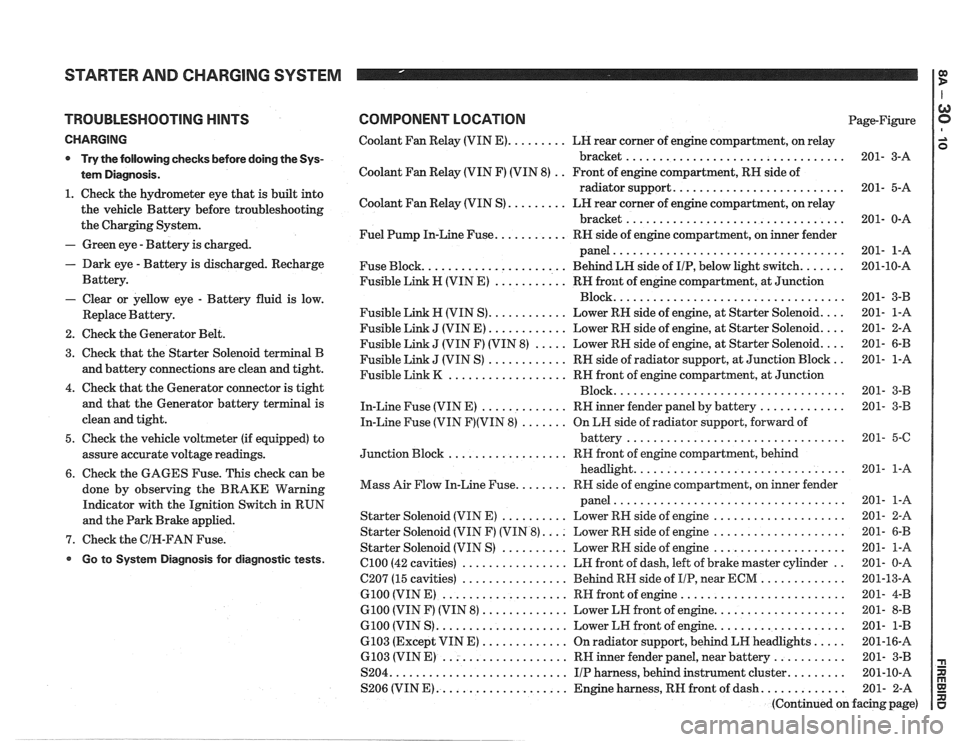
TROUBLESHOOTING HINTS
CHARGING
* Try the following checks before doing the Sys-
tem Diagnosis
.
1 . Check the hydrometer eye that is built into
the vehicle Battery before troubleshooting
the Charging System
.
- Green eye . Battery is charged .
. Dark eye . Battery is discharged . Recharge
Battery
.
- Clear or yellow eye . Battery fluid is low .
Replace Battery .
2 . Check the Generator Belt .
3 . Check that the Starter Solenoid terminal B
and battery connections are clean and tight
.
4 . Check that the Generator connector is tight
and that the Generator battery terminal is
clean and tight
.
5 . Check the vehicle voltmeter (if equipped) to
assure accurate voltage readings
.
6 . Check the GAGES Fuse . This check can be
done by observing the BRAKE Warning
Indicator with the Ignition Switch in RUN
and the Park Brake applied
.
7 . Check the GIN-FAN Fuse .
Go to System Diagnosis for diagnostic tests .
COMPONENT LOCATION Page-Figure
Coolant Fan Relay (VIN
E) ......... LH rear corner of engine compartment. on relay
bracket
................................. 201- 3-A
Coolant Fan Relay (VIN F) (VIN 8)
. . Front of engine compartment. RH side of
radiator support
.......................... 201- 5-A
Coolant Fan Relay (VIN S)
......... LN rear corner of engine compartment. on relay
bracket
................................. 201- 0-A
Fuel Pump In-Line Fuse
........... RH side of engine compartment. on inner fender
panel
................................... 201- 1-A
Fuse Block
...................... Behind LN side of IIP. below light switch ....... 201-10-A
Fusible Link H (VIN E)
........... RH front of engine compartment. at Junction
................................... Block 201- 3-B
Fusible Link
H (VIN S) ............ Lower RN side of engine. at Starter Solenoid .... 201- 1-A
Fusible Link
J (VIN E) ............ Lower RH side of engine. at Starter Solenoid .... 201- 2-A
Fusible Link
J (VIN F) (VIN 8) ..... Lower RH side of engine. at Starter Solenoid .... 201- 6-B
Fusible Link
J (VIN S) ............ RH side of radiator support. at Junction Block .. 201- 1-A
Fusible Link
K .................. RH front of engine compartment. at Junction
................................... Block 201- 3-B
In-Line Fuse (VIN E)
............. RH inner fender panel by battery ............. 201- 3-B
In-Line Fuse (VIN
F)(VIN 8) ....... On LH side of radiator support. forward of
................................. battery 201- 5-6
.................. Junction Block RH
front of engine compartment. behind
................................ headlight 201- 1-A
........ Mass Air Flow In-Line Fuse RR side of engine compartment. on inner fender
................................... panel 201- 1-A
Starter Solenoid (VIN E)
.......... Lower RH side of engine .................... 201- 2-A
Starter Solenoid (VIN F) (VIN
8) .... Lower RH side of engine .................... 201- 6-B
Starter Solenoid (VIN S)
.......... Lower RN side of engine .................... 201- 1-A
el00 (42 cavities) ................ LH front of dash. left of brake master cylinder .. 201- 0-A
C207 (15 cavities)
................ Behind RH side of IIP. near ECM ............. 201-13-A
G100 (VIN E) ................... RH front of engine ......................... 201- 4-B
G100 (VIN F) (VIN 8) ............. Lower LH front of engine .................... 201- 8-B
G100 (VIN S) .................... Lower LH front of engine .................... 201- 1-B
6103 (Except VIN E) ............. On radiator support. behind LH headlights ..... 201-16-A
6.103 (VIN E) ................... RH inner fender panel. near battery ........... 201- 3-B
S204
........................... IIP harness. behind instrument cluster ......... 201-10-A
S206 (VIN
E) .................... Engine harness. RH front of dash ............. 201- 2-A
(Continued on facing page)
Page 1304 of 1825
STARTER AND CHARGING SYSTEM
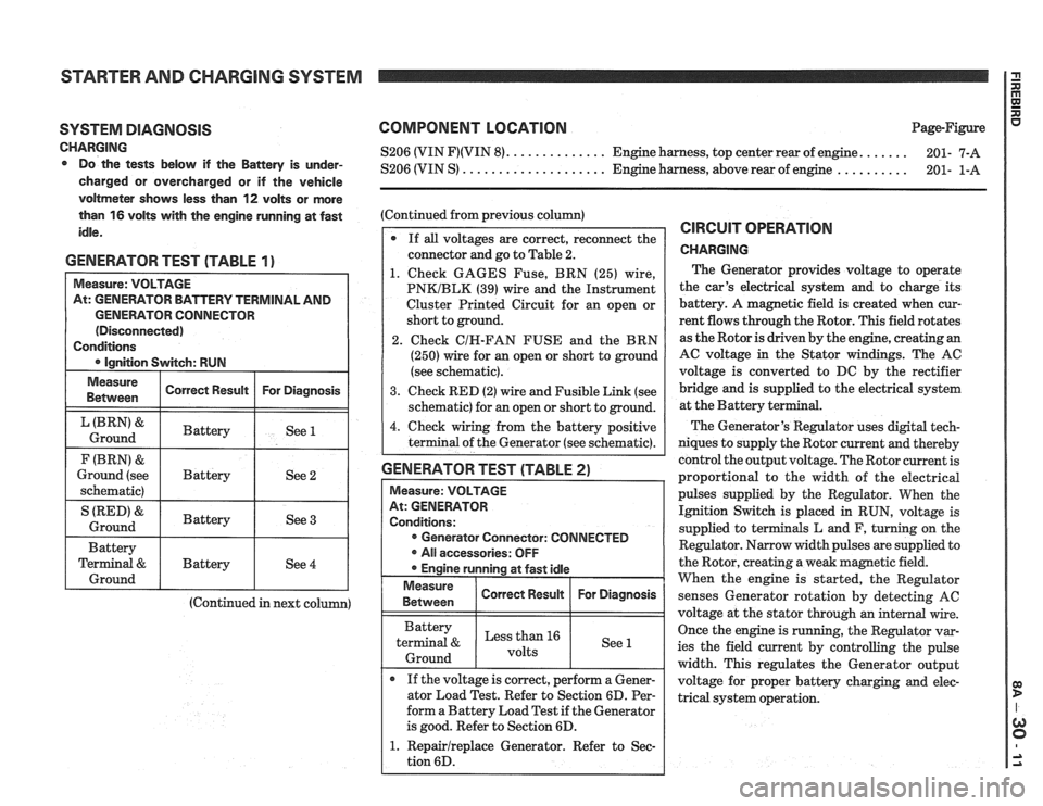
SYSTEM DIAGNOSIS
CHARGING Do the tests below if the Battery is under-
charged or overcharged or if the vehicle
voltmeter shows less than
12 volts or more
than
16 volts with the engine running at fast
idle.
GENERATOR TEST (TABLE 1)
GENERATOR CONNECTOR
(Continued in next column)
COMPONENT LOCATION Page-Figure
...... S206 (VIN F)(VIN 8). ............. Engine harness, top center rear of engine.
201- 7-A
.......... S206 (VIN S) .................... Engine harness, above rear of engine
201- 1-A
(Continued from previous column)
If
all voltages are correct, reconnect the
connector and go to Table 2.
1. Check GAGES Fuse, BRN (25) wire,
PNKIBLK (39) wire and the Instrument
Cluster Printed Circuit for an open or
short to ground.
2. Check
CIH-FAN FUSE and the BRN
(250) wire for an open or short to ground
(see schematic).
3. Check RED (2) wire and Fusible Link (see
schematic) for an open or short to ground.
4. Check wiring from the battery positive
terminal of the Generator (see schematic).
GENERATOR TEST (TABLE 2)
Measure: VOLTAGE
At: GENERATOR
Conditions: Generator Connector: CONNECTED
All accessories: OFF
Engine running at fast idle
Measure I Correct Resuk I For Diagnosis / 1 Between
Battery
terminal
& Less than 16
1 Ground 1 1 See 1
If the voltage is correct, perform a Gener-
ator Load Test. Refer to Section 6D. Per-
form a Battery Load Test if the Generator
is good. Refer to Section 6D.
1. Repairlreplace Generator. Refer to Sec-
tion 6D.
CIRCUIT OPERATION
CHARGING
The Generator provides voltage to operate
the car's electrical system and to charge its
battery. A magnetic field is created when cur-
rent flows through the Rotor. This field rotates
as the Rotor is driven by the engine, creating an
AC voltage in the Stator windings. The AC
voltage is converted to DC by the rectifier
bridge and is supplied to the electrical system
at the Battery ter
The Generator's Regulator uses digital tech-
niques to supply the Rotor current and thereby
control the output voltage. The Rotor current is
proportional to the width of the electrical
pulses supplied by the Regulator. When the
Ignition Switch is placed in RUN, voltage is
supplied to terminals L and F, turning on the
Regulator. Narrow width pulses are supplied to
the Rotor, creating a weak magnetic field.
When the engine is started, the Regulator
senses Generator rotation by detecting
AC
voltage at the stator through an internal wire.
Once the engine is running, the Regulator var-
ies the field current by controlling the pulse
width. This regulates the Generator output
voltage for proper battery charging and elec-
trical system operation.
Page 1305 of 1825
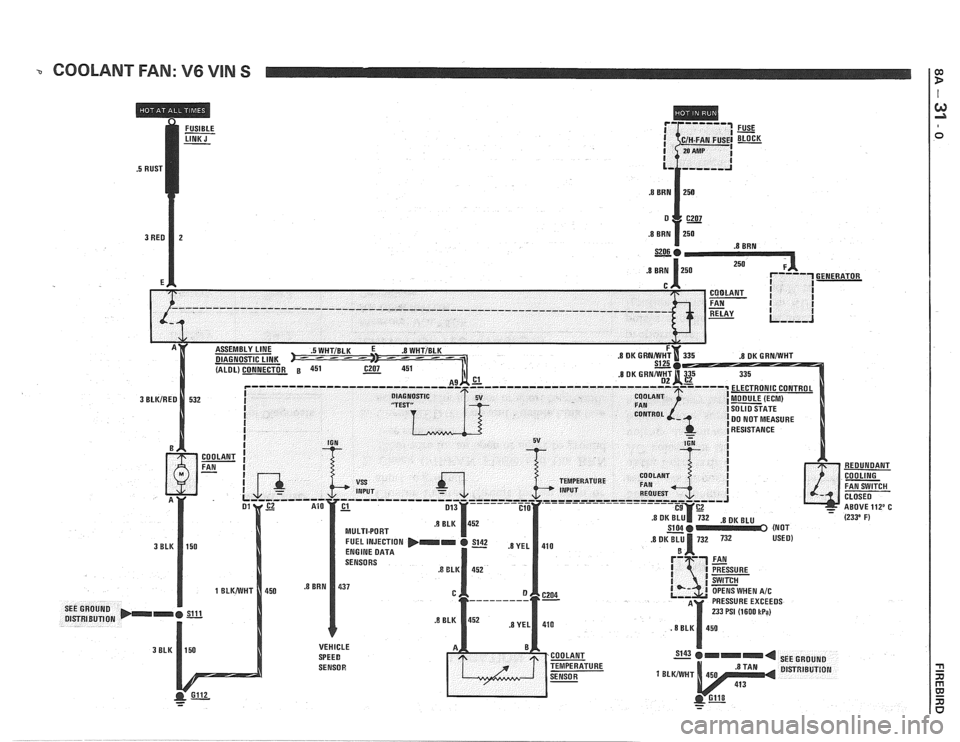
-. COOLANT FAN: V6 VIN S $
I
Page 1306 of 1825
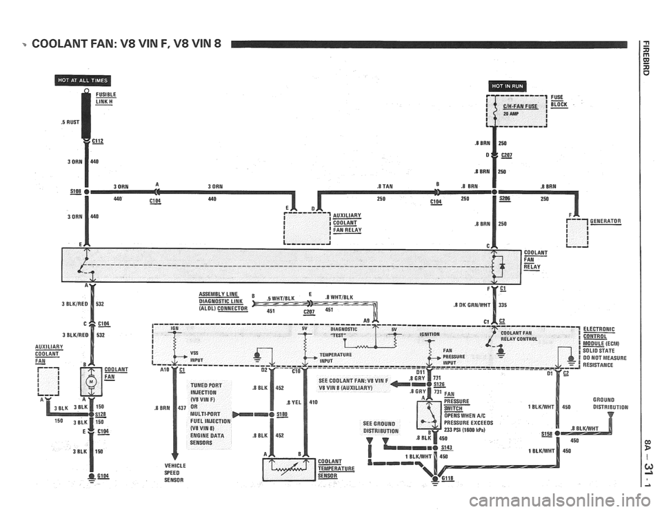
COOLANT FAN: V8 VIN F, V8 VIN 8
DIAGNOSTIC LINK (ALDL) CONNECTOR SEE COOLANT FAN:
V8 VIN F V8 VIN 8 (AUXILIARY)
SEE GROUND PRESSURE EXCEEDS
DISTRIBUTION
233 PSI (1600 ItPa)
VEHICLE
Page 1307 of 1825
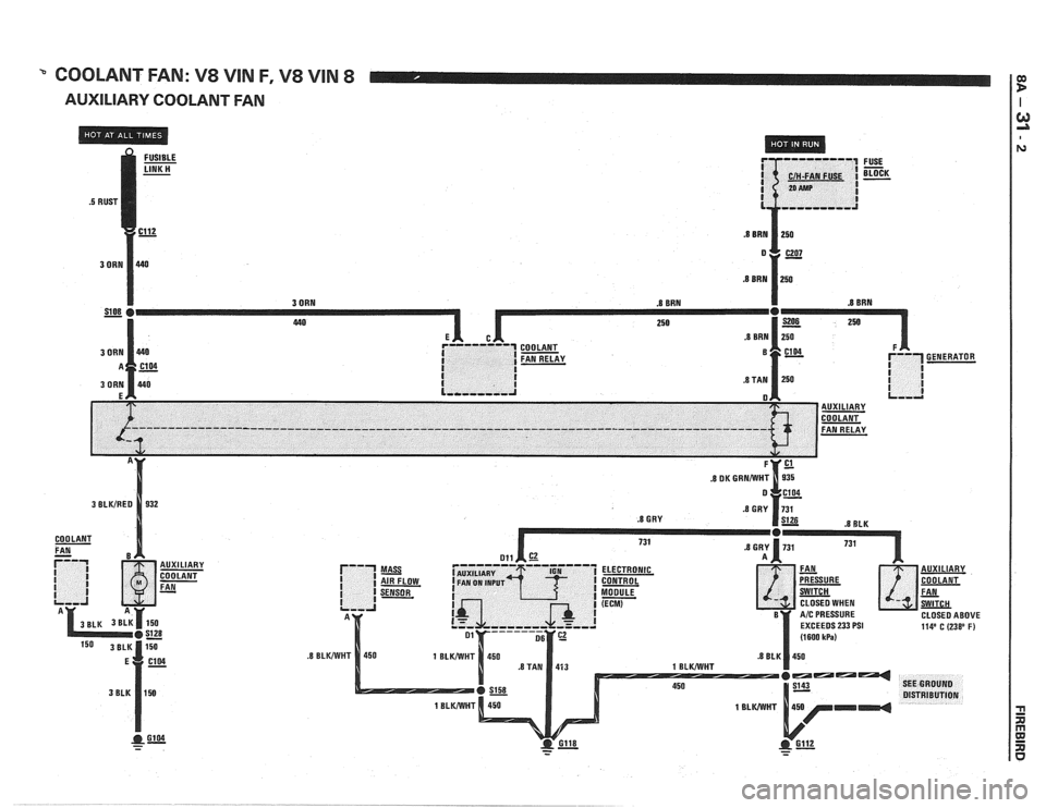
" COOLANT FAN: V8 VIN F, V8 VIN 8
AUXILIARY COOLANT FAN
.8 GRY .8 BLK
CLOSED WHEN
CLOSED ABOVE
EXCEEDS
233 PSI 114' C (238' F)
- - - -
Page 1308 of 1825
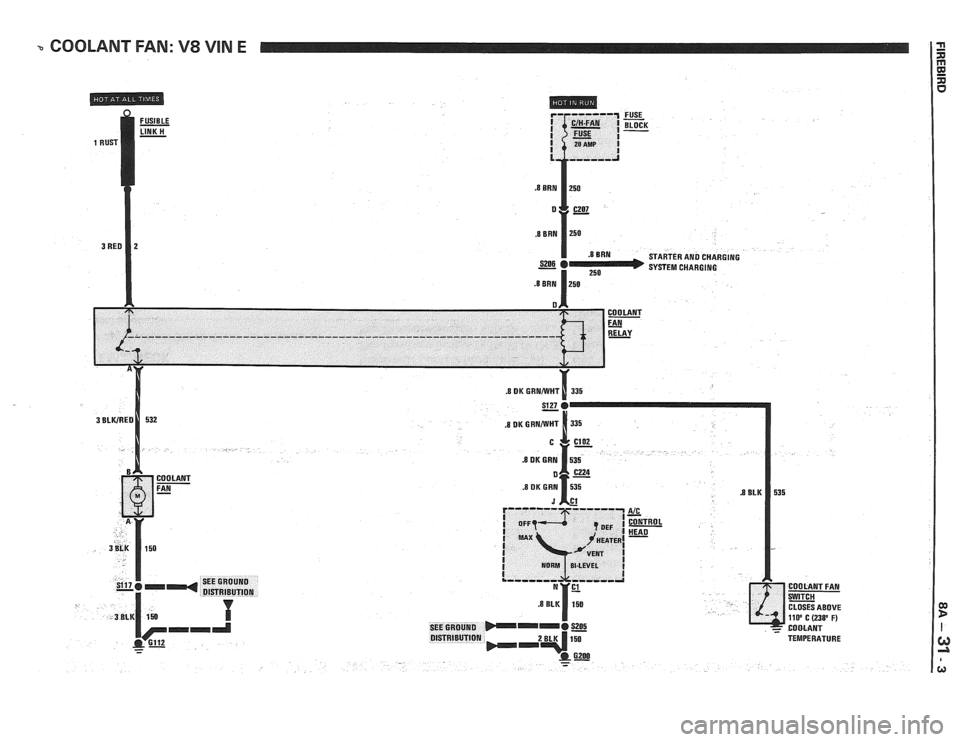
- COOLANT FAN: V8 VIN E
FUSIBLE - LINK H -
FUSE - BLOCK -
STARTER AN0 CHARGING
1 250 SYSTEM CHARGING .B BRN 1250
COOLANT
FAN SE CLOSES ABOVE llOo C (23S0 F) IEGROUND COMANT QlSTRlEUTlQN TEMPERATURE
- -
Page 1309 of 1825
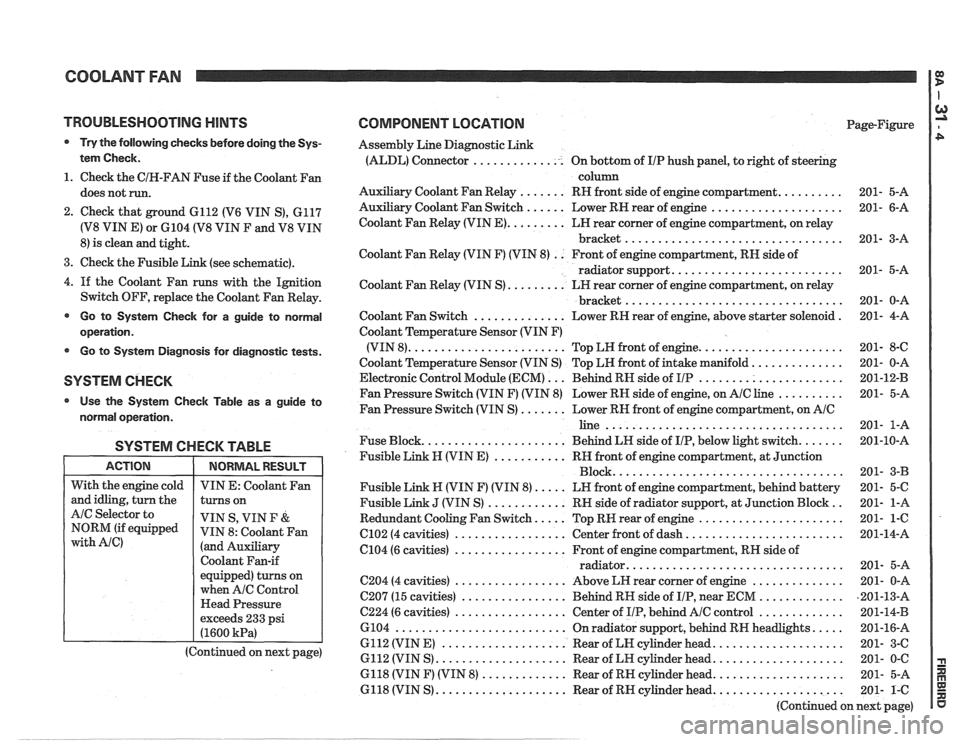
COOLANT FAN I g
TROUBLESHOOTING HINTS
@ Try the following checks before doing the Sys-
tem Check.
1. Check the CIH-FAN Fuse if the Coolant Fan
does not run.
2. Check that ground 6112 (V6 VIN S), 6117
(V8 VIN E) or 6104 (V8 VIN F and V8 VIN
8) is clean and tight.
3. Check the Fusible Link (see schematic).
4.
If the Coolant Fan runs with the Ignition
Switch OFF, replace the Coolant Fan Relay.
@ Go to System Check for a guide to normal
operation.
Go to System Diagnosis for diagnostic tests.
SYSTEM CHECK
Use the System Checlc Table as a guide to
normal operation.
SYSTEM CHECK TABLE
I ACTION I NORMALRESULT 1
COMPONENT LOCATION Page-Figure
Assembly Line Diagnostic Link
(ALDL) Connector .............. On bottom of IIP hush panel, to right of steering
column
Auxiliary Coolant Fan Relay
....... RH front side of engine compartment. ......... 201- 5-A
Auxiliary Coolant Fan Switch
...... Lower RN rear of engine .................... 201- 6-A
Coolant Fan Relay (VIN
E). ........ LH rear corner of engine compartment, on relay
bracket
................................. 201- 3-A
Coolant Fan Relay (VIN F) (VIN 8)
. . Front of engine compartment, RN side of
radiator support.
......................... 201- 5-A
Coolant Fan Relay (VIN S)
......... LH rear corner of engine compartment, on relay
................................. bracket 201- 0-A
Coolant Fan Switch
.............. Lower RH rear of engine, above starter solenoid . 201- 4-A
Coolant Temperature Sensor (VIN F)
(VIN 8).
....................... Top LW front of engine. ..................... 201- 8-C
Coolant Temperature Sensor (VIN S) Top LH front of intake manifold.
............. 201- 0-A
Electronic Control Module (ECM)
... Behind RN side of IIP ...................... 201-12-B
Fan Pressure Switch (VIN F) (VIN 8) Lower RH side of engine, on
AIC line .......... 201- 5-A
Fan Pressure Switch (VIN S)
....... Lower RN front of engine compartment, on AIC
line .................................... 201- 1-A
Fuse Block.
..................... Behind LN side of IIP, below light switch. ...... 201-10-A
Fusible Link
N (VIN E) ........... RH front of engine compartment, at Junction
Block ................................... 201- 3-B
Fusible Link N (VIN F) (VIN 8).
.... LN front of engine compartment, behind battery 201- 5-C
Fusible Link
J (VIN S) ............ RN side of radiator support, at Junction Block .. 201- 1-A
Redundant Cooling Fan Switch.
.... Top RW rear of engine ...................... 201- 1-6
C102 (4 cavities) ................. Center front of dash. ....................... 201-14-A
6104 (6 cavities)
................. Front of engine compartment, RH side of
................................ radiator. 201- 5-A
C204 (4 cavities) ................. Above LH rear corner of engine .............. 201- 0-A
C207 (15 cavities)
................ Behind RH side of IIP, near ECM ............. ,201-13-A
C224 (6 cavities) ................. Center of IIP, behind AIC control ............. 201-14-B
6104
.......................... On radiator support, behind RN headlights. .... 201-16-A
6112 (VIN E)
................... Rear of LN cylinder head. ................... 201- 3-C
6112 (VIN S)
.................... Rear of LH cylinder head. ................... 201- 0-C
6118 (VIN F) (VIN 8)
............. Rear of RH cylinder head. ................... 201- 5-A
6118 (VIN S)
.................... Rear of RH cylinder head. ................... 201- 1-C
(Continued on next page)
With
the engine cold
and idling, turn the
AIC Selector to
NORM (if equipped
with Ale)
VIN E: Coolant Fan
turns on
VIN S, VIN
F &
VIN 8: Coolant Fan
(and Auxiliary
Coolant Fan-if
equipped) turns on
when
A/C Control
Head Pressure
exceeds 233 psi
(1600
kPa)
(Continued on next page)
Page 1310 of 1825
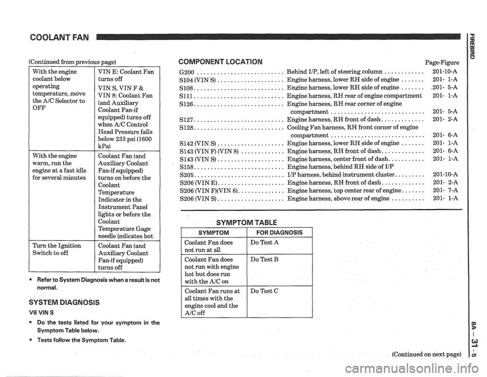
COOLANT FAN
With the engine
warm, run the
engine at a fast idle
for several minutes
(Continued
from previous page)
Switch to off
With
the engine
coolant below
operating
temperature, move
the AlC Selector to
OFF
Coolant Fan (and
Auxiliary Coolant
Fan-if equipped)
turns on before the
Coolant
Temperature
Indicator in the
Instrument Panel
lights or before the
Coolant
Temperature Gage
needle indicates hot
Coolant Fan (and
Auxiliary Coolant
Fan-if equipped)
turns off
VIN E:
Coolant Fan
turns off
VIN S, VIN F
&
VIN 8: coolant Fan
(and ~~~ili~~~
Coolant Fan-if
equipped) turns off
when
A/C Control
Head Pressure falls
below 233 psi (1600
kPa)
- -
* Refer to System Diagnosis when a result is not
normal.
SYSTEM DIAGNOSIS
V6 VIN S
* Do the tests listed for your symptom in the
Symptom Table below.
@ Tests follow the Symptom Table.
COMPONENT LOCATION Page-Figure
.......................... ............ 6-200 Behind IIP, left of steering column 201-10-A
....... .................... S104 (VIN S) Engine harness,
lower RN side of engine 201- l-A
....... .......................... S108. Engine harness, lower RN side of engine .201- 5-A
........................... S111 Engine harness, RR rear of engine compartment 201- l-A
.......................... S126. Engine harness, RR rear corner of engine
............................ compartment 201- 5-A
.......................... ............ S127. Engine harness, RH front of dash. 201- 2-A
.......................... S128. Cooling Fan harness, RN front corner of engine
............................ compartment 201- 6-A
.................... S142 (VIN S) Engine harness, lower RR side of engine ....... 201- l-A
............ S143 (VIN F) (VIN 8) ............. Engine harness, RH front of dash. 201- 6-A
.................... S143 (VIN S) Engine
harness, center front of dash. .......... 201- l-A
.......................... S158. Engine harness, behind RH side of IIP
.......................... S205. I/P harness, behind instrument cluster. ........ 201-10-A
S206 (VIN E)
.................... Engine harness, RH front of dash. ............ 201- 2-A
S206 (VIN
F)(VIN 8). ............. Engine harness, top center rear of engine. ...... 201- 7-A
.................... S206 (VIN S) Engine harness, above rear of engine .......... 201- 1-A
SYMPTOM TABLE
all times with the
engine cool and the
SYMPTOM
Coolant Fan does
not
run at all
Coolant Fan does
not run with engine
hot but does
run
with the A/C on
(Continued on next page)
FOR DIAGNOSIS
Do Test A
Do Test B