PONTIAC FIERO 1988 Service Repair Manual
Manufacturer: PONTIAC, Model Year: 1988, Model line: FIERO, Model: PONTIAC FIERO 1988Pages: 1825, PDF Size: 99.44 MB
Page 1311 of 1825
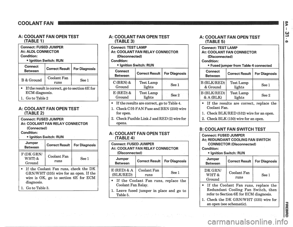
COOLANT FAN 1:
0 If the result is correct, go to section 6E for
ECM diagnosis.
1. Go to Table 2
A: COOLANT FAN OPEN TEST
(TABLE
1 )
Connect: FUSED JUMPER
At: ALDL CONNECTOR
Condition:
@ lgnition Switch: RUN
A: COOLANT FAN OPEN TEST
(TABLE
2)
At: COOLANT FAN RELAY CONNECTOR
(Connected)
Condition:
0 lgnition Switch: RUN
Connect
Between
B & Ground
Jumper Correct Result For Diagnosis
Between
(DK GRN/ Coolant Fan
WHT) & See 1
1 Ground 1 runs 1 1
Correct Result
Coolant Fan
runs
If the Coolant Fan runs, check the DK
GRNIWNT (335) wire for an open. If the
wire is OK, go to section 6E for ECM
diagnosis.
1. Go to Table 3.
For Diagnosis
See 1
A: COOLANT FAN OPEN TEST
(TABLE
3)
Connect: TEST LAMP
At: COOLANT FAN RELAY CONNECTOR
(Disconnected)
Condition:
0 lgnition Switch: RUN
Connect Correct Result For Diagnosis
Between
lights
0 If the results are correct, go to Table 4.
1. Check CIN-FAN Fuse and BRN (250) wire
for open.
2. Check Fusible Link J and RED (2) wire for
opens.
A: COOLANT FAN OPEN TEST
(TABLE
4)
Connect: FUSED JUMPER
At: COOLANT FAN RELAY CONNECTOR
(Disconnected)
Jumper Correct Result For Diagnosis
Between
(BLKIRED)
If the Coolant Fan runs, replace the
Coolant Fan Relay.
1. Leave fused jumper in place and go to
I Table 5.
A: COOLANT FAN OPEN TEST
(TABLE
5)
B: COOLANT FAN SWITCH TEST
Connect: TEST LAMP
At: COOLANT FAN CONNECTOR
(Disconnected)
Condition:
Fused jumper from Table
4 connected
Connect
Between
B (BLKIRED)
& Ground
B (BLKIRED)
& A (BLK)
Connect: FUSED JUMPER
At; REDUNDANT COOLING FAN
SWITCH
CONNECTOR (Disconnected)
Condition:
@ lgnition Switch: RUN
If the results are correct, replace the
Coolant Fan.
1. Check BLKIRED (532) wire for an open.
2. Check BLK (150) wire for an open.
Correct Result
Test Lamp
lights
Test Lamp lights
Jumper
Between
WHT &
Ground
For Diagnosis
See 1
See 2
@ If the Coolant Fan runs, replace the
Redundant Cooling Fan Switch, then
refer to Section 6E for ECM diagnosis.
1. Check the DK GRNIWNT (335) wire for
an open (see schematic).
Correct Result
Coolant Fan
runs
For Diagnosis
See 1
Page 1312 of 1825
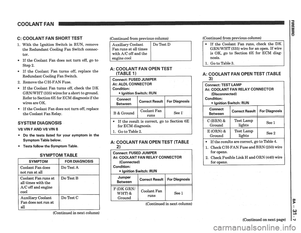
COOLANT FAN rn
6: COOLANT FAN SHORT TEST
1. With the Ignition Switch in RUN, remove
the Redundant Cooling Fan Switch connec-
tor.
If the Coolant Fan does not turn off, go to
Step
2.
If the Coolant Fan turns off, replace the
Redundant Cooling Fan Switch.
2. Remove the CIR-FAN Fuse.
If the Coolant Fan turns off, check the DK
GRNIWHT
(335) wires for a short to ground.
Refer to Section 6E for ECM diagnosis if the
wires are OK.
a If the Coolant Fan does not turn off, replace
the Coolant Fan Relay.
SYSTEM DlAGNOSlS
V8 VIN F AND V8 VIN 8
Do the tests listed for your symptom in the
Symptom Table below.
Tests follow the Symptom Table.
SYMPTOM TABLE
I SYMPTOM I FORDIAGNOSIS I
I Do Test A I
I not run at aB I I
Coolant Fan runs at
all times with the
A/C off and engine
cool
(Continued in next column)
Do
Test
B
Auxiliary Coolant
Fan does not run at
all
:Continued from previous column)
Fan runs at
all times
with
AIC off and the
Do Test C (Continued
from previous column)
GRNIWNT
(335) wire for an open. If wire
is OK, go to Section 6E for ECM diag-
nosis.
1. Go to Table 3.
A: COOLANT FAN OPEN TEST
(TABLE
1)
At: ALDL CONNECTOR
Condition:
I B &Ground I I See l' I
Connect
Between
If the result is correct, go to Section 6E
for ECM diagnosis.
A: COOLANT FAN OPEN TEST (TABLE
2)
Correct Result
I
Connect: FUSED JUMPER
At: COOLANT FAN RELAY CONNECTOR For
Diagnosis
(Connected)
Condition: lgnition Switch: RUN
Jumper
I Correct Result I For Diagnosis I Between
(DK GRN1 Coolant Fan
WHT) & See 1
1 Ground 1 runs 1 1
A: COOLANT FAN OPEN TEST (TABLE
3) I
Connect: TEST LAMP
At: COOLANT FAN RELAY CONNECTOR
(Disconnected)
Condition:
Connect I Correct Rewn I For Diagnosis I I Between
C (BRN) &
Ground
If the results are correct, go to Table
4.
1. Check CIH-FAN Fuse and BRN (250) wire
for opens.
2. Check Fusible Link H and ORN (440) wire
for opens.
E (ORN)
&
Ground
(Continued in next column)
(Continued on next page)
Test Lamp
lights See
1
Test
Lamp
lights See 2
Page 1313 of 1825
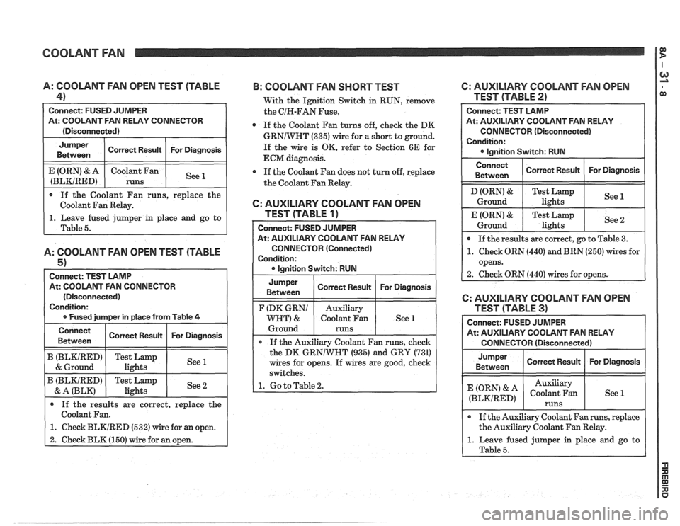
COOLANT FAN
0 If the Coolant Fan runs, replace the
Coolant Fan Relay.
A: COOLANT FAN OPEN TEST (TABLE
4)
Connect: FUSED JUMPER
At: COOLANT FAN RELAY CONNECTOR
(Disconnected)
1. Leave fused jumper in place and go to
Table
5.
A: COOLANT FAN OPEN TEST (TABLE
5 1
Connect: TEST LAMP
At: COOLANT FAN CONNECTOR
(Disconnected)
Condition:
0 Fused jurnper in place from Table 4
For Diagnosis
See 1
Jumper
Between
E (ORN) & A
(BLKIRED)
Connect Correct Result For Diagnosis
Betvveen Correct
Result
coolant an
runs
B (BLKIRED) Test Lamp
1 & Ground 1 lights I See1
B (BLKIRED) Test Lamp
& A (BLK) I lights
If the results are correct, replace the
Coolant Fan.
1. Check BLKIRED (532) wire for an open.
2. Check BLK (150) wire for an open.
B: COOLANT FAN SHORT TEST 6: AUXILIARY COOLANT FAN OPEN
With the Ignition Switch in RUN, remove TEST (TABLE 2)
the CIH-FAN Fuse.
0 If the Coolant Fan turns off, check the DK
GRNIWNT (335) wire for a short to ground.
If the wire is OK, refer to Section 6E for
ECM diagnosis.
If the Coolant Fan does not turn off, replace
the Coolant Fan Relay.
6: AUXILIARY COOLANT FAN OPEN
TEST (TABLE
1)
Connect: FUSED JUMPER
At: AUXILIARY COOLANT FAN RELAY
CONNECTOR (Connected)
Condition:
0 Ianition Switch: RUN Connect:
TEST LAMP
At: AUXILIARY COOLANT
FAN RELAY
CONNECTOR (Disconnected)
Condition: Ignition Switch: RUN
Connect
Between
D (ORN) &
Ground
E (ORN)
&
Ground
Jumper
Between
If the Auxiliary Coolant Fan runs, check
the DK
GRNlWNT (935) and GRY (731)
wires for opens. If wires are good, check
switches.
1. Go to Table 2.
F (DK GRNl
WHT) &
Ground If
the results are correct, go to Table
3.
1. Check ORN (440) and BRN (250) wires for
opens.
2. Check ORN
(440) wires for opens.
Correct Result
Test Lamp
lights
Test Lamp lights
Correct Result For
Diagnosis
See 1
See 2
Auxiliary
Coolant Fan
runs
Connect: FUSED JUMPER
At: AUXILIARY COOLANT FAN RELAY
CONNECTOR (Disconnected)
For
Diagnosis See 1
Jumper
Between
(ORN' & A
(BLKIRED)
6: AUXILIARY COOLANT FAN OPEN
0 If the Auxiliary Coolant Fan runs, replace
the Auxiliary Coolant Fan Relay.
1. Leave fused jumper in place and go to
Table
5.
Correct Result
Auxiliary
Coolant Fan
runs
For Diagnosis
See 1
Page 1314 of 1825
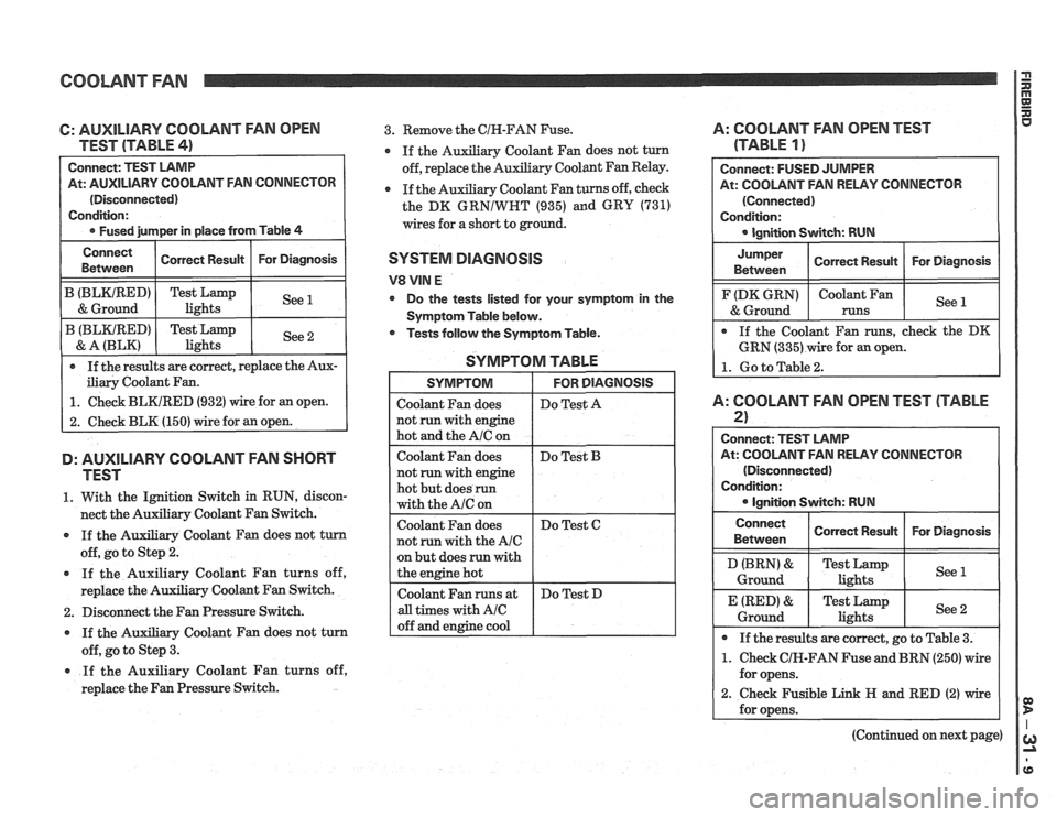
COOLANT FAN
C: AUXILIARY COOLANT FAN OPEN
TEST (TABLE
41
At: AUXILIARY COOLANT FAN CONNECTOR
(Disconnected)
iliary Coolant Fan.
1. Check BLKIRED (932) wire for an open.
2. Check BLK (150) wire for an open.
D: AUXILIARY COOLANT FAN SHORT
TEST
1. With the Ignition Switch in RUN, discon-
nect the Auxiliary Coolant Fan Switch.
If the Auxiliary Coolant Fan does not turn
off, go to Step
2.
If the Auxiliary Coolant Fan turns off,
replace the Auxiliary Coolant Fan Switch.
2. Disconnect the Fan Pressure Switch.
If the Auxiliary Coolant Fan does not turn
off, go to Step
3.
* If the Auxiliary Coolant Fan turns off,
replace the Fan Pressure Switch.
3. Remove the CIN-FAN Fuse. A: COOLANT FAN OPEN TEST
y Coolant Fan does not turn (TABLE 1 )
Auxiliary Coolant Fan Relay.
Coolant Fan turns off, check
the DK
GRNIWRT (935) and GRY (731)
wires for a short to ground.
SYSTEM DIAGNOSIS
V8 VIN E
Do the tests listed for your symptom in the
Symptom Table below.
* Tests follow the Symptom Table.
SYMPTOM TABLE
but does run with
At: COOLANT FAN RELAY CONNECTOR
A: COOLANT FAN OPEN TEST (TABLE
2)
Connect: TEST LAMP
At: COOLANT FAN RELAY CONNECTOR
(Disconnected)
Condition:
Ignition Switch: RUN
Connect
Between
I Conen Resun I For Diagnosis I
Ground lights
* If the results are correct, go to Table 3.
1. Check CIK-FAN Fuse and BRN (250) wire
for opens.
2. Check Fusible Link H and RED (2) wire
(Continued on next page)
Page 1315 of 1825
COOLANT FAN I $
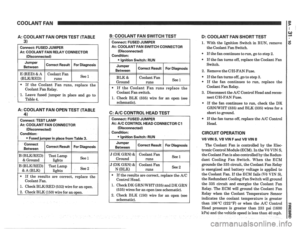
A: COOLANT FAN OPEN TEST (TABLE
3)
Connect: FUSED JUMPER
At: COOLANT FAN RELAY CONNECTOR
(Disconnected)
Jumper Correct Result For Diagnosis
Between
1. Leave fused jumper in place and go to
Table
4.
E (RED) & A
(BLKIRED)
A: COOLANT FAN OPEN TEST (TABLE
41
Connect: TEST LAMP
At: COOLANT FAN CONNECTOR
(Disconnected)
Condition:
Fused jumper in place from Table
3.
If the Coolant Fan runs, replace the
Coolant Fan Relay. Coolant
Fan
runs
-. -. See --
B: COOLANT FAN SWITCH TEST
Connect
Between
B (BLKtRED)
& Ground
B (BLKIRED)
& A (BLK)
Connect: FUSED JUlVlPER
At: COOLANT FAN SWITCH CONNECTOR
(Disconnected)
Condition: lgnition Switch: RUN
Jumper
Between Correct
Result For Diagnosis
Coolant Fan
Ground
runs
If the Coolant Fan runs replace the
Coolant Fan switch.
1. Check BLK (335) wire for an open (see
schematic).
6: AIC CONTROL HEAD TEST
If the results are correct, replace the
Coolant Fan.
1. Check BLKIRED (532) wire for an open.
2. Check BLK (150) wire for an open.
Correct Result
Test Lamp
lights
Test Lamp
lights
Connect: FUSED JUMPER
At:
A/C CONTROL HEAD CONNECTOR Cl
(Disconnected)
Condition:
lgnition Switch: RUN
For Diagnosis
See 1
See 2
Jumper
Between I Correct Result I For Diagnosis I
".' Ground
J (DK GRN) & Coolant Fan See N (BLK) runs
If the results are correct, replace the
AIC
Control Head.
1. Check DK GRNIWHT (335) and DK GRN
(535) wires for an open (see schematic).
2. Check BLK (150) wire for an open (see
schematic).
D: COOLANT FAN SHORT TEST
1. With the Ignition Switch in RUN, remove
the Coolant Fan Switch.
If the fan continues to
run, go to step 2.
If the fan turns off, replace the Coolant Fan
Switch.
2. Remove the CIH-FAN Fuse.
If the fan turns off, go to step 3.
If the fan continues to run, replace the
Coolant Fan Relay.
3. Disconnect the
AIC Control Head and recon-
nect CIH-FAN Fuse.
If the fan continues to run,
check the DK
GRNIWHT (335) and BLK (335) wires for a
short to ground.
If the fan turns off, replace the
AIC Control
Head.
CIRCUIT OPERATION
V6 VIN S, V8 VIN F and V8 VIN 8
The Coolant Fan is controlled by the Elec-
tronic Control Module (ECM). In the V6 VIN S,
the Coolant Fan is also controlled by the Redun-
dant Cooling Fan Switch. When the ECM
grounds the 335 circuit, the Coolant Fan Relay
is energized and battery voltage is applied to
the Coolant Fan.
If the ECM fails (V6 VIN S),
the Redundant Cooling Fan Switch will ground
the 335 circuit and energize the Coolant Fan
Relay. The ECM will ground the Coolant Fan
Relay when the Coolant Temperature Sensor
indicates the coolant temperature is greater
than 106
OC (222 OF) or when the AIC Control
Head pressure is greater than 233 psi (1600
kPa) and the vehicle speed is less than 40 mph.
Page 1316 of 1825
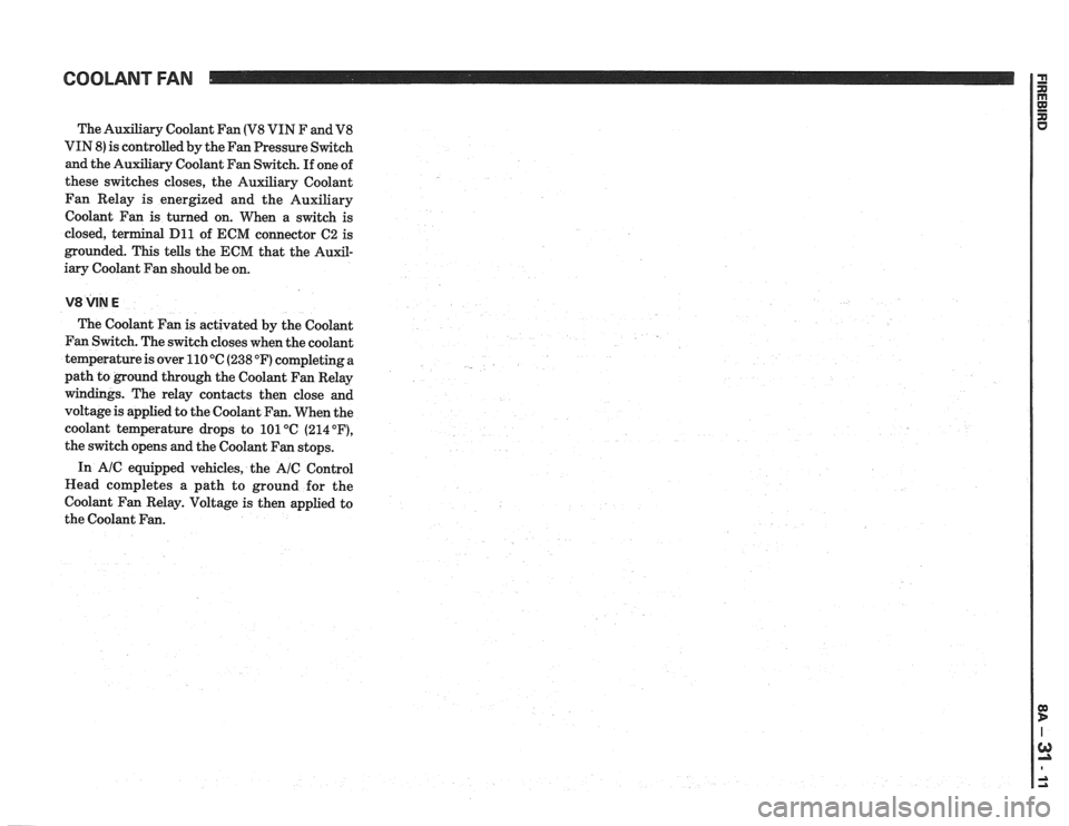
The Auxiliary Coolant Fan (V8 VIN F and V8
VIN 8) is controlled by the Fan Pressure Switch
and the Auxiliary Coolant Fan Switch. If one of
these switches closes, the Auxiliary Coolant
Fan Relay is energized and the Auxiliary
Coolant Fan is turned on. When a switch is
closed, terminal
Dl1 of ECM connector C2 is
grounded. This tells the ECM that the Auxil-
iary Coolant Fan should be on.
V8 VIN E
The Coolant Fan is activated by the Coolant
Fan Switch. The switch closes when the coolant
temperature is over 110
"C (238 OF) completing a
path to ground through the Coolant Fan Relay
windings. The relay contacts then close and
voltage is applied to the Coolant Fan. When the
coolant temperature drops to 101°C
(214"F),
the switch opens and the Coolant Fan stops.
In
AIC equipped vehicles, the AIC Control
Head completes a path to ground for the
Coolant Fan Relay. Voltage is then applied to
the Coolant Fan.
Page 1317 of 1825
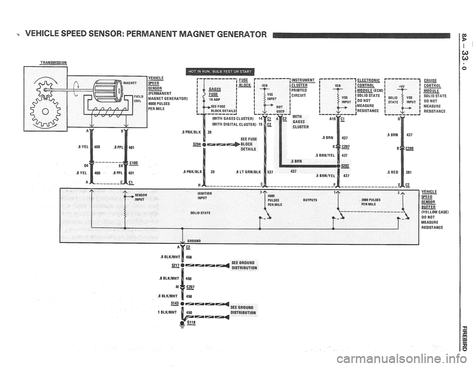
VEHICLE SPEED SENSOR: PERMANENT MAGNET GENERATOR
ELECTRONIC
CONTROL
MODULE (ECM
SOLID STATE
DO NOT
MEASURE RESISTANCE CRUISE
- CONTROL
MODULE
SOLID SFATE DO NOT
MEASURE RESISTANCE
Page 1318 of 1825
VEHICLE SPEED SENSOR
TROUBLESHOOTING HINTS
0 Try the following checks before doing the
System Diagnosis
.
1
. Check the Gages Fuse by observing the Brake
Indicator when applying the Parking Brake
wrth the Ignition Switch in RUN (engine not
running)
.
2 . Check ground 6118 .
3 . If only the Speedometer or only the Odometer
does not work. replace the suspect item
.
Go to System Diagnosis for diagnostic tests .
SYSTEM DlAGNOSlS
Do the tests listed for your symptom in the
Symptom Table below
.
Tests follow the Syrnptom Table .
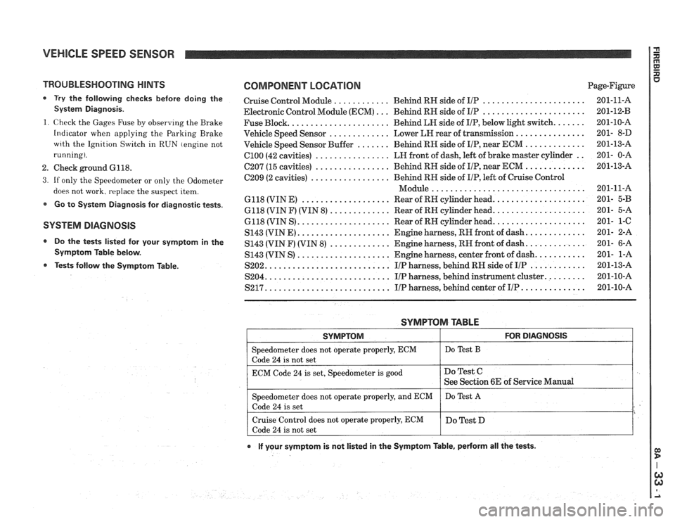
COMPONENT LOCATION Page-Figure
Cruise Control Module
............ Behind RN side of IlP ...................... 201-11-A
Electronic Control Module (ECM)
... Behind RN side of IIP ...................... 201-12-B
Fuse Block
...................... Behind LN side of IIP. below light switch ....... 201-10-A
Vehicle Speed Sensor
............. Lower LEI rear of transmission ............... 201- 8-D
Vehicle Speed Sensor Buffer
....... Behind RH side of IIP. near ECM ............. 201-13-A
ClOO (42 cavities) ................ LN front of dash. left of brake master cylinder .. 201- 0-A
C207 (15 cavities) ................ Behind RH side of IIP. near ECM ............. 201-13-A
C209 (2 cavities)
................. Behind RN side of IIP. left of Cruise Control
................................. Module 201-11-A
6118 (VIN E)
................... Rear of RH cylinder head .................... 201- 5-B
6118 (VIN F) (VIN 8) ............. Rear of RN cylinder head .................... 201- 5-A
6118 (VIN S)
.................... Rear of RN cylinder head .................... 201- 1-C
S143 (VINE)
.................... Engine harness. RH front of dash ............. 201- 2-A
S143 (VIN F) (VIN
8) ............. Engine harness. RN front of dash ............. 201- 6-A
S143 (VIN S)
.................... Engine harness. center front of dash ........... 201- 1-A
S202
........................... IIP harness. behind RH side of IIP ............ 201-13-A
S204
........................... IIP harness. behind instrument cluster ......... 201-10-A
S217 ........................... IIP harness. behind center of IIP .............. 201-10-A
SYMPTOM TABLE
I SYMPTOM I FOR DIAGNOSIS I
=liter does not operate properly. ECM I Do Test B
code 24 is not set
ECM Code
24 is set. Speedometer is good
e If your symptom is not listed in the Symptom Table. pedorm all the tests .
Do Test C
See Section 6E of Service Manual
Speedometer does not operate properly. and ECM
Code
24 is set
Cruise Control does not operate properly. ECM
Code
24 is not set Do
Test
A
Do Test D
Page 1319 of 1825
VEHICLE SPEED SENSOR
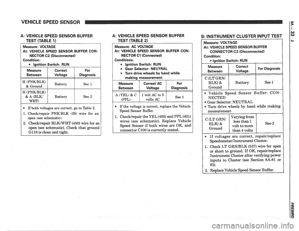
A: VEHICLE SPEED SENSOR BUFFER
TEST (TABLE
1)
At: VEHICLE SPEED SENSOR BUFFER CON-
NECTOR
62 (Disconnected)
Condition:
I e lnnition Switch: RUN I
I ztmz) I Battery I See 1 /
Measure
Between
A: VEHICLE SPEED SENSOR BUFFER
TEST (TABLE
2)
Measure: AC VOLTAGE
At: VEHICLE SPEED SENSOR BUFFER CON-
NECTOR Cl (Connected)
Conditions:
e Ignition Switch: RUN
e Gear Selector: NEUTRAL
e Turn drive wheels by hand while
making measurement
Measure
I Correct AC 1 For
Correct
Voltage
H (PNKJBLK)
& A (BLKJ
WNT)
B: INSTRUMENT CLUSTER INPUT TEST I
For
Diagnosis Measure:
VOLTAGE
At: VEHICLE SPEED SENSOR BUFFER
CONNECTOR C2 (Disconnected)
Condition: lgnition Switch: RUN
* If both voltages are correct, go to Table 2.
1. Checklrepair PNKJBLK (39) wire for an
open (see schematic).
2.
ChecWrepair BLKIWHT (450) wire for an
open (see schematic). Check that ground
6118 is clean and tight. Battery
See
2
Measure
Between Correct I For Diagnosis I I Voltage
Between
A (YEL) & C
(PPL)
( CgEg?' I Battery I See 1
e If the voltage is correct, replace the Vehicle
Speed Sensor Buffer.
1.
ChecWrepair the UEL (400) and PPL (401)
wires (see schematic). Replace Vehicle
Speed Sensor if both wires are OK, and
connector
C100 is correctly mated.
Voltage
1 volt AC to 5
volts
AC
Ground I
Vehicle Speed Sensor Buffer: CON-
NECTED
Gear Selector: NEUTRAL
Diagnosis
See
I 0 Turn drive wheels by hand while making I
measurement
I
If voltages are correct, repairlreplace
SpeedometerIInstrument Cluster.
1. Check LT GRNIBLK (537) wire for open
or short to ground. If OK,
repairireplace
Instrument Cluster after verifying power
inputs to Cluster (see Section
8A-81 or
82).
2. Replace Vehicle Speed Sensor Buffer.
(LT GRN1
BLK' &
Ground
Varying from
less than
5.
volt to more
than 4 volts See 2
Page 1320 of 1825
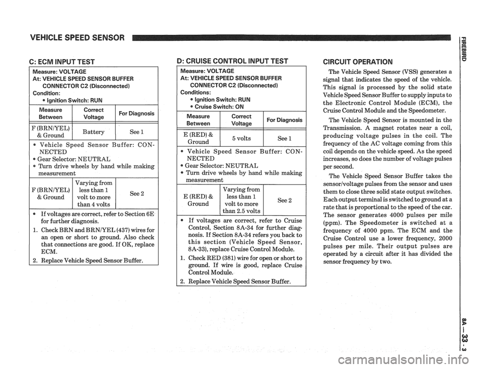
VEHICLE SPEED SENSOR
C: ECM INPUT TEST
At: VEHICLE SPEED SENSOR BUFFER
CONNECTOR
62 (Disconnected)
Gear Selector: NEUTRAL
1. Check BRN and
BRNIYEL (437) wires for
an open or short to ground. Also check
that connections are good. If
OK, replace
1 2. Replace Vehicle Speed Sensor Buffer.
At: VEHICLE SPEED SENSOR BUFFER
CONNECTOR
C2 (Disconnected)
Gear Selector: NEUTRAL
nosis. If Section 8A-34 refers you back to
this section (Vehicle Speed Sensor,
8A-33), replace Cruise Control Module.
1. Check RED (381) wire for open or short to
ground. If wire is good, replace Cruise
Control Module.
D: CRUISE CONTROL lNPUT TEST CIRCUIT OPERATION
The Vehicle Speed Sensor (VSS) generates a
signal that indicates the speed of the vehicle.
This signal is processed by the solid state
Vehicle Speed Sensor Buffer to supply inputs to
the Electronic Control Module (ECM), the
Cruise Control Module
and the Speedometer.
The Vehicle Speed Sensor is mounted in the
Transmission.
A magnet rotates near a coil,
producing voltage pulses in the coil. The
frequency of the AC voltage coming from this
coil depends on the vehicle speed. As the speed
increases, so does the number of voltage pulses
per second.
The Vehicle Speed Sensor Buffer takes the
sensorlvoltage pulses from the sensor and uses
them to close three solid state output switches.
Each output terminal is switched to ground at a
rate that is proportional to the speed of the car.
The sensor generates 4000 pulses per mile
(ppm). The Speedometer is switched at
a
frequency of 4000 ppm. The ECM and the
Cruise Control use a lower frequency, 2000
pulses per mile. Their output pulses are
operated by a circuit after it has divided the
sensor frequency by two.