RENAULT KANGOO 1997 KC / 1.G Engine And Peripherals Manual Online
Manufacturer: RENAULT, Model Year: 1997, Model line: KANGOO, Model: RENAULT KANGOO 1997 KC / 1.GPages: 208
Page 81 of 208
FUEL SUPPLY
Fuel cut off in case of an impact
13
OBJECTIVE
The main function of this feature is to avoid any
fires that may result from the leakage of fuel du-
ring an accident. In order to achieve this, all
components pumping fuel from the fuel tank will
automatically stop functioning during and imme-
diately after the impact. They can then only be
made to operate again by a mechanical action car-
ried out by the driver or the repairer.
DESCRIPTION
The system consists simply of an inertia switch (1),
which:
- detects the impact,
- and thus cuts off the electrical circuit.
13051R
This is fitted:
• in petrol engines, between track 1 of the
pump relay (236) and the + 12 V supply ,
• in diesel engines, between the + supply and
the electrical solenoid (or the coded solenoid
valve if the vehicle is fitted with an engine im-
mobiliser).
OPERATING PRINCIPLE
During the impact, the ball of the inertia switch
moves up and interrupts the electrical connec-
tion.
In petrol engines, the + supply of the pump relay
control circuit (236) is cut. Neither the pump or
the injectors will receive any further supply of
electricity .
The fuel contained in the tank is actually isolated.
In diesel engines, the + supply of the electrical
solenoid or of the coded solenoid is cut off.
The pump can no longer take in fuel, and there is
no longer any high pressure. All risk of fire due to
the outlet of diesel fuel at high pressure onto the
engine is removed.
RESETTING AND OPERATING THE SWITCH
In order to reset the inertia switch, it is sufficient
to press it down in order to replace the ball bea-
ring in its original position .
IMPORTANT: for petrol engines, , having reset
the switch, it is
VITAL to erase the memory of the
computer, using the
XR25. The injection compu-
ter will memorise a pump relay fault once the
system has gone into operation .
13-1
Page 82 of 208
FUEL SUPPLY
Injector gallery
13
IMPORTANT: during the opening of the fuel cir-
cuit , be sure to use a cloth to avoid possible pro-
jections of fuel due to the residual pressure.
REMOVAL
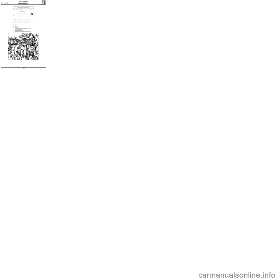
Disconnect :
- the battery,
- the pressure measurement pipe (1) of the
pressure regulator,
- the fuel return pipe (2),
- the electrical connector of the injectors (3)
99937R3
SPECIAL TOOLING REQUIRED
Mot. 1311-06 Tool for removing the fuel
supply unions
Bolt mounting injector gallery on manifold 1
TIGHTENING TORQUES (in daN.m)
D7F Engine
13-2
Page 83 of 208
FUEL SUPPLY
Injector gallery
13
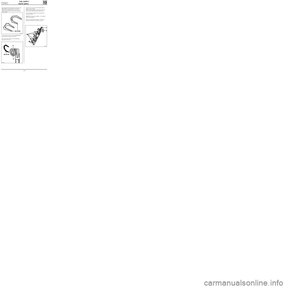
To disconnect the unions, slip tool Mot. 1311-06
between the two stems (A) and (B).
Press on the tool to lift the two retaining clips,
then pull on the union.
Remove the two bolts (5) mounting the injector
gallery on the manifold.
Slide the injector gallery, along with the injectors,
between the manifold and the cylinder head.
Extract the injector gallery from the right hand
side of the vehicle.
NOTES :The fuel pressure regulator (6) is clipped
to the injector gallery.
There is an intermediate connector (7) between
the injector connector (8) and the computer.
10046R
Disconnect the fuel supply pipe (4) using the tool
Mot. 1311-06 with the largest section (the fuel
supply pipe is equipped with a removal tool
which is attached to the connection incorporated
in the vehicle ).
99375R
99461R1
D7F Engine
13-3
Page 84 of 208
FUEL SUPPLY
Injector gallery
13
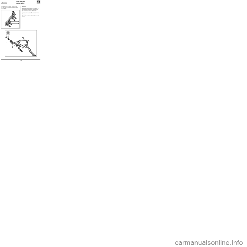
In order to extract an injector, remove the clip
(9), then press on the fastener (10) before pulling
on the injector.
PRC13.1
10047R
REFITTING
Replace the O rings at the base of the injector (if
the injector has been removed, also replace the
seal which is level with the injector head).
To ensure that the fuel supply unions are correct-
ly fastened, it is necessary to hear a"click" whilst
fastening.
For all other operations, refitting is the reverse of
removal . DF7 Engine
13-4
Page 85 of 208
FUEL SUPPLY
Injector gallery
13
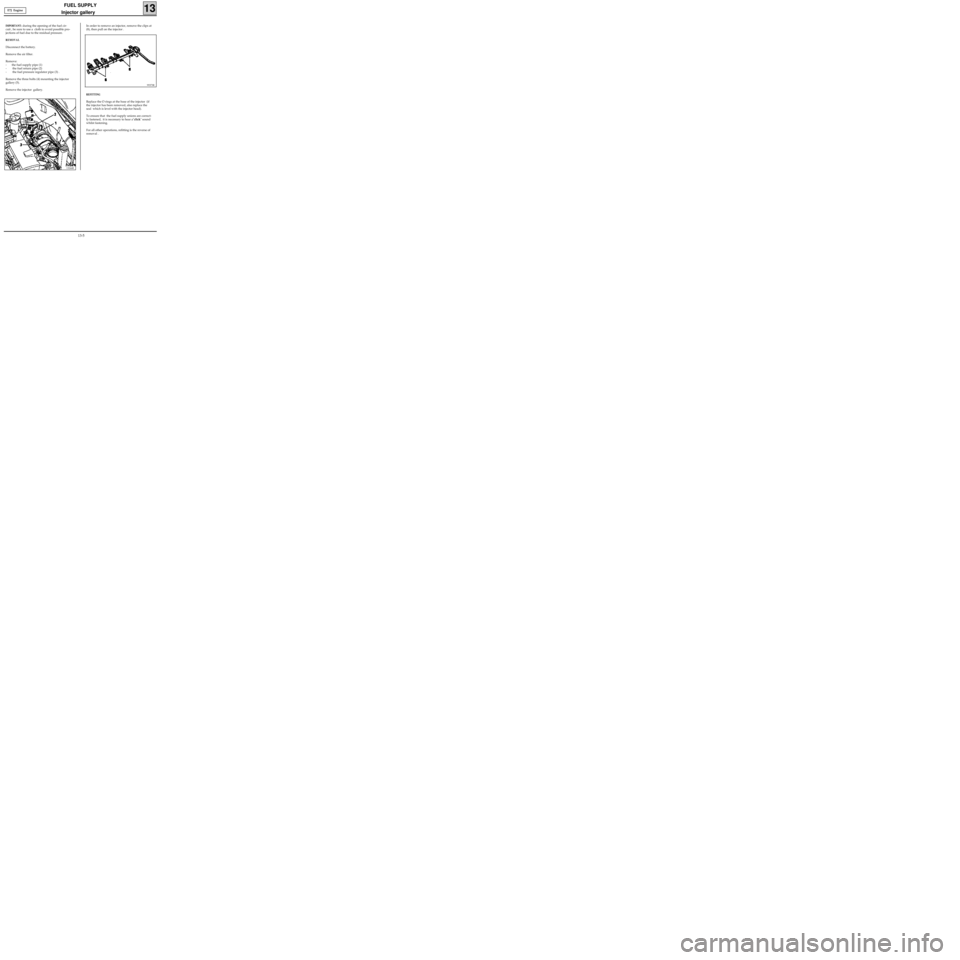
In order to remove an injector, remove the clips at
(8), then pull on the injector .
99373R
IMPORTANT: during the opening of the fuel cir-
cuit , be sure to use a cloth to avoid possible pro-
jections of fuel due to the residual pressure.
REMOVAL
Disconnect the battery.
Remove the air filter.
Remove:
- the fuel supply pipe (1)
- the fuel return pipe (2)
- the fuel pressure regulator pipe (3) .
Remove the three bolts (4) mounting the injector
gallery (5).
Remove the injector gallery.E7J Engine
13244R
REFITTING
Replace the O rings at the base of the injector (if
the injector has been removed, also replace the
seal which is level with the injector head).
To ensure that the fuel supply unions are correct-
ly fastened, it is necessary to hear a"click" sound
whilst fastening.
For all other operations, refitting is the reverse of
removal .
13-5
Page 86 of 208
FUEL SUPPLY
Fuel filter
13
LOCATION
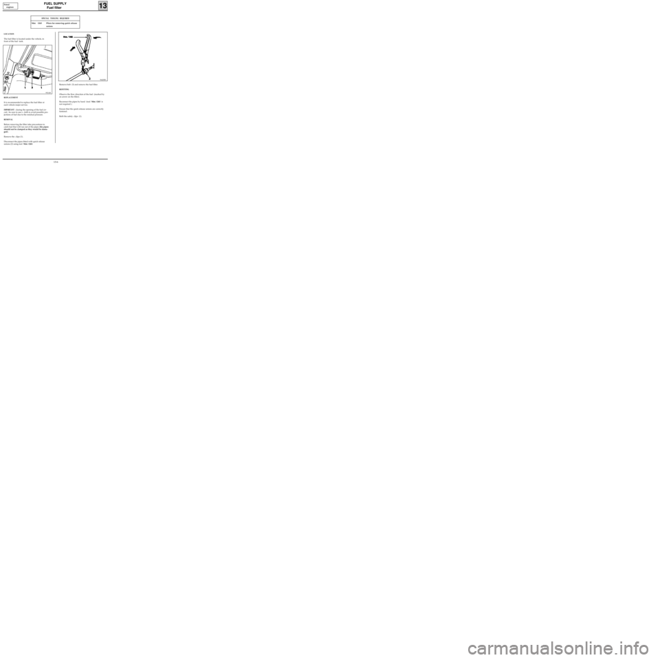
The fuel filter is located under the vehicle, in
front of the fuel tank. Petrol
engines
99214R
SPECIAL TOOLING REQUIRED
Mot. 1265 Pliers for removing quick release
unions
REPLACEMENT
It is recommended to replace the fuel filter at
each vehicle major service.
IMPORTANT : during the opening of the fuel cir-
cuit , be sure to use a cloth to avoid possible pro-
jections of fuel due to the residual pressure.
REMOVAL
Before removing the filter take precautions to
catch fuel that will run out of the pipes (the pipes
should not be clamped as they would be dama-
ged).
Remove the clips (1).
Disconnect the pipes fitted with quick release
unions (2) using tool Mot. 1265.
96420R3
Remove bolt (3) and remove the fuel filter.
REFITTING
Observe the flow direction of the fuel (marked by
an arrow on the filter).
Reconnect the pipes by hand (tool Mot. 1265 is
not required ).
Ensure that the quick release unions are correctly
fastened .
Refit the safety clips (1).
13-6
Page 87 of 208
FUEL SUPPLY
Pump flow
13
Petrol
engines
96093R2
SPECIAL TOOLING REQUIRED
Mot. 1265 Pliers for removing quick release
unions
EQUIPMENT REQUIRED
2 000 ml measuring cylinder
It is advised to check the pump supply flow
through the fuel return pipe connected to the
pump-fuel sender unit assembly.
IMPORTANT
During this operation, it is essential :
• to refrain from smoking and handling incan-
descent objects close to the working area,
• to take precautions against possible fuel
projections which may occur due to the resi-
dual pressure in the supply pipes when they
are removed.
CHECKING THE PUMP FLOW
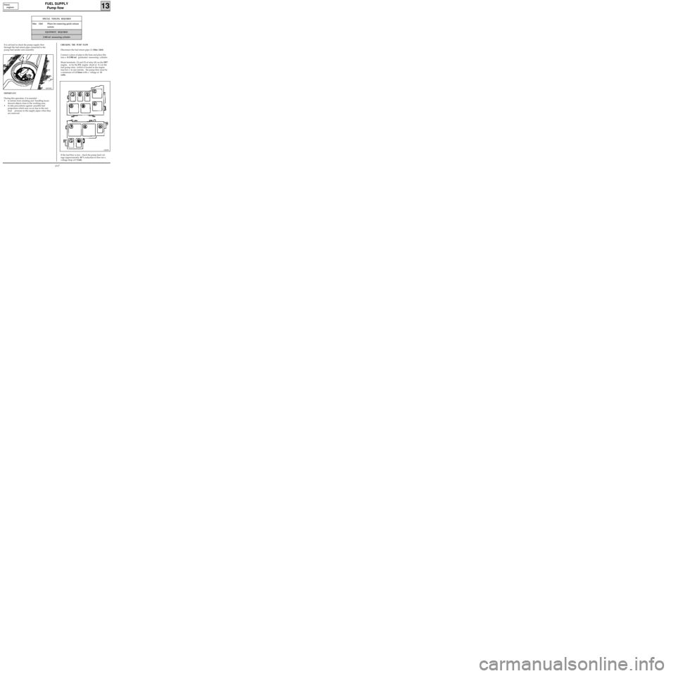
Disconnect the fuel return pipe (1) (Mot. 1265).
Connect a piece of pipe to the hose and place this
into a 0-2 000 ml graduated measuring cylinder.
Shunt terminals (3) and (5) of relay (K) on the DF7
engine, or for the
E7J engine shunt at (L) on the
fuel pump relay (which is located in the engine
fuse box ). In one minute, the pump flow must be
a minimum of 1.3 litres with a voltage of 12
volts.
If the fuel flow is low, check the pump feed vol-
tage (approximately 10 % reduction in flow for a
voltage drop of 1 Volt)
12839S
13-7
Page 88 of 208
FUEL SUPPLY
Fuel pressure
13
CHECKING THE FUEL PRESSURE
SPECIAL TOOLING REQUIRED
Mot. 1311-01 Fuel pressure test kit (with a pressure
gauge 0; + 10 bar tool kit)
Mot. 1311-05 Junction tool (for union K)
Mot. 1311-06 Tool for removing fuel supply unions
IMPORTANT : during the opening of the fuel cir-
cuit , be sure to use a cloth to avoid possible pro-
jections of fuel due to the residual pressure.
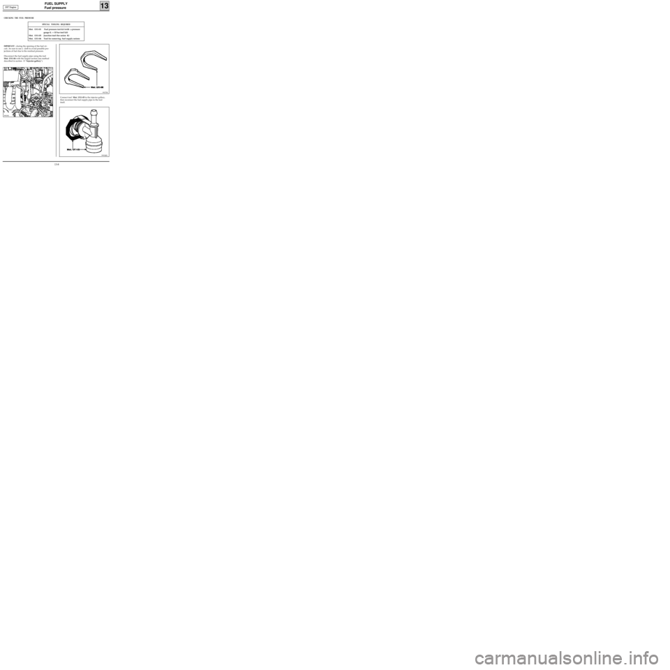
Disconnect the fuel supply pipe using the tool
Mot. 1311-06 with the largest section (see method
described in section 13 "Injector gallery").
Connect tool Mot. 1311-05 to the injector gallery,
then reconnect the fuel supply pipe to the tool
itself.
99375R
99934R1
99939S
DF7 Engine
13-8
Page 89 of 208
FUEL SUPPLY
Fuel pressure
13
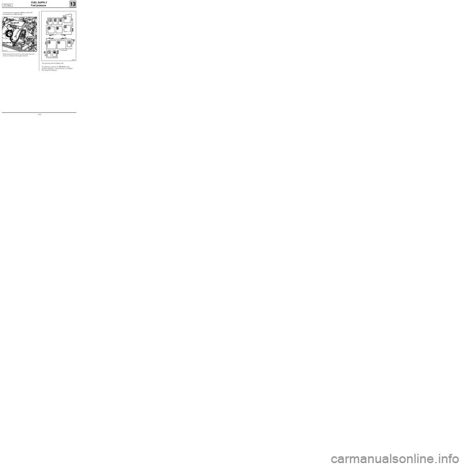
Connect pressure gauge 0 ; 10 bars along with
the flexible hose, Mot. 1311-01.
Shunt terminals (3) and (5) on the pump relay (K) ,
which is situated in the engine fuse box.
99938-1R
12839S
The pressure must be 3 bars ± 0,2.
By applying a pressure of 500 mbars to the
pressure regulator, a fuel pressure of 2.5 bars ±
0.2 should be obtained. DF7 Engine
13-9
Page 90 of 208
FUEL SUPPLY
Fuel pressure
13
CHECKING THE FUEL PRESSURE
SPECIAL TOOLING REQUIRED
Mot. 1311-01 Fuel pressure test kit (with a pressure
gauge 0; + 10 bar tool kit)
Mot. 1311-05 Junction tool (for union J)
IMPORTANT : during the opening of the fuel cir-
cuit , be sure to use a cloth to avoid possible pro-
jections of fuel due to the residual pressure.
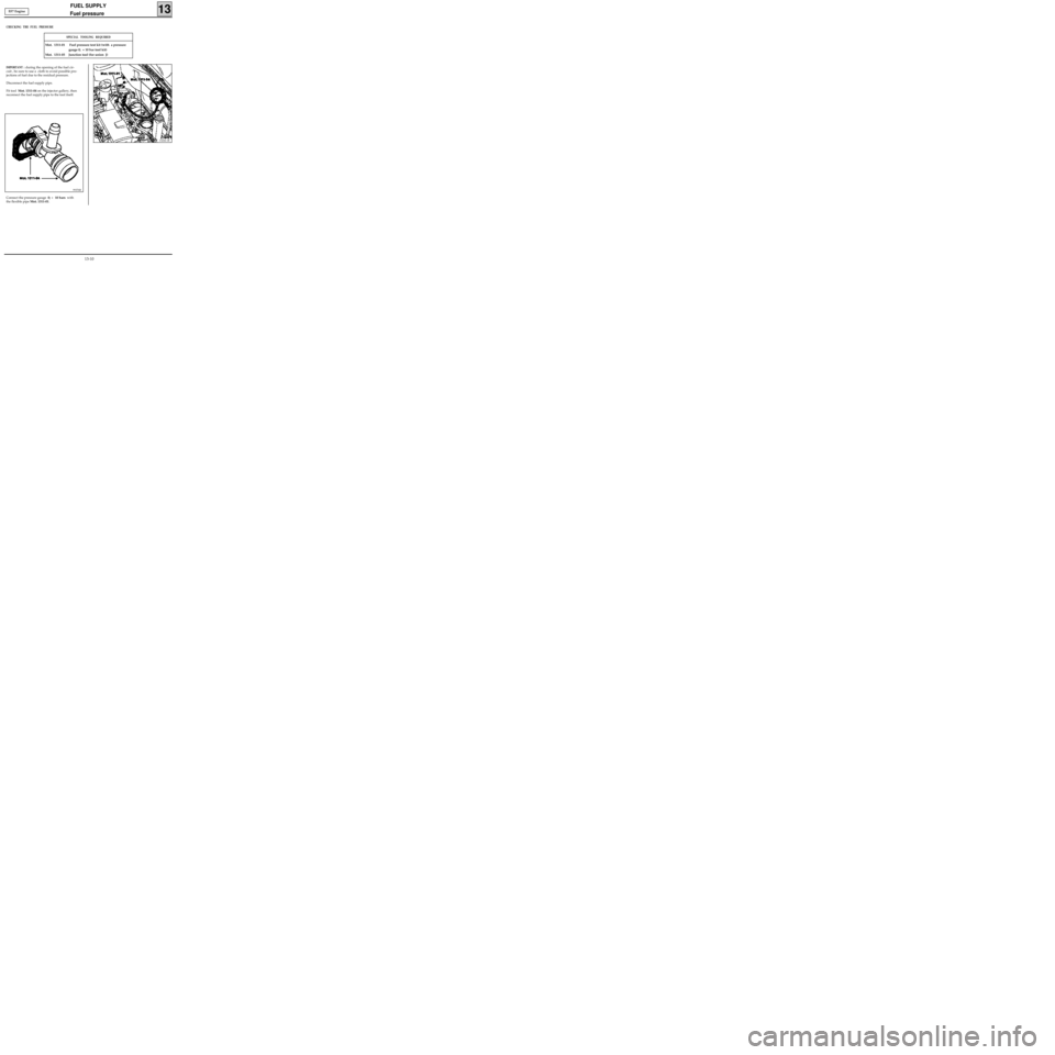
Disconnect the fuel supply pipe.
Fit tool Mot. 1311-04 on the injector gallery, then
reconnect the fuel supply pipe to the tool itself.
13244-1R
EF7 Engine
Connect the pressure gauge 0; + 10 bars with
the flexible pipe Mot. 1311-01.
99376R
13-10