RENAULT KANGOO 1997 KC / 1.G Sheet Metal Work Workshop Manual
Manufacturer: RENAULT, Model Year: 1997, Model line: KANGOO, Model: RENAULT KANGOO 1997 KC / 1.GPages: 255
Page 1 of 255
77 11 194 280JULY 1997Edition Anglaise
Sheet Metal Work
The repair methods given by the manufacturer in this document are based on the
technical specifications current when it was prepared.
The methods may be modified as a result of changes introduced by the
manufacturer in the production of the various component units and accessories
from which his vehicles are constructed."All copyrights reserved by Renault.
Copying or translating, in part or in full, of this document or use of the service part
reference numbering system is forbidden without the prior written authority of
Renault.
CRenault 1997
GENERAL
LOWER STRUCTURE
UPPER FRONT STRUCTURE
UPPER SIDE STRUCTURE
UPPER REAR STRUCTURE
TOP OF BODY
SIDE OPENING ELEMENTS
NON-SIDE OPENING ELEMENTS
Page 2 of 255
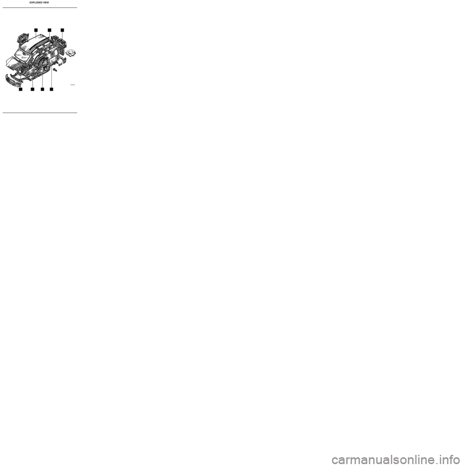
EXPLODED VIEW
PRB4008
Page 3 of 255
Contents
GENERAL
Dimensions
Engine and equipment
Identification
Means of lifting
Towing
Using symbols
Key to symbols
Description of Parts (exploded)
Opening clearances
Collision fault finding
Sub- frame dimensions
Repair bench
Special tooling
Part Number of special tooling40-1
40-2
40-4
40-6
40-8
40-9
40-11
40-12
40-15
40-22
40-25
40-27
40-38
40-38
LOWER STRUCTURE
41- 1
41- 5
41-10
41-13
41-17
41-21
41-26
41-29
41-33
41-36
41-39
41-41
41-44
41-51
41-53
41-55
41-58
41-60
41-62
41-63
41-67
41-68
41-71UPPER FRONT STRUCTUREPage Page40
41
42
Sheet metal work
UPPER SIDE STRUCTURE43
AFront end lower cross member
BFront side member, front section
CFront side member closure panel
DFront half unit
EFront side cross member
FFront side member, rear section
GFront mounting of sub frame
HSill panel closure panel
ICross member under front seat
JSide floor
KTunnel
LRear floor, front section
MRear floor, rear section (part
section)
NFront cross member of rear floor,
front section
ORear floor stiffener
PRear end cross member
QRear absorber reinforcement
RRear side member extension
SRear side member, part section
TComplete rear side member
URear floor centre cross member
VSeat anchoring reinforcement
WRear floor unit42-1
42-2
42-5
42-8
42-12
42-17
42-24
42-28
42-32
42-34 AFront wing
BHeadlight carrier panel
CCowl side panel (pillar lining)
part section
DUpper reinforcement of cowl side
panel
EWheel arch, front section
FWheel arch
GPlenum chamber
HWindscreen aperture lower cross
member
ISteering column mounting
JBulkhead
43-1
43-6
43-9
43-14
43-19
43-23
43-25 AFront pillar
BWindscreen pillar
C Front pillar lining/Cowl side panel
DCentre pillar / sill panel
ECentre pillar lower reinforcement /
door pillar
FSill panel reinforcement
GLeft hand side sill panel
UPPER REAR STRUCTURE
44
44-1
44-9
44-17
44-26
44-30
44-33
44-38
44-41 ARear wing panel
BSide panel
CSide panel lining
DRoof stretcher lining
ERear inner wheel arch
FLights mounting side panel rain
channel
GRear wing panel extension
HRear end panel
Page 4 of 255
Contents
NON-SIDE OPENING ELEMENTS48
TOP OF BODY
SIDE OPENING ELEMENTS45
47
45-1
45-7
45-8
45-9 ARoof
BRoof front cross member
CRoof centre cross member
DRoof rear cross member
47-1
47-2
47-6
47-8
47-11
47-14
48-1
48-2
48-3
48-4
48-5 ABonnet
BBonnet hinge
CRear opening doors
D Tailgate
ERoof flap AFront door
BFront door panel
CFront door stiffener
DSide door
ESide door panel
FSide door stiffener
Page 5 of 255
GENERAL
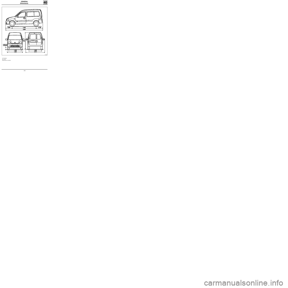
Dimensions
(1) Unladen
(2) Laden
Dimensions in metres.
40
12333R
40-1
Page 6 of 255
GENERAL
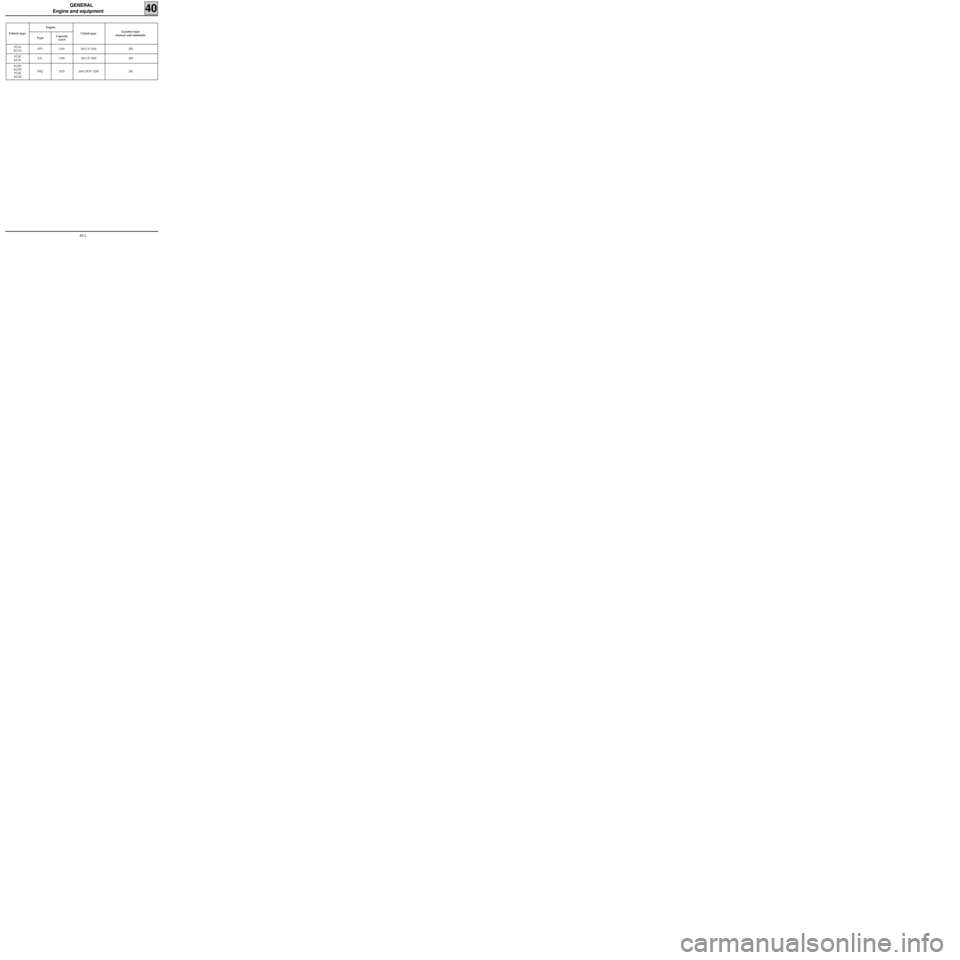
Engine and equipment
40
Vehicle type Engine
TypeCapacity
(cm
3)Clutch type Gearbox type
manual and automatic
FC0A
KC0AD7F 1149 180 CP 3300 JB1
FC0C
KC0CE7J 1390 180 CP 3300 JB3
FC0D
KC0D
FC0E
KC0EF8Q 1870 200 CPOV 3250 JB1
40-2
Page 7 of 255
GENERAL
Engine and equipment
40
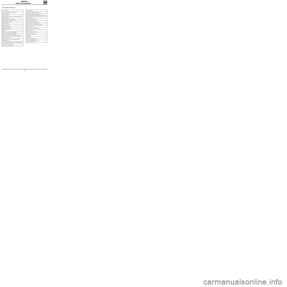
SPECIFIC BODYWORK FEATURES
Driver’s airbag
Passenger’s and driver’s airbag
Height adjustable front head restraint
Height adjustable and tiltable front head restraint
Rear parcel shelf
Luggage compartment net
Electric one touch windows
Heated electric rear view mirrors
Heated screen + timed windscreen wiper
Heated front seats
Front seat driver emergency exit
Rear bench seat 1/1
Rear bench seat 1/3 - 2/3
Cabin rack without stop
Headlining
Boot carpet
Parcel shelf luggage cover
Two front fog lights in bumper
(excluding F8 AC PAS)Pay load 600 kg
Pay load 625 to 710 kg depending on
engine/equipment
Pay load 800 kg
Glazed, sliding side door and rear opening doors
or glazed tailgate
Sliding side door (reflective glass)
Sliding side door (panel)
Rear door, panel
Rear door, glazed
Opening doors, panels
Opening doors, glazed
Tailgate
Opaque roof flap (excluding tailgate)
Glazed roof flap (excluding tailgate)
Fixed side window (meaning glazed side door)
Sliding side window
Fixed rear quarter panel (meaning the glazed
sliding side door )
Heat insulating windscreen (with air conditioning)
2 point rear centre seat belt
3 point rear centre seat belt
40-3
Page 8 of 255
GENERAL
Identification
40
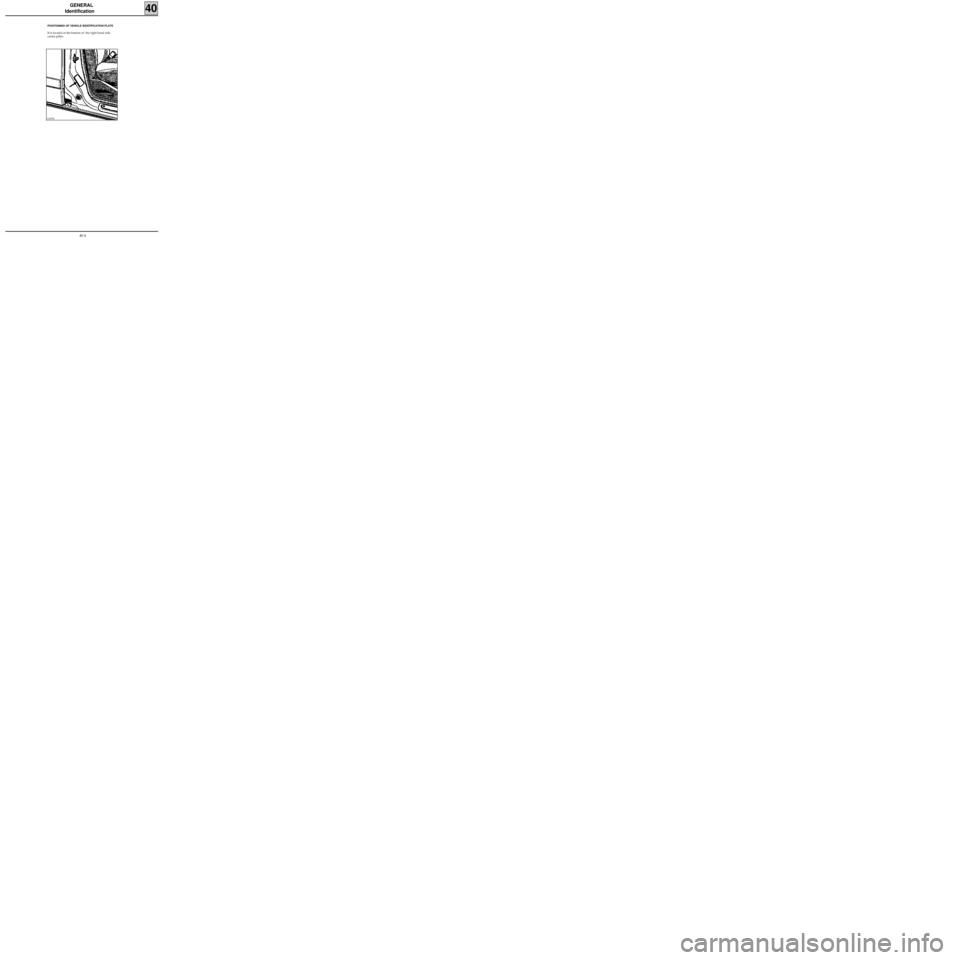
POSITIONING OF VEHICLE IDENTIFICATION PLATE
It is located at the bottom of the right hand side
centre pillar.
13187R
40-4
Page 9 of 255
GENERAL
Identification
40
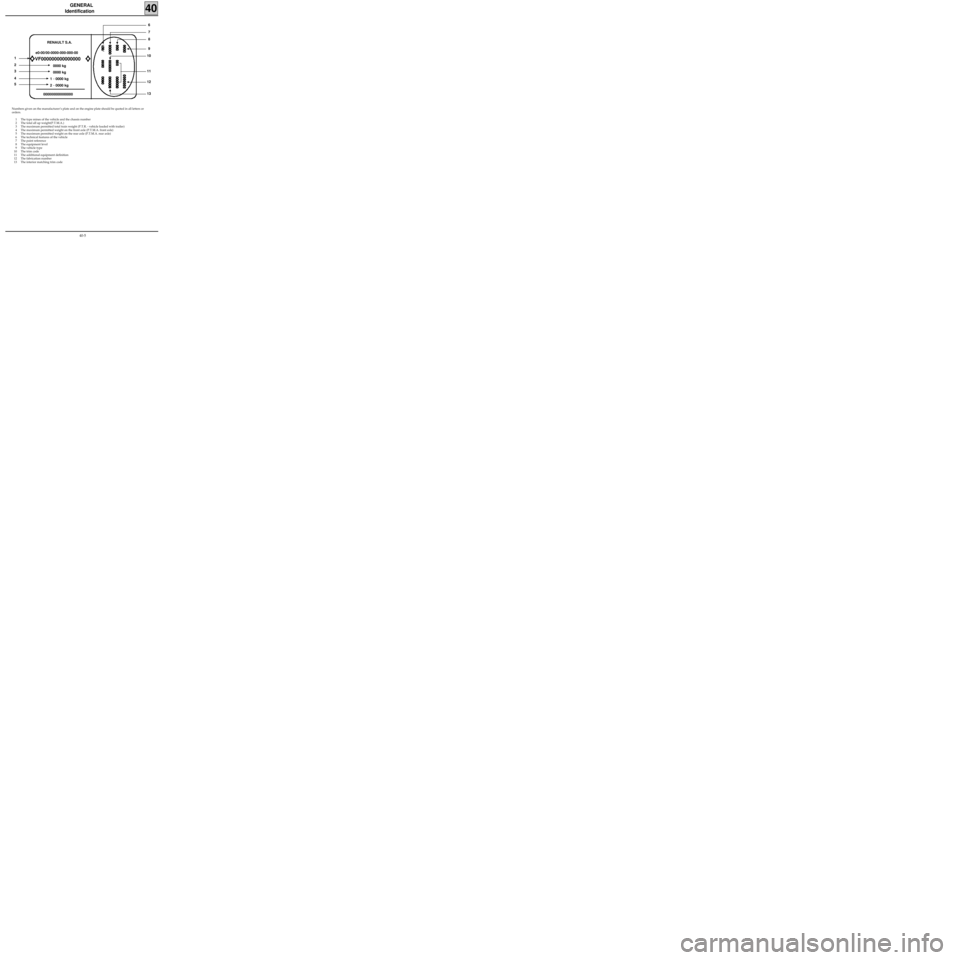
Numbers given on the manufacturer’s plate and on the engine plate should be quoted in all letters or
orders.
1 The type mines of the vehicle and the chassis number
2 The total all up weight(P.T.M.A.)
3 The maximum permitted total train weight (P.T.R. - vehicle loaded with trailer)
4 The maximum permitted weight on the front axle (P.T.M.A. front axle)
5 The maximum permitted weight on the rear axle (P.T.M.A. rear axle)
6 The technical features of the vehicle
7 The paint reference
8 The equipment level
9 The vehicle type
10 The trim code
11 The additional equipment definition
12 The fabrication number
13 The interior matching trim code
e0-00/00-0000-000-000-00
VF000000000000000
0000 kg
0000 kg
1
- 0000 kg
2
- 0000 kg
000000000000000RENAULT S.A.
1
2
3
4
5
8 7
6
9
10
13
12 11
40-5
Page 10 of 255
GENERAL
Means of lifting
40
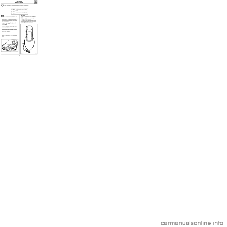
AXLE STANDS
To place the vehicle on axle stands, they MUSTbe
placed:
- either under the reinforcements provided for
lifting the vehicle with the jack which forms
part of the vehicle equipment,
- or under the points behind the reinforcements.
Rear positioning of the axle stands can be carried
out by lifting the vehicle from the side.
Safety symbol (special precautions to be taken when carrying out operations).
SPECIAL TOOLING REQUIRED
Cha. 280 -02 Adaptable cross piece for trolley
jack
Cha. 408 -01
or Adaptable socket for trolley jack
Cha. 408 -02
If a trolley jack is used, appropriate axle
stands must always be used.
The vehicle MUST NOT be lifted by supporting its
weight under the front suspension arms, or under
the V section rear axle.
According to the type of trolley jack, use sockets
Cha. 408-01 or Cha. 408-02 to position the cross
piece Cha. 280-02.
To lift at the front or rear, take the weight under
the vehicle jacking points.
LIFTING FROM THE SIDE WITH A TROLLEY JACK
Use cross piece Cha. 280-02.
Take the weight under the valance at the front
door.
Position the flange correctly in the cross member
groove.
12333-2G
12274-1R
85679-1G15
40-6