RENAULT KANGOO 1997 KC / 1.G Sheet Metal Work Owner's Guide
KANGOO 1997 KC / 1.G
RENAULT
RENAULT
https://www.carmanualsonline.info/img/7/1735/w960_1735-0.png
RENAULT KANGOO 1997 KC / 1.G Sheet Metal Work Owner's Guide
Trending: boot, ESP, wheel size, tow, lock, seats, clutch
Page 31 of 255
GENERAL
Repair Bench
40
12666R
Left hand side
I - PRINCIPLE REFERENCE POINTS FOR SETTING VEHICLE TRIM LEVEL
A - FRONT SUB-FRAME REAR MOUNTING
It is the principle front reference point.
Right hand side
12893R
1 - Front mechanical units removed
The bracket rests against the rear section of the
side member and is centred in the sub-frame
mounting hole.
NOTE :
- on the left hand side, the hole is round,
- on the right hand side it is a slot.
40-27
Page 32 of 255
GENERAL
Repair Bench
40
2 - Front mechanical units in place
The bracket covers the sub-frame mounting bolt
and rests against the mounting bolt washer.
NOTE : The two sides are not symmetrical, on the
right hand side the mounting is set on the rubber
mounting.
If the rear of the vehicle is being rebuilt, these
two points alone may be used to align and sup-
port the front of the vehicle.
I - PRINCIPLE REFERENCE POINTS FOR SETTING VEHICLE TRIM LEVEL (cont)
12845R
40-28
Page 33 of 255
GENERAL
Repair Bench
40
12844R1
Rear mechanical units in place or removed
The bracket rests under the side member and is
centred in the hole (square).
If the front section is being rebuilt, these two
points alone can be used to align and support the
rear of the vehicle.B - FRONT POINT OF REAR AXLE ASSEMBLY
It is the main rear reference point.
I - PRINCIPLE REFERENCE POINTS FOR SETTING VEHICLE TRIM LEVEL (cont)
12669R
Without mechanical units
With mechanical units
40-29
Page 34 of 255
GENERAL
Repair Bench
40
12666R1
This point is also used as a positioning reference
when replacing a rear section of the front side
member.
On the impact side, this point allows the vehicle
to be additionally supported with a reference
point on the opposite side.
NOTE : these points should only be used in the cir-
cumstances quoted, there is no need to use them
when the main reference points (points A and B)
are correct.
This additional reference function may also be fil-
led by the front side member ends check points
for a rear impact and vice versa.
II - ADDITIONAL REFERENCE POINTS FOR SETTING VEHICLE TRIM LEVEL
These are the provisional reference points which
replace the main ones, when they have been af-
fected by the impact.
G - FRONT SIDE MEMBER, REAR SECTION
40-30
Page 35 of 255
GENERAL
Repair Bench
40
12843R1
2 - Front mechanical units in place
The bracket covers the sub-frame mounting bolt
and washer.
It is used:
- following a frontal collision for a slight im-
pact,
- for fault finding for the gauge inspection of
the front section .
C - FRONT SUB-FRAME FRONT MOUNTINGIII - REFERENCE POINTS FOR POSITIONING REPLACED PARTS
12668R
1 - Front mechanical units removed
The bracket rests under the sub-frame front
mounting and is centred in the hole with the
mounting bolt.
It is used when replacing :
- a front end cross member,
- a side member, part section,
- a half unit.
40-31
Page 36 of 255
GENERAL
Repair Bench
40
12841S
The bracket rests under the shock absorber cup
and is centred in the shock absorber mounting
hole.
It is used when replacing :
- wheel arches,
- a front half unit.
It is also used when straightening. E -
REAR SHOCK ABSORBER UPPER MOUNTINGIII - REFERENCE POINTS FOR POSITIONING REPLACED PARTS (cont)
12665R
The bracket is fitted at the shock absorber clevis
location and positions this mounting for repla-
cing :
- a rear side member,
- the rear floor unit.
It is also used when straightening.F -
FRONT SHOCK ABSORBER UPPER
MOUNTING
40-32
Page 37 of 255
GENERAL
Repair Bench
40
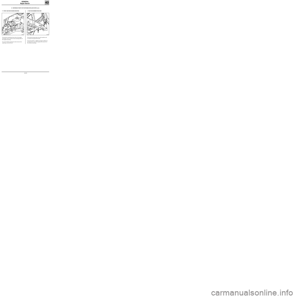
12667R
The bracket touches below the side member and
is centred in the pilot hole (slot).
It may be used for a slight rear impact without re-
moving the rear axle, but requires the removal of
the exhaust mounting.
P - FRONT AND REAR ENGINE MOUNTINGIII - REFERENCE POINTS FOR POSITIONING REPLACED PARTS (cont)
12841S
The bracket is positioned from above the engine
mounting, and is centred in the mounting holes of
the engine mounting.
It is used with the mechanical units removed for
replacing a front half unit.
J - REAR SIDE MEMBER REAR END
40-33
Page 38 of 255
GENERAL
Repair Bench
40
12668R1
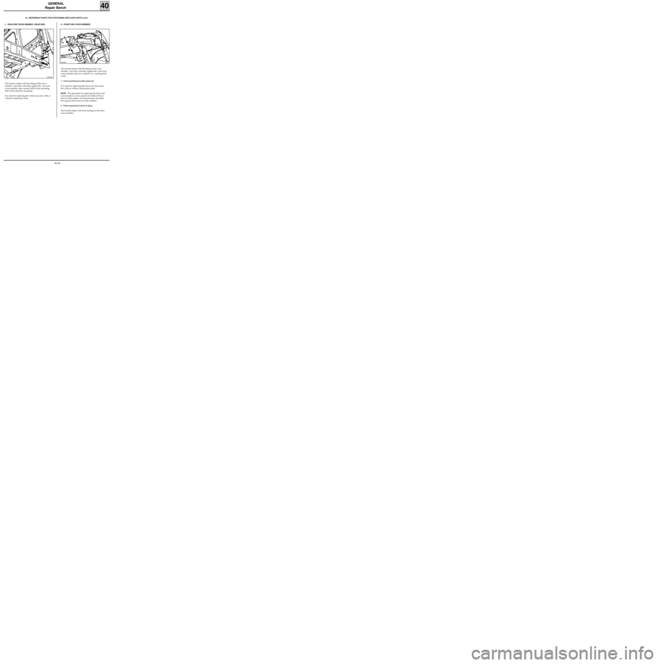
The bracket helps with the fitting of the cross
member and rests vertically against the front end
cross member, then it is centred by a centring bolt
at (K).
1 - Front mechanical units removed
It is used for replacing the front end cross mem-
ber, with or without mechanical units.
NOTE : The operation for replacing the front end
cross member can be carried out without the re-
moval of the engine and transmission assembly,
but requires the removal of the radiator.
2 - Front mechanical units in place
The bracket helps with fault finding on the front
cross member.
III - REFERENCE POINTS FOR POSITIONING REPLACED PARTS (cont)
L - REAR END CROSS MEMBER (REAR END)
12667R1
The bracket helps with the fitting of the cross
member and rests vertically against the rear end
cross member, then centres itself in the mounting
hole of the absorber mounting.
It is used for replacing the whole rear end, with or
without mechanical units.
K - FRONT END CROSS MEMBER
40-34
Page 39 of 255
GENERAL
Repair Bench
40
PRB4005
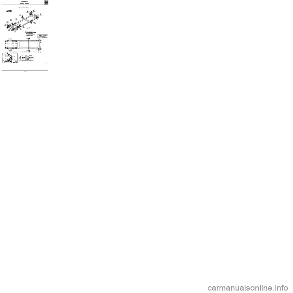
CELETTE REPAIR BENCH
40-35
Page 40 of 255
GENERAL
Repair Bench
40
PRB4006
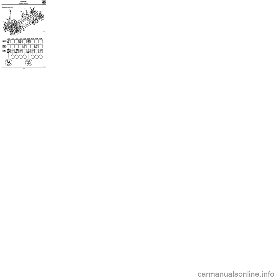
BLACKHAWK REPAIR BENCH
PRB4007
40-36
Trending: jack points, weight, suspension, window, mirror, gearbox, transmission
