SSANGYONG MUSSO 1998 Workshop Repair Manual
MUSSO 1998
SSANGYONG
SSANGYONG
https://www.carmanualsonline.info/img/67/57510/w960_57510-0.png
SSANGYONG MUSSO 1998 Workshop Repair Manual
Trending: height adjustment, boot, ground clearance, lug pattern, flat tire, coolant reservoir, lights
Page 381 of 1463
OM600 ENGINE MECHANICAL 1B3-79
5. Install the timing sensor bracket.
Notice
See the ‘TDC setting’.
6. Install the cooling fan pulley.
Tightening Torque 10 Nm
7. Install the cooling fan.
8. Install the fan belt.
9. Remove the engine lock.
Page 382 of 1463
1B3-80 OM600 ENGINE MECHANICAL
CRANKSHAFT FRONT RADIAL SEAL
1 Radial Seal
2 Timing Case Cover
Tools Required
601 589 03 14 00 Sleeve3 Woodruff Key
Page 383 of 1463
OM600 ENGINE MECHANICAL 1B3-81
Notice
The sealing lip of the repair radial seal is offset to the inside
by 2mm to ensure that is does not run in any groove which
the standard radial seal may have left on the crankshaft
flange.
A Standard Radial Seal
B Repair Radial Seal
Replacement Procedure
1. Pull out the radial seal (1) and be careful not to damage the
sealing surface of timing case cover.
2. Thoroughly clean the mounting bore of the radial seal.
3. Coat a little oil on the sealing lip of new radial (1) and contact
surface.
Notice
Don’t use grease.
4. Install the radial seal (1) by using a sleeve (4).
Notice
Align the groove of sleeve and woodruff key(arrow).
Sleeve 601 589 03 14
Page 384 of 1463
1B3-82 OM600 ENGINE MECHANICAL
CRANKSHAFT BALL BEARING
1 Spacer
2 Cover ......................................... Replace
Notice
Manual transmission only.
Tools Required
000 589 33 33 00 Counter Support
000 589 25 33 00 Internal Extractor
Removal & Installation Procedure
1. Remove the manual transmission.
2. Using a puller, pull out the locking ring and ball bearing
together.
Counter Support 000 589 33 33 00
Internal Extractor 000 589 25 33 00
3. Apply Loctite 241 on the new ball bearing and then insert
the ball bearing to be stopped at the spacer ring by using a
proper mandrel.
3 Ball Bearing
4 Bolt.......................................45Nm + 90°
Page 385 of 1463
OM600 ENGINE MECHANICAL 1B3-83
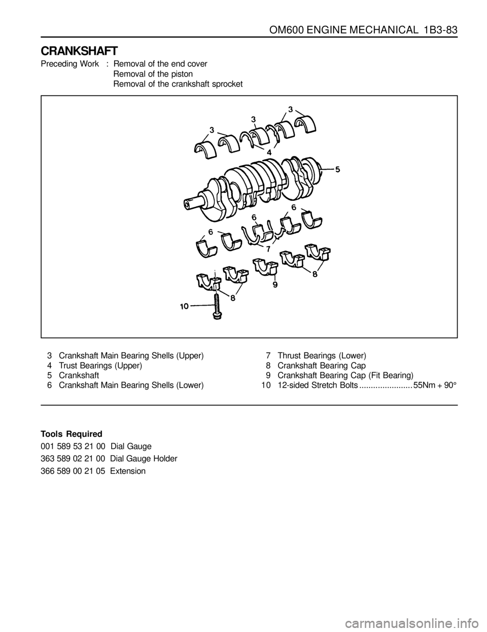
CRANKSHAFT
Preceding Work : Removal of the end cover
Removal of the piston
Removal of the crankshaft sprocket
3 Crankshaft Main Bearing Shells (Upper)
4 Trust Bearings (Upper)
5 Crankshaft
6 Crankshaft Main Bearing Shells (Lower)7 Thrust Bearings (Lower)
8 Crankshaft Bearing Cap
9 Crankshaft Bearing Cap (Fit Bearing)
10 12-sided Stretch Bolts.......................55Nm + 90°
Tools Required
001 589 53 21 00 Dial Gauge
363 589 02 21 00 Dial Gauge Holder
366 589 00 21 05 Extension
Page 386 of 1463
1B3-84 OM600 ENGINE MECHANICAL
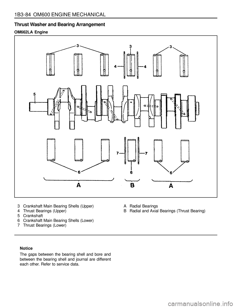
3 Crankshaft Main Bearing Shells (Upper)
4 Thrust Bearings (Upper)
5 Crankshaft
6 Crankshaft Main Bearing Shells (Lower)
7 Thrust Bearings (Lower)A Radial Bearings
B Radial and Axial Bearings (Thrust Bearing)
Notice
The gaps between the bearing shell and bore and
between the bearing shell and journal are different
each other. Refer to service data.
Thrust Washer and Bearing Arrangement
OM662LA Engine
Page 387 of 1463
OM600 ENGINE MECHANICAL 1B3-85
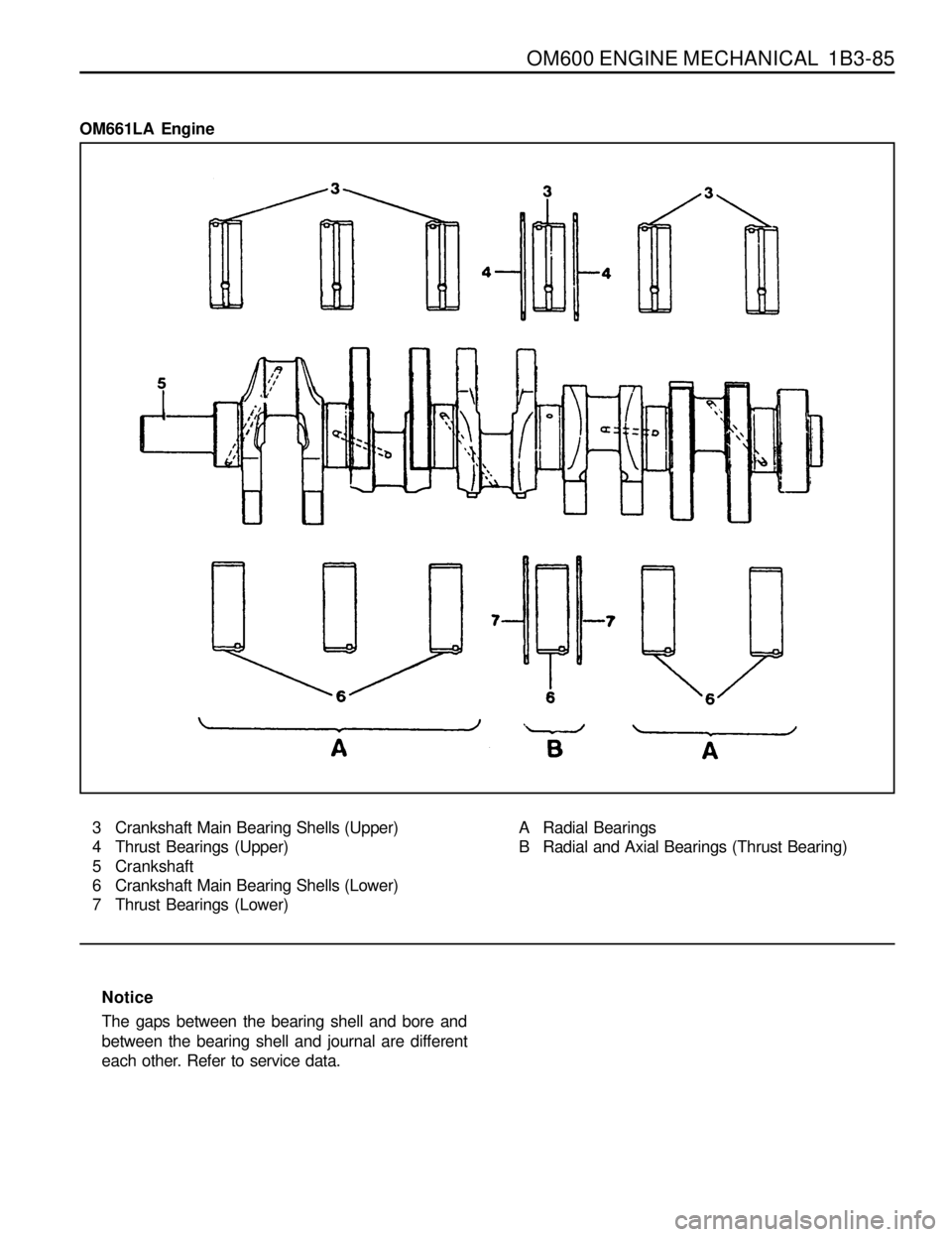
3 Crankshaft Main Bearing Shells (Upper)
4 Thrust Bearings (Upper)
5 Crankshaft
6 Crankshaft Main Bearing Shells (Lower)
7 Thrust Bearings (Lower)A Radial Bearings
B Radial and Axial Bearings (Thrust Bearing)
Notice
The gaps between the bearing shell and bore and
between the bearing shell and journal are different
each other. Refer to service data.
OM661LA Engine
Page 388 of 1463
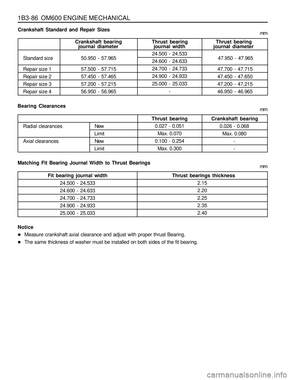
1B3-86 OM600 ENGINE MECHANICAL
24.500 - 24.533
24.600 - 24.633
24.700 - 24.733
24.900 - 24.933
25.000 - 25.033New
Limit
New
Limit Radial clearances
Axial clearancesCrankshaft bearing
journal diameter Crankshaft Standard and Repair Sizes
Standard size 50.950 - 57.965
journal width
24.500 - 24.533
24.600 - 24.633
24.700 - 24.733
24.900 - 24.933
25.000 - 25.033
-Thrust bearing
journal diameter
47.950 - 47.965 Thrust bearing
47.700 - 47.715
47.450 - 47.650
47.200 - 47.215
46.950 - 46.965 57.500 - 57.715
57.450 - 57.465
57.200 - 57.215
56.950 - 56.965 Repair size 1
Repair size 2
Repair size 3
Repair size 4
Bearing Clearances
Thrust bearingCrankshaft bearing
0.026 - 0.068
Max. 0.080
-
- 0.027 - 0.051
Max. 0.070
0.100 - 0.254
Max. 0.300
Matching Fit Bearing Journal Width to Thrust Bearings
Fit bearing journal width Thrust bearings thickness
2.15
2.20
2.25
2.35
2.40
Notice
lMeasure crankshaft axial clearance and adjust with proper thrust Bearing.
lThe same thickness of washer must be installed on both sides of the fit bearing.mm
mm
mm
Page 389 of 1463
OM600 ENGINE MECHANICAL 1B3-87
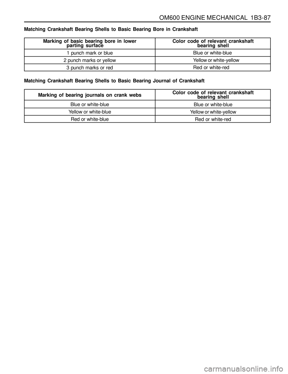
bearing shell Matching Crankshaft Bearing Shells to Basic Bearing Bore in Crankshaft
Matching Crankshaft Bearing Shells to Basic Bearing Journal of Crankshaft
Marking of basic bearing bore in lowerColor code of relevant crankshaft
parting surface
1 punch mark or blue
2 punch marks or yellow
3 punch marks or redbearing shell
Blue or white-blue
Yellow or white-yellow
Red or white-red
Marking of bearing journals on crank websColor code of relevant crankshaft
Blue or white-blue
Yellow or white-blue
Red or white-blueBlue or white-blue
Yellow or white-yellow
Red or white-red
Page 390 of 1463
1B3-88 OM600 ENGINE MECHANICAL
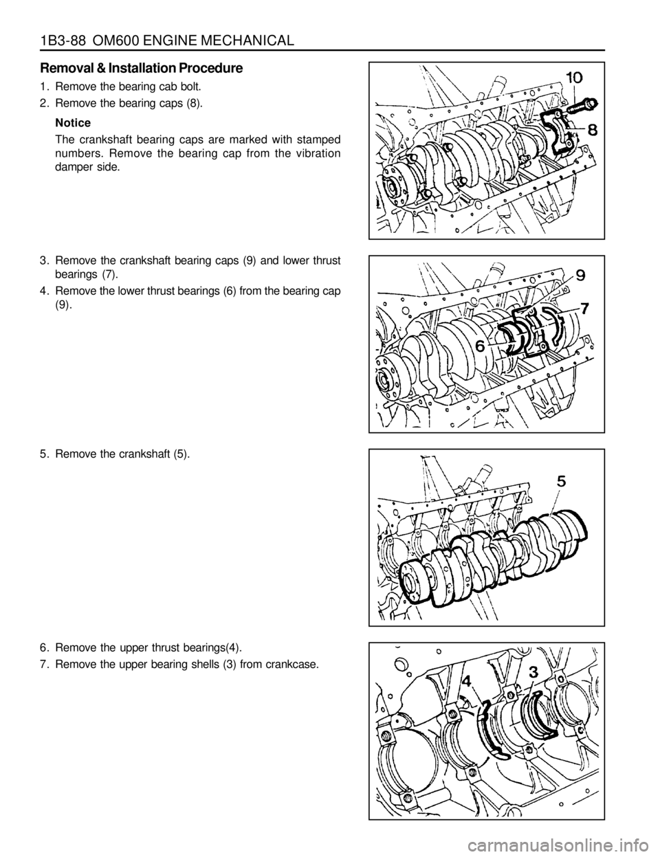
Removal & Installation Procedure
1. Remove the bearing cab bolt.
2. Remove the bearing caps (8).
Notice
The crankshaft bearing caps are marked with stamped
numbers. Remove the bearing cap from the vibration
damper side.
3. Remove the crankshaft bearing caps (9) and lower thrust
bearings (7).
4. Remove the lower thrust bearings (6) from the bearing cap
(9).
5. Remove the crankshaft (5).
6. Remove the upper thrust bearings(4).
7. Remove the upper bearing shells (3) from crankcase.
Trending: power steering, height, wheel bolt torque, headlamp, window, spark plugs replace, fuel tank removal


