TOYOTA RAV4 1996 Service Repair Manual
Manufacturer: TOYOTA, Model Year: 1996, Model line: RAV4, Model: TOYOTA RAV4 1996Pages: 1632, PDF Size: 41.64 MB
Page 901 of 1632
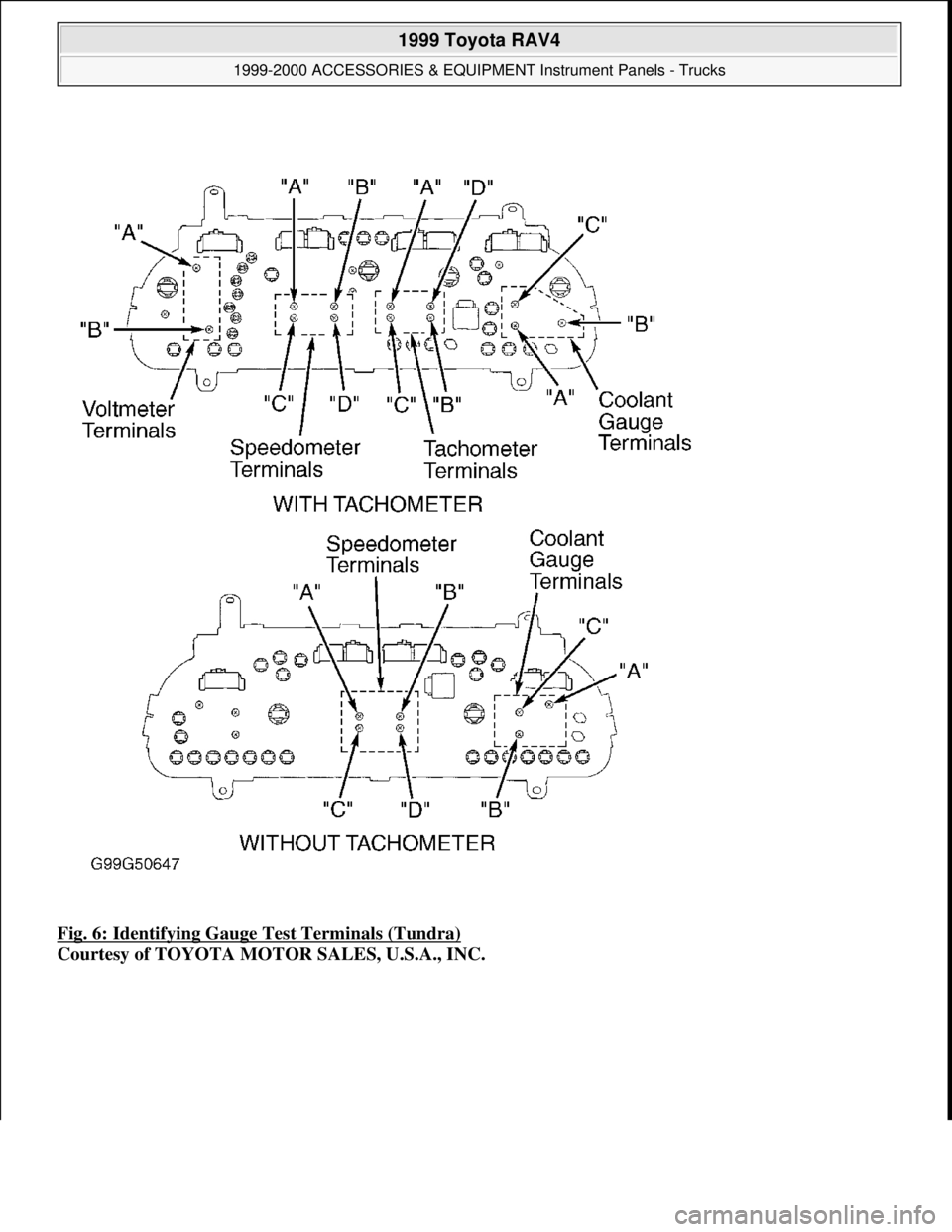
Fig. 6: Identifying Gauge Test Terminals (Tundra)
Courtesy of TOYOTA MOTOR SALES, U.S.A., INC.
1999 Toyota RAV4
1999-2000 ACCESSORIES & EQUIPMENT Instrument Panels - Trucks
Microsoft
Sunday, November 22, 2009 10:54:10 AMPage 11 © 2005 Mitchell Repair Information Company, LLC.
Page 902 of 1632
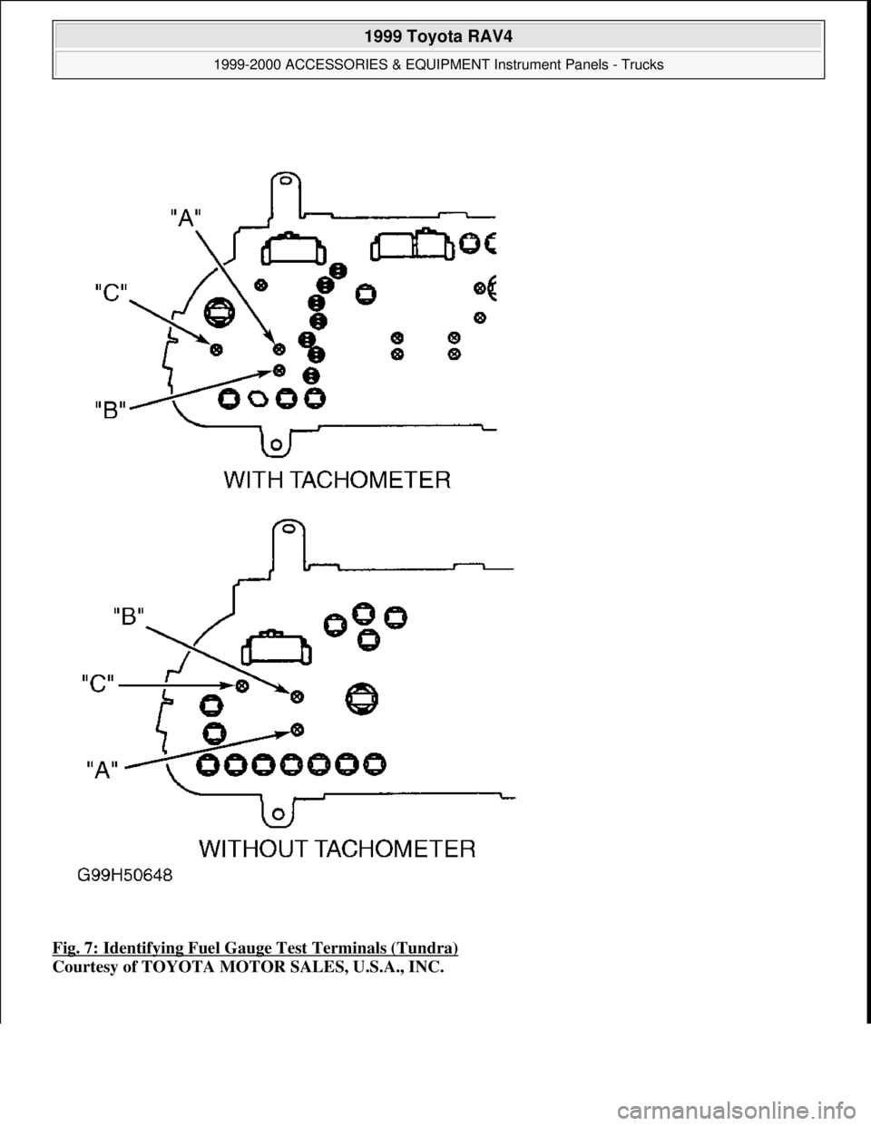
Fig. 7: Identifying Fuel Gauge Test Terminals (Tundra)
Courtesy of TOYOTA MOTOR SALES, U.S.A., INC.
1999 Toyota RAV4
1999-2000 ACCESSORIES & EQUIPMENT Instrument Panels - Trucks
Microsoft
Sunday, November 22, 2009 10:54:10 AMPage 12 © 2005 Mitchell Repair Information Company, LLC.
Page 903 of 1632
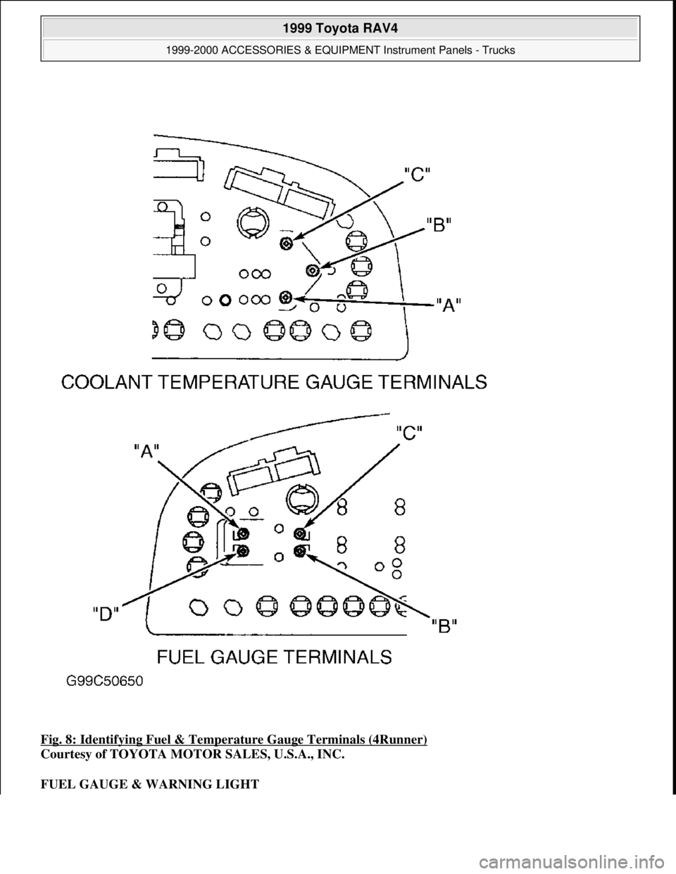
Fig. 8: Identifying Fuel & Temperature Gauge Terminals (4Runner)
Courtesy of TOYOTA MOTOR SALES, U.S.A., INC.
FUEL GAUGE & WARNING LIGHT
1999 Toyota RAV4
1999-2000 ACCESSORIES & EQUIPMENT Instrument Panels - Trucks
Microsoft
Sunday, November 22, 2009 10:54:10 AMPage 13 © 2005 Mitchell Repair Information Company, LLC.
Page 904 of 1632
Fuel Gauge & Wiring Harness Operational Test (Land Cruiser & Tundra)
Disconnect Dark Gray 5-pin fuel tank sending unit connector. Turn ignition switch to ON position. If fuel gauge
indicates EMPTY, check fuel gauge sending unit. See FUEL GAUGE SENDING UNIT TESTS
. If fuel
gauge does not indicate EMPTY, repair short in wiring harness. See WIRING DIAGRAMS
.
Fuel Gauge & Wiring Harness Operational Test (RAV4)
1. Disconnect Dark Gray 5-pin fuel tank main sending unit connector. Turn ignition switch to ON position.
If fuel gauge indicates EMPTY, go to next step. If fuel gauge does not indicate EMPTY, repair short in
wiring harness. See WIRING DIAGRAMS
.
2. Reconnect main sending unit connector. Disconnect Gray 2-pin fuel tank sub sending unit connector.
Turn ignition switch to ON position. If fuel gauge indicates EMPTY, go to next step. If fuel gauge does
not indicate EMPTY, repair short in wiring harness. See WIRING DIAGRAMS
.
3. Disconnect Dark Gray 5-pin fuel tank main sending unit connector. Connect a 12-volt, 3.4-watt test light
between terminal No. 3 of main sending unit wiring harness connector and terminal No. 1 of sub sending
unit wiring harness connector. See Fig. 9
and Fig. 10 .
4. With ignition switch in ON position, test light should be on and gauge needle should move toward FULL.
If test light is off and gauge needle does not move, check wiring harness for open. Repair as necessary. If
wiring harness checks good, perform FUEL GAUGE RESISTANCE TEST
.
Fuel Gauge & Wiring Harness Operational Test (Except Land Cruiser, RAV4 & Tundra)
1. Disconnect fuel tank sending unit connector. Turn ignition switch to ON position. If fuel gauge indicates
EMPTY, go to next step. If fuel gauge does not indicate EMPTY, repair short in wiring harness. See
WIRING DIAGRAMS
.
2. Connect a 12-volt, 3.4-watt test light between appropriate terminals of sending unit wiring harness
connector. See FUEL GAUGE & HARNESS TEST
table. See Fig. 9 and Fig. 10 .
3. With ignition switch in ON position, test light should be on and gauge needle should move toward FULL.
If test light is not on and gauge needle does not move, check wiring harness for open. Repair as
necessary. If wiring harness is okay, perform FUEL GAUGE RESISTANCE TEST
.
FUEL GAUGE & HARNESS TEST
ModelSending Unit Harness Connector Terminals No.
Sienna, Tacoma & 4Runner2 & 3
1999 Toyota RAV4
1999-2000 ACCESSORIES & EQUIPMENT Instrument Panels - Trucks
Microsoft
Sunday, November 22, 2009 10:54:10 AMPage 14 © 2005 Mitchell Repair Information Company, LLC.
Page 905 of 1632
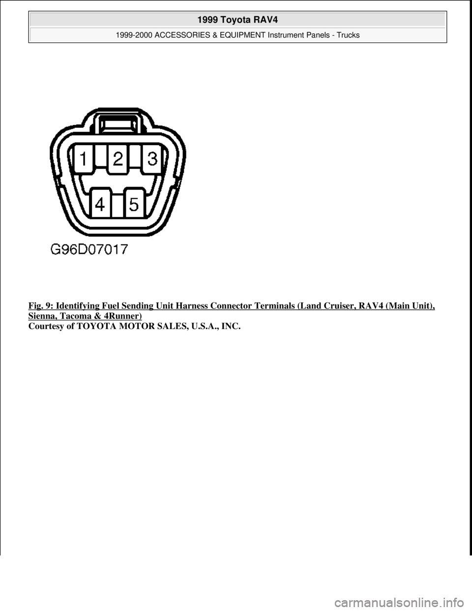
Fig. 9: Identifying Fuel Sending Unit Harness Connector Terminals (Land Cruiser, RAV4 (Main Unit),
Sienna, Tacoma & 4Runner)
Courtesy of TOYOTA MOTOR SALES, U.S.A., INC.
1999 Toyota RAV4
1999-2000 ACCESSORIES & EQUIPMENT Instrument Panels - Trucks
Microsoft
Sunday, November 22, 2009 10:54:10 AMPage 15 © 2005 Mitchell Repair Information Company, LLC.
Page 906 of 1632
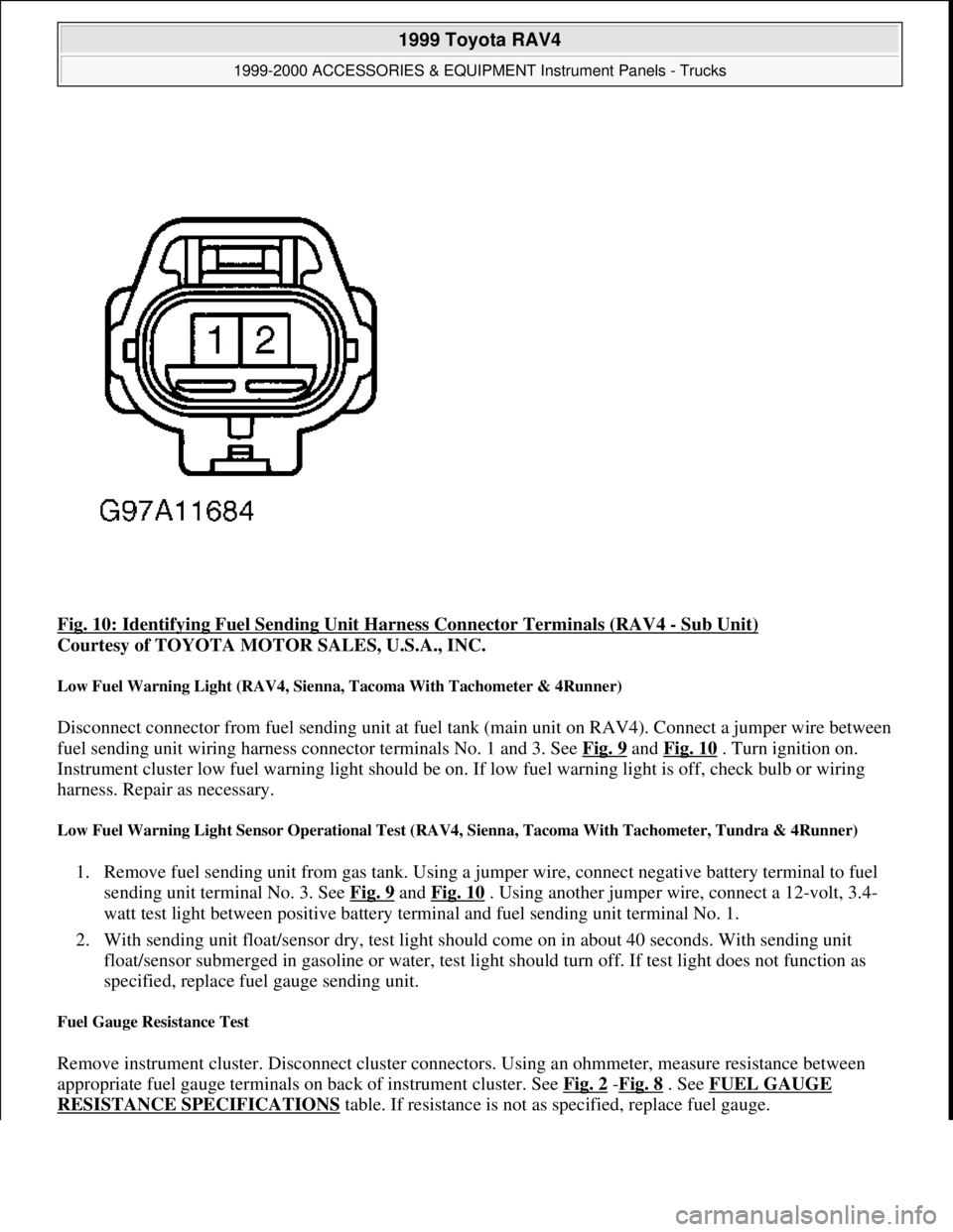
Fig. 10: Identifying Fuel Sending Unit Harness Connector Terminals (RAV4 - Sub Unit)
Courtesy of TOYOTA MOTOR SALES, U.S.A., INC.
Low Fuel Warning Light (RAV4, Sienna, Tacoma With Tachometer & 4Runner)
Disconnect connector from fuel sending unit at fuel tank (main unit on RAV4). Connect a jumper wire between
fuel sending unit wiring harness connector terminals No. 1 and 3. See Fig. 9
and Fig. 10 . Turn ignition on.
Instrument cluster low fuel warning light should be on. If low fuel warning light is off, check bulb or wiring
harness. Repair as necessary.
Low Fuel Warning Light Sensor Operational Test (RAV4, Sienna, Tacoma With Tachometer, Tundra & 4Runner)
1. Remove fuel sending unit from gas tank. Using a jumper wire, connect negative battery terminal to fuel
sending unit terminal No. 3. See Fig. 9
and Fig. 10 . Using another jumper wire, connect a 12-volt, 3.4-
watt test light between positive battery terminal and fuel sending unit terminal No. 1.
2. With sending unit float/sensor dry, test light should come on in about 40 seconds. With sending unit
float/sensor submerged in gasoline or water, test light should turn off. If test light does not function as
specified, replace fuel gauge sending unit.
Fuel Gauge Resistance Test
Remove instrument cluster. Disconnect cluster connectors. Using an ohmmeter, measure resistance between
appropriate fuel gauge terminals on back of instrument cluster. See Fig. 2
-Fig. 8 . See FUEL GAUGE
RESISTANCE SPECIFICATIONS table. If resistance is not as specified, replace fuel gauge.
1999 Toyota RAV4
1999-2000 ACCESSORIES & EQUIPMENT Instrument Panels - Trucks
Microsoft
Sunday, November 22, 2009 10:54:10 AMPage 16 © 2005 Mitchell Repair Information Company, LLC.
Page 907 of 1632
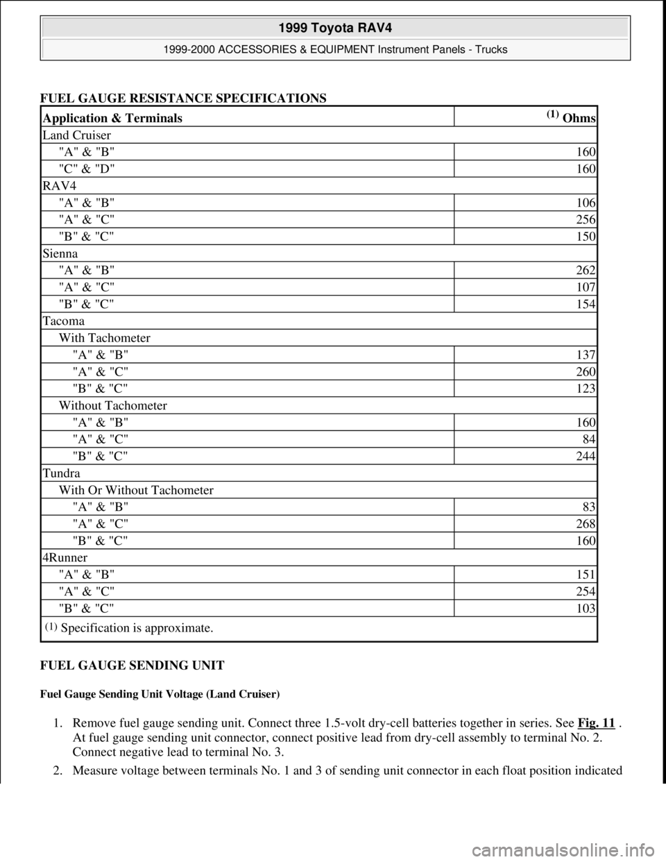
FUEL GAUGE RESISTANCE SPECIFICATIONS
FUEL GAUGE SENDING UNIT
Fuel Gauge Sending Unit Voltage (Land Cruiser)
1. Remove fuel gauge sending unit. Connect three 1.5-volt dry-cell batteries together in series. See Fig. 11 .
At fuel gauge sending unit connector, connect positive lead from dry-cell assembly to terminal No. 2.
Connect negative lead to terminal No. 3.
2. Measure volta
ge between terminals No. 1 and 3 of sending unit connector in each float position indicated
Application & Terminals(1) Ohms
Land Cruiser
"A" & "B"160
"C" & "D"160
RAV4
"A" & "B"106
"A" & "C"256
"B" & "C"150
Sienna
"A" & "B"262
"A" & "C"107
"B" & "C"154
Tacoma
With Tachometer
"A" & "B"137
"A" & "C"260
"B" & "C"123
Without Tachometer
"A" & "B"160
"A" & "C"84
"B" & "C"244
Tundra
With Or Without Tachometer
"A" & "B"83
"A" & "C"268
"B" & "C"160
4Runner
"A" & "B"151
"A" & "C"254
"B" & "C"103
(1)Specification is approximate.
1999 Toyota RAV4
1999-2000 ACCESSORIES & EQUIPMENT Instrument Panels - Trucks
Microsoft
Sunday, November 22, 2009 10:54:10 AMPage 17 © 2005 Mitchell Repair Information Company, LLC.
Page 908 of 1632
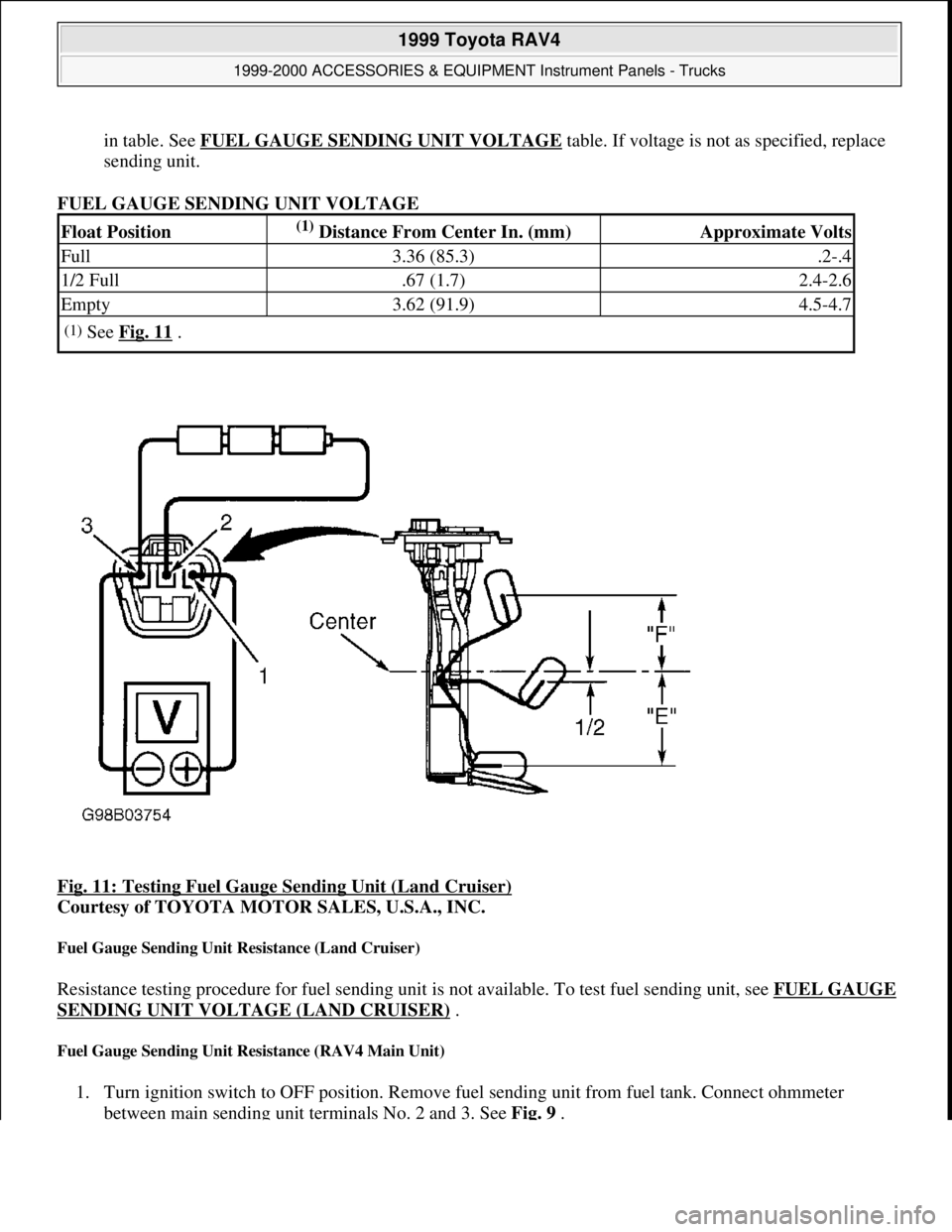
in table. See FUEL GAUGE SENDING UNIT VOLTAGEtable. If voltage is not as specified, replace
sending unit.
FUEL GAUGE SENDING UNIT VOLTAGE
Fig. 11: Testing Fuel Gauge Sending Unit (Land Cruiser)
Courtesy of TOYOTA MOTOR SALES, U.S.A., INC.
Fuel Gauge Sending Unit Resistance (Land Cruiser)
Resistance testing procedure for fuel sending unit is not available. To test fuel sending unit, see FUEL GAUGE
SENDING UNIT VOLTAGE (LAND CRUISER) .
Fuel Gauge Sending Unit Resistance (RAV4 Main Unit)
1. Turn ignition switch to OFF position. Remove fuel sending unit from fuel tank. Connect ohmmeter
between main sending unit terminals No. 2 and 3. See Fig. 9.
Float Position(1) Distance From Center In. (mm)Approximate Volts
Full3.36 (85.3).2-.4
1/2 Full.67 (1.7)2.4-2.6
Empty3.62 (91.9)4.5-4.7
(1)See Fig. 11 .
1999 Toyota RAV4
1999-2000 ACCESSORIES & EQUIPMENT Instrument Panels - Trucks
Microsoft
Sunday, November 22, 2009 10:54:10 AMPage 18 © 2005 Mitchell Repair Information Company, LLC.
Page 909 of 1632
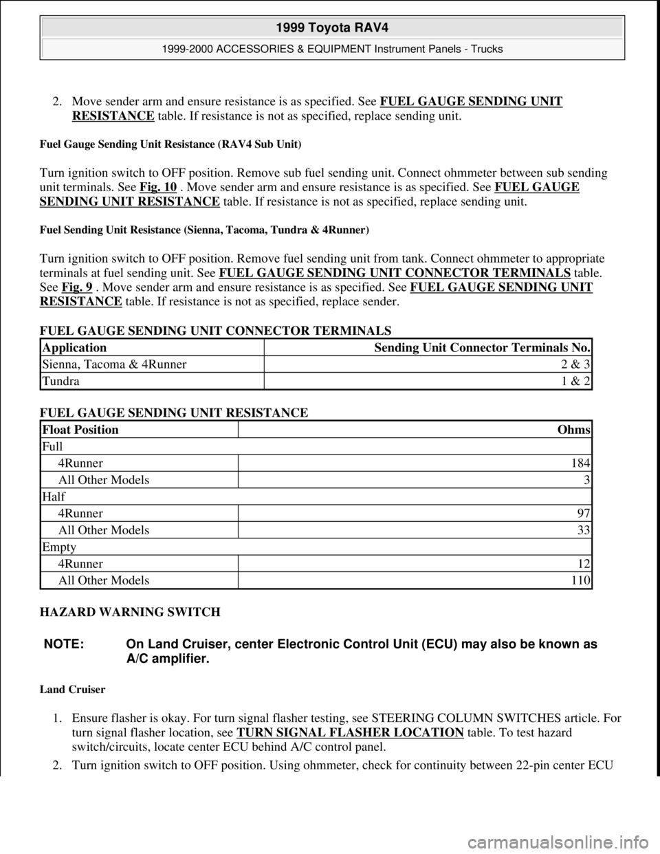
2. Move sender arm and ensure resistance is as specified. See FUEL GAUGE SENDING UNIT
RESISTANCE table. If resistance is not as specified, replace sending unit.
Fuel Gauge Sending Unit Resistance (RAV4 Sub Unit)
Turn ignition switch to OFF position. Remove sub fuel sending unit. Connect ohmmeter between sub sending
unit terminals. See Fig. 10
. Move sender arm and ensure resistance is as specified. See FUEL GAUGE
SENDING UNIT RESISTANCE table. If resistance is not as specified, replace sending unit.
Fuel Sending Unit Resistance (Sienna, Tacoma, Tundra & 4Runner)
Turn ignition switch to OFF position. Remove fuel sending unit from tank. Connect ohmmeter to appropriate
terminals at fuel sending unit. See FUEL GAUGE SENDING UNIT CONNECTOR TERMINALS
table.
See Fig. 9
. Move sender arm and ensure resistance is as specified. See FUEL GAUGE SENDING UNIT
RESISTANCE table. If resistance is not as specified, replace sender.
FUEL GAUGE SENDING UNIT CONNECTOR TERMINALS
FUEL GAUGE SENDING UNIT RESISTANCE
HAZARD WARNING SWITCH
Land Cruiser
1. Ensure flasher is okay. For turn signal flasher testing, see STEERING COLUMN SWITCHES article. For
turn signal flasher location, see TURN SIGNAL FLASHER LOCATION
table. To test hazard
switch/circuits, locate center ECU behind A/C control panel.
2. Turn ignition switch to OFF position. Using ohmmeter, check for continuity between 22-pin center ECU
ApplicationSending Unit Connector Terminals No.
Sienna, Tacoma & 4Runner2 & 3
Tundra1 & 2
Float PositionOhms
Full
4Runner184
All Other Models3
Half
4Runner97
All Other Models33
Empty
4Runner12
All Other Models110
NOTE: On Land Cruiser, center Electronic Control Unit (ECU) may also be known as
A/C amplifier.
1999 Toyota RAV4
1999-2000 ACCESSORIES & EQUIPMENT Instrument Panels - Trucks
Microsoft
Sunday, November 22, 2009 10:54:10 AMPage 19 © 2005 Mitchell Repair Information Company, LLC.
Page 910 of 1632
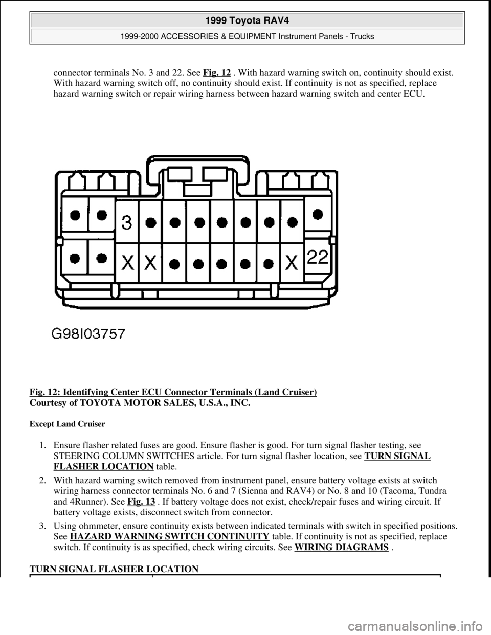
connector terminals No. 3 and 22. See Fig. 12. With hazard warning switch on, continuity should exist.
With hazard warning switch off, no continuity should exist. If continuity is not as specified, replace
hazard warning switch or repair wiring harness between hazard warning switch and center ECU.
Fig. 12: Identifying Center ECU Connector Terminals (Land Cruiser)
Courtesy of TOYOTA MOTOR SALES, U.S.A., INC.
Except Land Cruiser
1. Ensure flasher related fuses are good. Ensure flasher is good. For turn signal flasher testing, see
STEERING COLUMN SWITCHES article. For turn signal flasher location, see TURN SIGNAL
FLASHER LOCATION table.
2. With hazard warning switch removed from instrument panel, ensure battery voltage exists at switch
wiring harness connector terminals No. 6 and 7 (Sienna and RAV4) or No. 8 and 10 (Tacoma, Tundra
and 4Runner). See Fig. 13
. If battery voltage does not exist, check/repair fuses and wiring circuit. If
battery voltage exists, disconnect switch from connector.
3. Using ohmmeter, ensure continuity exists between indicated terminals with switch in specified positions.
See HAZARD WARNING SWITCH CONTINUITY
table. If continuity is not as specified, replace
switch. If continuity is as specified, check wiring circuits. See WIRING DIAGRAMS
.
TURN SIGNAL FLASHER LOCATION
1999 Toyota RAV4
1999-2000 ACCESSORIES & EQUIPMENT Instrument Panels - Trucks
Microsoft
Sunday, November 22, 2009 10:54:10 AMPage 20 © 2005 Mitchell Repair Information Company, LLC.