YAMAHA TTR90 2006 Betriebsanleitungen (in German)
Manufacturer: YAMAHA, Model Year: 2006, Model line: TTR90, Model: YAMAHA TTR90 2006Pages: 390, PDF-Größe: 9.12 MB
Page 121 of 390
2 - 22
SPEC
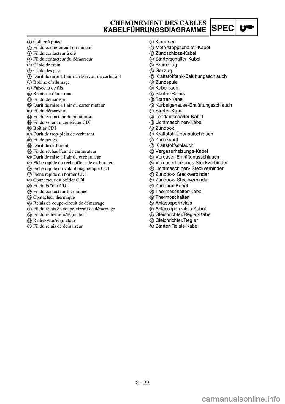
1Klammer
2Motorstoppschalter-Kabel
3Zündschloss-Kabel
4Starterschalter-Kabel
5Bremszug
6Gaszug
7Kraftstofftank-Belüftungsschlauch
8Zündspule
9Kabelbaum
0Starter-Relais
AStarter-Kabel
BKurbelgehäuse-Entlüftungsschlauch
CStarter-Kabel
DLeerlaufschalter-Kabel
ELichtmaschinen-Kabel
FZündbox
GKraftstoff-Überlaufschlauch
HZündkabel
IKraftstoffschlauch
JVergaserheizungs-Kabel
KVergaser-Entlüftungsschlauch
LVergaserheizungs-Steckverbinder
MLichtmaschinen- Steckverbinder
NZündbox- Steckverbinder
OZündbox- Steckverbinder
PZündbox-Kabel
QThermoschalter-Kabel
RThermoschalter
SAnlasssperrrelais
TAnlasssperrrelais-Kabel
UGleichrichter/Regler-Kabel
VGleichrichter/Regler
WStarter-Relais-Kabel
CHEMINEMENT DES CABLES
KABELFÜHRUNGSDIAGRAMME
1Collier à pince
2Fil du coupe-circuit du moteur
3Fil du contacteur à clé
4Fil du contacteur du démarreur
5Câble de frein
6Câble des gaz
7Durit de mise à l’air du réservoir de carburant
8Bobine d’allumage
9Faisceau de fils
0Relais de démarreur
AFil du démarreur
BDurit de mise à l’air du carter moteur
CFil du démarreur
DFil du contacteur de point mort
EFil du volant magnétique CDI
FBoîtier CDI
GDurit de trop-plein de carburant
HFil de bougie
IDurit de carburant
JFil du réchauffeur de carburateur
KDurit de mise à l’air du carburateur
LFiche rapide du réchauffeur de carburateur
MFiche rapide du volant magnétique CDI
NFiche rapide du boîtier CDI
OConnecteur du boîtier CDI
PFil du boîtier CDI
QFil du contacteur thermique
RContacteur thermique
SRelais de coupe-circuit de démarrage
TFil du relais de coupe-circuit de démarrage
UFil du redresseur/régulateur
VRedresseur/régulateur
WFil du relais de démarreur
Page 122 of 390
2 - 23
SPECCABLE ROUTING DIAGRAM
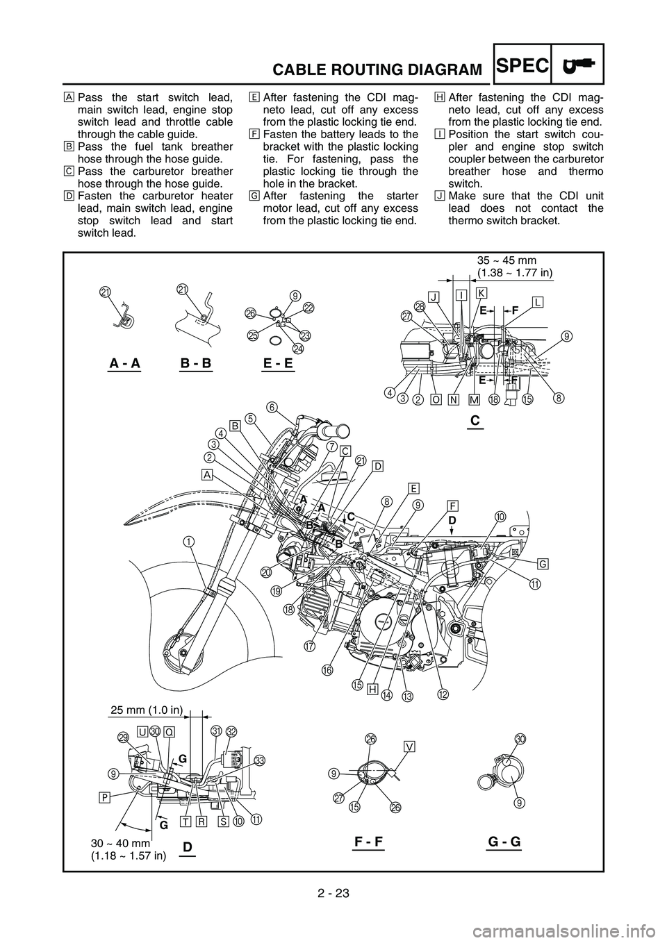
ÈPass the start switch lead,
main switch lead, engine stop
switch lead and throttle cable
through the cable guide.
ÉPass the fuel tank breather
hose through the hose guide.
ÊPass the carburetor breather
hose through the hose guide.
ËFasten the carburetor heater
lead, main switch lead, engine
stop switch lead and start
switch lead.ÌAfter fastening the CDI mag-
neto lead, cut off any excess
from the plastic locking tie end.
ÍFasten the battery leads to the
bracket with the plastic locking
tie. For fastening, pass the
plastic locking tie through the
hole in the bracket.
ÎAfter fastening the starter
motor lead, cut off any excess
from the plastic locking tie end.ÏAfter fastening the CDI mag-
neto lead, cut off any excess
from the plastic locking tie end.
ÐPosition the start switch cou-
pler and engine stop switch
coupler between the carburetor
breather hose and thermo
switch.
ÑMake sure that the CDI unit
lead does not contact the
thermo switch bracket.
A AA
C C
D
B
B B
BF FF
EE
D
A - AB - BE - E
C
F - FG - GD
KK
QRÑ
8
E
H
Ô 2 3 4
6
5
4
3
2
1
J
I
H
G
F
E
D
CBA 0 Í 9 8 Ë K 7
S
W U
V
A
0
Ú T
99
QP
PT
9 Ò
Ó
Õ Ö
Ê É
È
Ï
Ø
Ù
E
GGA
P
O
NML 9
Ð
9
Î
Û
Ý
25 mm (1.0 in)
×
Ì
35 ~ 45 mm
(1.38 ~ 1.77 in)
30 ~ 40 mm
(1.18 ~ 1.57 in)
Ü
Page 123 of 390
2 - 23
SPEC
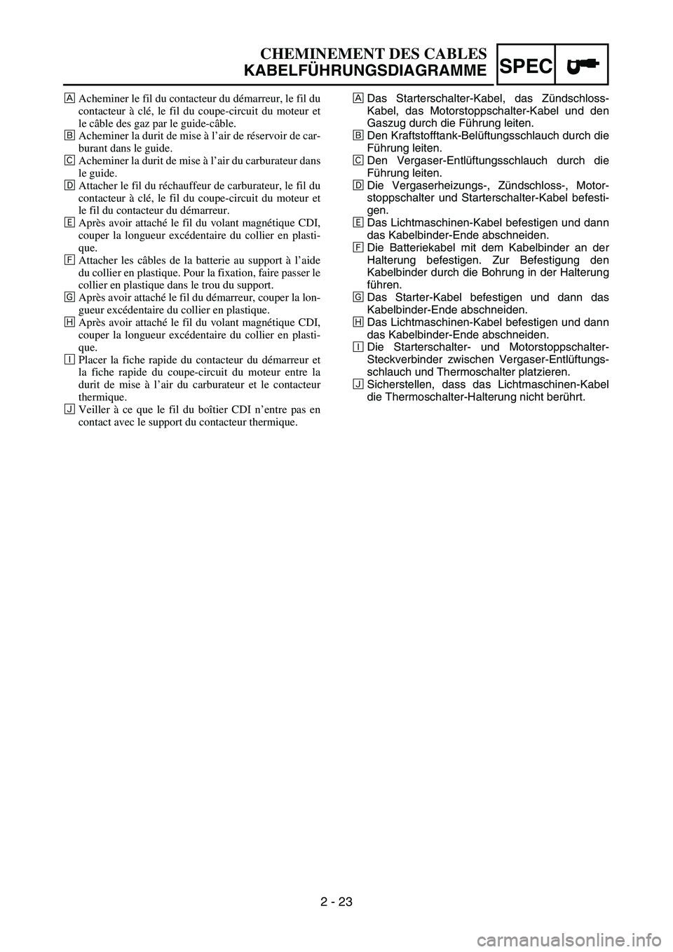
ÈDas Starterschalter-Kabel, das Zündschloss-
Kabel, das Motorstoppschalter-Kabel und den
Gaszug durch die Führung leiten.
ÉDen Kraftstofftank-Belüftungsschlauch durch die
Führung leiten.
ÊDen Vergaser-Entlüftungsschlauch durch die
Führung leiten.
ËDie Vergaserheizungs-, Zündschloss-, Motor-
stoppschalter und Starterschalter-Kabel befesti-
gen.
ÌDas Lichtmaschinen-Kabel befestigen und dann
das Kabelbinder-Ende abschneiden.
ÍDie Batteriekabel mit dem Kabelbinder an der
Halterung befestigen. Zur Befestigung den
Kabelbinder durch die Bohrung in der Halterung
führen.
ÎDas Starter-Kabel befestigen und dann das
Kabelbinder-Ende abschneiden.
ÏDas Lichtmaschinen-Kabel befestigen und dann
das Kabelbinder-Ende abschneiden.
ÐDie Starterschalter- und Motorstoppschalter-
Steckverbinder zwischen Vergaser-Entlüftungs-
schlauch und Thermoschalter platzieren.
ÑSicherstellen, dass das Lichtmaschinen-Kabel
die Thermoschalter-Halterung nicht berührt.
CHEMINEMENT DES CABLES
KABELFÜHRUNGSDIAGRAMME
ÈAcheminer le fil du contacteur du démarreur, le fil du
contacteur à clé, le fil du coupe-circuit du moteur et
le câble des gaz par le guide-câble.
ÉAcheminer la durit de mise à l’air de réservoir de car-
burant dans le guide.
ÊAcheminer la durit de mise à l’air du carburateur dans
le guide.
ËAttacher le fil du réchauffeur de carburateur, le fil du
contacteur à clé, le fil du coupe-circuit du moteur et
le fil du contacteur du démarreur.
ÌAprès avoir attaché le fil du volant magnétique CDI,
couper la longueur excédentaire du collier en plasti-
que.
ÍAttacher les câbles de la batterie au support à l’aide
du collier en plastique. Pour la fixation, faire passer le
collier en plastique dans le trou du support.
ÎAprès avoir attaché le fil du démarreur, couper la lon-
gueur excédentaire du collier en plastique.
ÏAprès avoir attaché le fil du volant magnétique CDI,
couper la longueur excédentaire du collier en plasti-
que.
ÐPlacer la fiche rapide du contacteur du démarreur et
la fiche rapide du coupe-circuit du moteur entre la
durit de mise à l’air du carburateur et le contacteur
thermique.
ÑVeiller à ce que le fil du boîtier CDI n’entre pas en
contact avec le support du contacteur thermique.
Page 124 of 390

2 - 24
SPECCABLE ROUTING DIAGRAM
ÒFasten the starter cable,
thermo switch lead, CDI unit
lead, main switch lead, start
switch lead and engine stop
switch lead.
ÓFasten the wire harness, CDI
unit leads, thermo switch lead
and CDI magneto lead.
ÔPass the carburetor heater
lead between the carburetor
breather hose and air intake
duct.ÕPosition the main switch cou-
pler between the carburetor
breather hose and air intake
duct.
ÖFasten the start switch lead,
main switch lead and engine
stop switch lead at the tape
with the plastic locking tie.
×Fasten the battery leads.ØFasten the wire harness and
starting circuit cut-off relay lead
at the tape for the wire harness
with the plastic locking tie.
ÙFasten the rectifier/regulator
lead and starter relay leads.
For fastening, pass the plastic
locking tie through the hole in
the battery box.
A AA
C C
D
B
B B
BF FF
EE
D
A - AB - BE - E
C
F - FG - GD
KK
QRÑ
8
E
H
Ô 2 3 4
6
5
4
3
2
1
J
I
H
G
F
E
D
CBA 0 Í 9 8 Ë K 7
S
W U
V
A
0
Ú T
99
QP
PT
9 Ò
Ó
Õ Ö
Ê É
È
Ï
Ø
Ù
E
GGA
P
O
NML 9
Ð
9
Î
Û
Ý
25 mm (1.0 in)
×
Ì
35 ~ 45 mm
(1.38 ~ 1.77 in)
30 ~ 40 mm
(1.18 ~ 1.57 in)
Ü
Page 125 of 390
2 - 24
SPEC
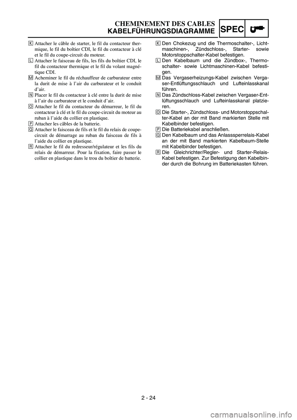
ÒDen Chokezug und die Thermoschalter-, Licht-
maschinen-, Zündschloss-, Starter- sowie
Motorstoppschalter-Kabel befestigen.
ÓDen Kabelbaum und die Zündbox-, Thermo-
schalter- sowie Lichtmaschinen-Kabel befesti-
gen.
ÔDas Vergaserheizungs-Kabel zwischen Verga-
ser-Entlüftungsschlauch und Lufteinlasskanal
führen.
ÕDas Zündschloss-Kabel zwischen Vergaser-Ent-
lüftungsschlauch und Lufteinlasskanal platzie-
ren.
ÖDie Starter-, Zündschloss- und Motorstoppschal-
ter-Kabel an der mit Band markierten Stelle mit
Kabelbinder befestigen.
×Die Batteriekabel anschließen.
ØDen Kabelbaum und das Anlasssperrelais-Kabel
an der mit Band markierten Kabelbaum-Stelle
mit Kabelbinder befestigen.
ÙDie Gleichrichter/Regler- und Starter-Relais-
Kabel befestigen. Zur Befestigung den Kabelbin-
der durch die Bohrung im Batteriekasten führen.
CHEMINEMENT DES CABLES
KABELFÜHRUNGSDIAGRAMME
ÒAttacher le câble de starter, le fil du contacteur ther-
mique, le fil du boîtier CDI, le fil du contacteur à clé
et le fil du coupe-circuit du moteur.
ÓAttacher le faisceau de fils, les fils du boîtier CDI, le
fil du contacteur thermique et le fil du volant magné-
tique CDI.
ÔAcheminer le fil du réchauffeur de carburateur entre
la durit de mise à l’air du carburateur et le conduit
d’air.
ÕPlacer le fil du contacteur à clé entre la durit de mise
à l’air du carburateur et le conduit d’air.
ÖAttacher le fil du contacteur du démarreur, le fil du
contacteur à clé et le fil du coupe-circuit du moteur au
ruban à l’aide du collier en plastique.
×Attacher les câbles de la batterie.
ØAttacher le faisceau de fils et le fil du relais de coupe-
circuit de démarrage au ruban du faisceau de fils à
l’aide du collier en plastique.
ÙAttacher le fil du redresseur/régulateur et les fils du
relais de démarreur. Pour la fixation, faire passer le
collier en plastique dans le trou du boîtier de batterie.
Page 126 of 390

2 - 25
SPECCABLE ROUTING DIAGRAM
ÚPass the starter relay lead
inside the starter relay.
ÛPut the white tape ends within
the area as shown by the
arrow.
ÜMake sure that the starting cir-
cuit cut-off relay lead does not
contact the spring (rear shock
absorber).ÝPosition the wire harness, CDI
magneto lead, thermo switch
lead and CDI unit lead as
shown.
A AA
C C
D
B
B B
BF FF
EE
D
A - AB - BE - E
C
F - FG - GD
KK
QRÑ
8
E
H
Ô 2 3 4
6
5
4
3
2
1
J
I
H
G
F
E
D
CBA 0 Í 9 8 Ë K 7
S
W U
V
A
0
Ú T
99
QP
PT
9 Ò
Ó
Õ Ö
Ê É
È
Ï
Ø
Ù
E
GGA
P
O
NML 9
Ð
9
Î
Û
Ý
25 mm (1.0 in)
×
Ì
35 ~ 45 mm
(1.38 ~ 1.77 in)
30 ~ 40 mm
(1.18 ~ 1.57 in)
Ü
Page 127 of 390
2 - 25
SPEC
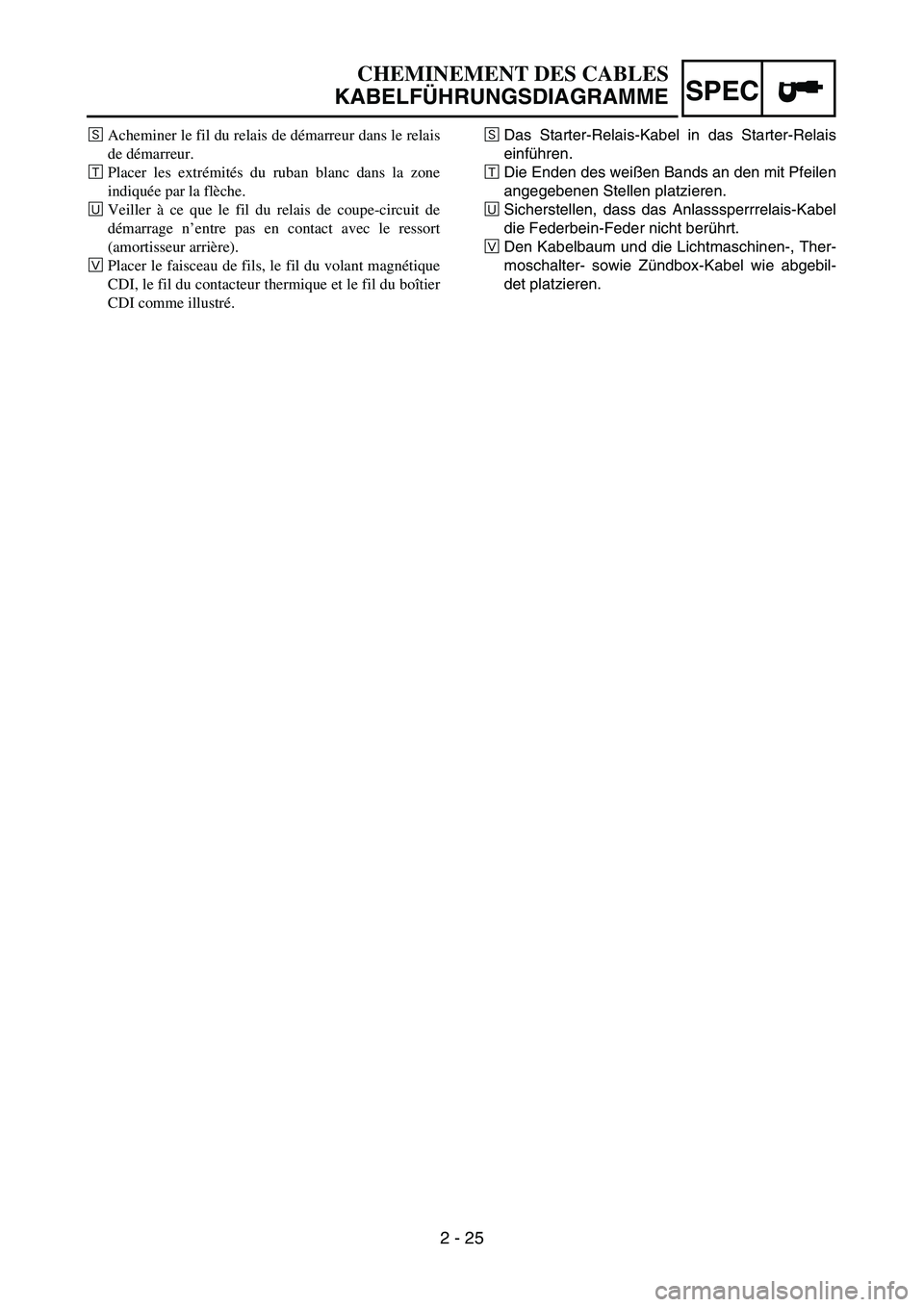
ÚDas Starter-Relais-Kabel in das Starter-Relais
einführen.
ÛDie Enden des weißen Bands an den mit Pfeilen
angegebenen Stellen platzieren.
ÜSicherstellen, dass das Anlasssperrrelais-Kabel
die Federbein-Feder nicht berührt.
ÝDen Kabelbaum und die Lichtmaschinen-, Ther-
moschalter- sowie Zündbox-Kabel wie abgebil-
det platzieren.
CHEMINEMENT DES CABLES
KABELFÜHRUNGSDIAGRAMME
ÚAcheminer le fil du relais de démarreur dans le relais
de démarreur.
ÛPlacer les extrémités du ruban blanc dans la zone
indiquée par la flèche.
ÜVeiller à ce que le fil du relais de coupe-circuit de
démarrage n’entre pas en contact avec le ressort
(amortisseur arrière).
ÝPlacer le faisceau de fils, le fil du volant magnétique
CDI, le fil du contacteur thermique et le fil du boîtier
CDI comme illustré.
Page 128 of 390
3 - 1
INSP
ADJ
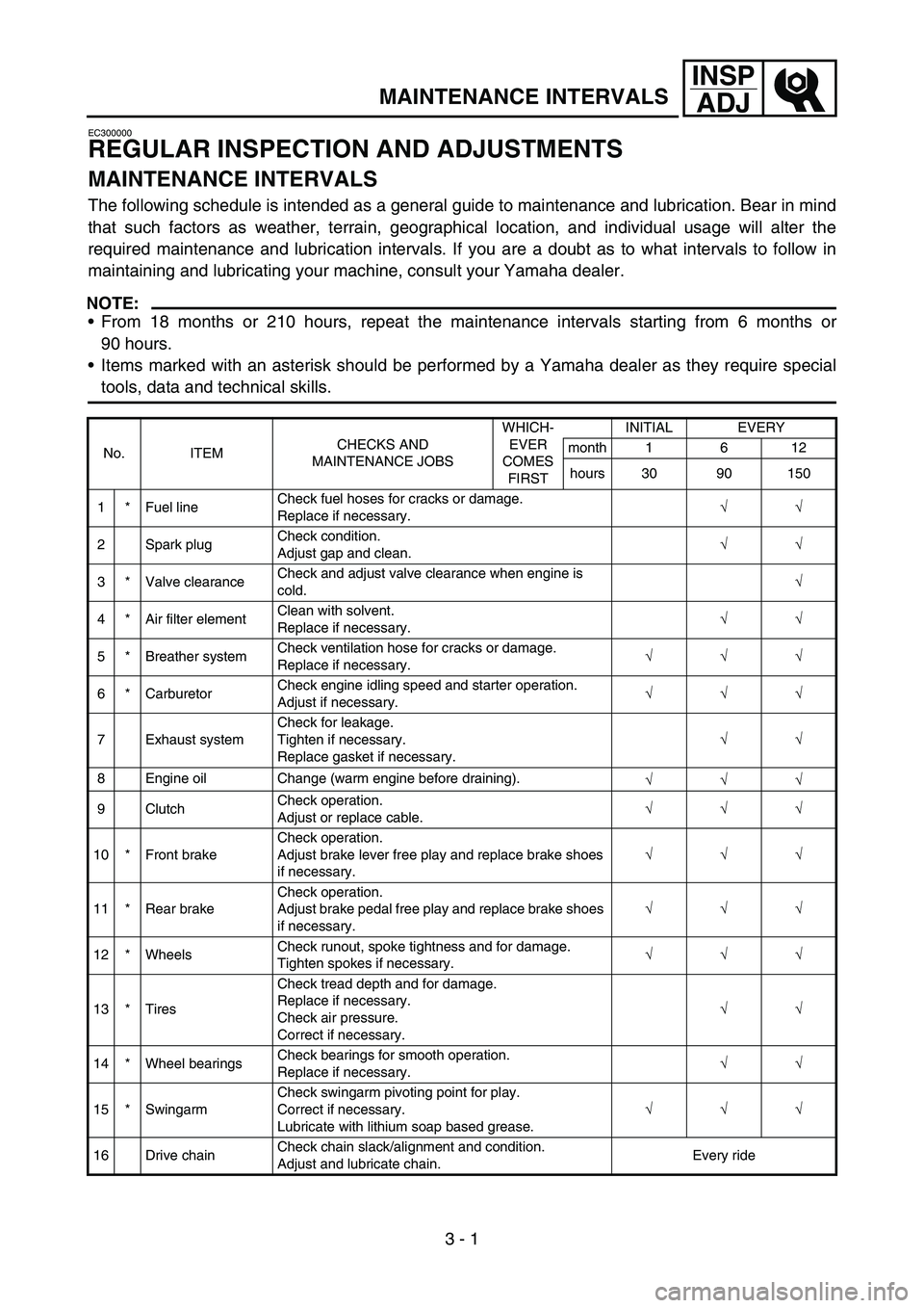
MAINTENANCE INTERVALS
EC300000
REGULAR INSPECTION AND ADJUSTMENTS
MAINTENANCE INTERVALS
The following schedule is intended as a general guide to maintenance and lubrication. Bear in mind
that such factors as weather, terrain, geographical location, and individual usage will alter the
required maintenance and lubrication intervals. If you are a doubt as to what intervals to follow in
maintaining and lubricating your machine, consult your Yamaha dealer.
NOTE:
From 18 months or 210 hours, repeat the maintenance intervals starting from 6 months or
90 hours.
Items marked with an asterisk should be performed by a Yamaha dealer as they require special
tools, data and technical skills.
No. ITEMCHECKS AND
MAINTENANCE JOBSWHICH-
EVER
COMES
FIRSTINITIAL EVERY
month 1 6 12
hours 30 90 150
1 * Fuel lineCheck fuel hoses for cracks or damage.
Replace if necessary.√
√
2 Spark plugCheck condition.
Adjust gap and clean.√
√
3 * Valve clearanceCheck and adjust valve clearance when engine is
cold.√
4 * Air filter elementClean with solvent.
Replace if necessary.√
√
5 * Breather systemCheck ventilation hose for cracks or damage.
Replace if necessary.√
√
√
6 * CarburetorCheck engine idling speed and starter operation.
Adjust if necessary.√
√
√
7 Exhaust systemCheck for leakage.
Tighten if necessary.
Replace gasket if necessary.√
√
8 Engine oil Change (warm engine before draining).
√
√
√
9 ClutchCheck operation.
Adjust or replace cable.√
√
√
10 * Front brakeCheck operation.
Adjust brake lever free play and replace brake shoes
if necessary.√
√
√
11 * Rear brakeCheck operation.
Adjust brake pedal free play and replace brake shoes
if necessary.√
√
√
12 * WheelsCheck runout, spoke tightness and for damage.
Tighten spokes if necessary.√
√
√
13 * TiresCheck tread depth and for damage.
Replace if necessary.
Check air pressure.
Correct if necessary.√
√
14 * Wheel bearingsCheck bearings for smooth operation.
Replace if necessary.√
√
15 * SwingarmCheck swingarm pivoting point for play.
Correct if necessary.
Lubricate with lithium soap based grease.√
√
√
16 Drive chainCheck chain slack/alignment and condition.
Adjust and lubricate chain.Every ride
3
Page 129 of 390

3 - 2
INSP
ADJ
MAINTENANCE INTERVALS
NOTE:
The air filter needs more frequent service if you are riding in unusually wet or dusty areas.
17 * Steering bearingsCheck bearing assemblies for looseness.
Lubricate with lithium soap based grease every or
120 hours or 12 months (whichever comes first).√
√
18Brake and clutch
lever pivot shaftsApply lithium soap based grease lightly.
√
√
√
19Brake pedal pivot
shaftApply lithium soap based grease lightly.
√
√
√
20 Sidestand pivotCheck operation.
Apply lithium soap based grease lightly.√
√
21 * Front forkCheck operation and for oil leakage.
Replace if necessary.√
√
22 *Shock absorber
assemblyCheck operation and for oil leakage.
Replace if necessary.√
√
23 * Control cablesApply Yamaha chain and cable lube or engine oil
10W-30 thoroughly.√
√
√
24 *Throttle grip hous-
ing and cableCheck operation and free play.
Adjust the throttle cable free play if necessary.
Lubricate the throttle grip housing and cable.√
√
√
25 * Chassis fastenersCheck all chassis fitting and fasteners.
Correct if necessary.√
√
√
26Battery (TT-R90E
only)Check terminal for looseness and corrosion.
√ No. ITEMCHECKS AND
MAINTENANCE JOBSWHICH-
EVER
COMES
FIRSTINITIAL EVERY
month 1 6 12
hours 30 90 150
3
Page 130 of 390
3 - 3
INSP
ADJ
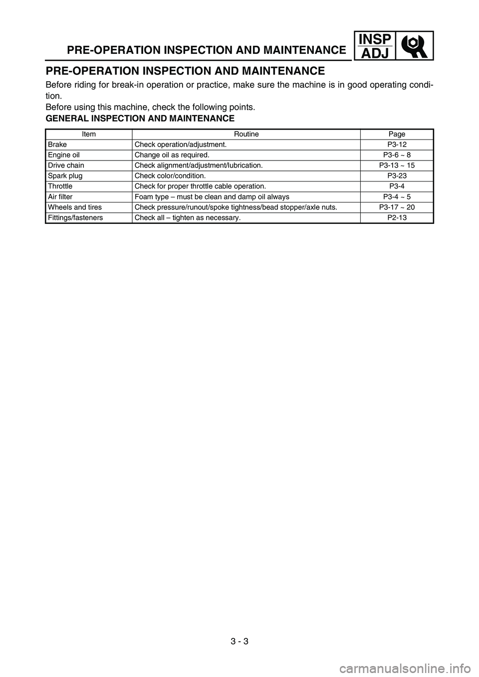
PRE-OPERATION INSPECTION AND MAINTENANCE
PRE-OPERATION INSPECTION AND MAINTENANCE
Before riding for break-in operation or practice, make sure the machine is in good operating condi-
tion.
Before using this machine, check the following points.
GENERAL INSPECTION AND MAINTENANCE
Item Routine Page
Brake Check operation/adjustment. P3-12
Engine oil Change oil as required. P3-6 ~ 8
Drive chain Check alignment/adjustment/lubrication. P3-13 ~ 15
Spark plug Check color/condition. P3-23
Throttle Check for proper throttle cable operation. P3-4
Air filter Foam type – must be clean and damp oil always P3-4 ~ 5
Wheels and tires Check pressure/runout/spoke tightness/bead stopper/axle nuts. P3-17 ~ 20
Fittings/fasteners Check all – tighten as necessary. P2-13