ACURA TL 1995 Service Repair Manual
Manufacturer: ACURA, Model Year: 1995, Model line: TL, Model: ACURA TL 1995Pages: 1771, PDF Size: 62.49 MB
Page 1541 of 1771
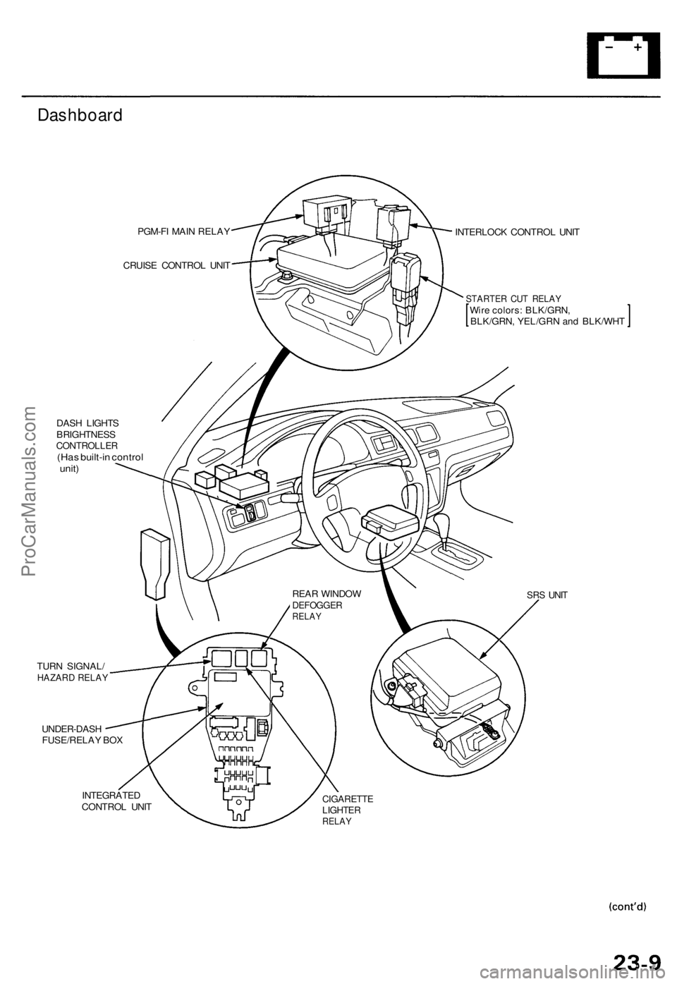
Dashboard
PGM-FI MAI N RELA Y
CRUIS E CONTRO L UNI T
DAS H LIGHT S
BRIGHTNES S
CONTROLLE R(Has built-i n contro lunit)
TUR N SIGNAL /HAZARD RELA Y
UNDER-DAS H
FUSE/RELA Y BO X INTERLOC
K CONTRO L UNI T
STARTE R CU T RELA YWire colors : BLK/GRN ,BLK/GRN, YEL/GR N an d BLK/WH T
SRS UNI T
INTEGRATE D
CONTRO L UNI TCIGARETT ELIGHTERRELAY
REAR WINDO WDEFOGGE RRELAY
ProCarManuals.com
Page 1542 of 1771
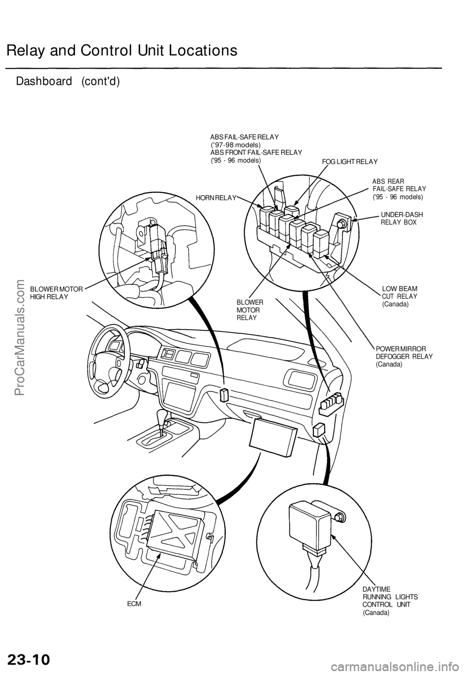
Relay and Control Unit Locations
Dashboard (cont'd)
ABS FAIL-SAFE RELAY
('97-98 models)
ABS FRONT FAIL-SAFE RELAY
('95 - 96 models)
FOG LIGHT RELAY
BLOWER MOTOR
HIGH RELAY
ABS REAR
FAIL-SAFE RELAY
('95 - 96 models)
UNDER-DASH
RELAY BOX
LOW BEAM
CUT RELAY
(Canada)
POWER MIRROR
DEFOGGER RELAY
(Canada)
ECM
DAYTIME
RUNNING LIGHTS
CONTROL UNIT
(Canada)
BLOWER
MOTOR
RELAY
HORN RELAYProCarManuals.com
Page 1543 of 1771
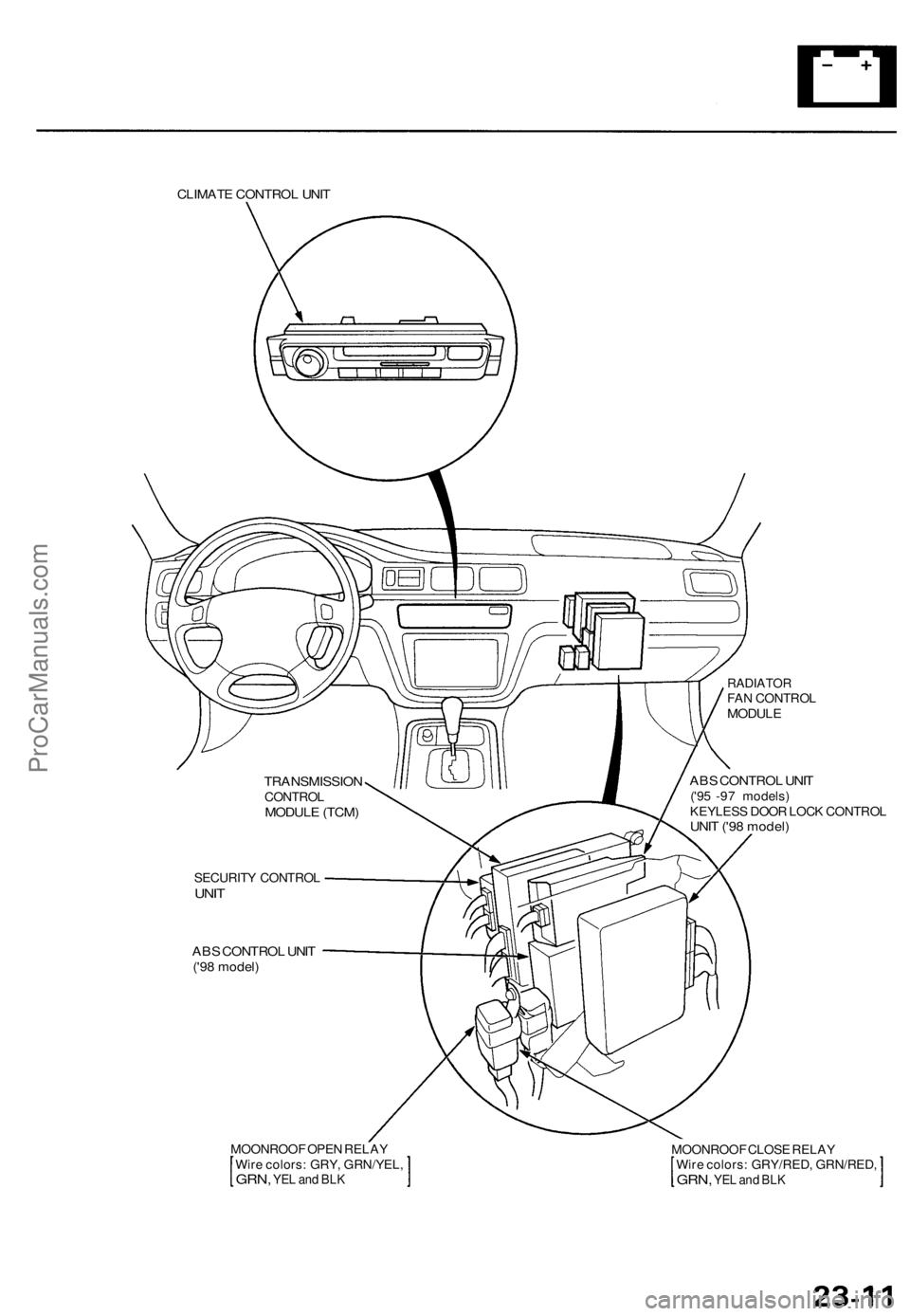
CLIMATE CONTROL UNIT
RADIATOR
FAN CONTROL
MODULE
ABS CONTROL UNIT
('95 -97 models)
KEYLESS DOOR LOCK CONTROL
UNIT ('98 model)
SECURITY CONTROL
UNIT
ABS CONTROL UNIT
('98 model)
MOONROOF OPEN RELAY
Wire colors: GRY, GRN/YEL,
GRN,
YEL and BLK
MOONROOF CLOSE RELAY
Wire colors: GRY/RED, GRN/RED,
GRN,
YEL and BLK
TRANSMISSION
CONTROL
MODULE (TCM)ProCarManuals.com
Page 1544 of 1771
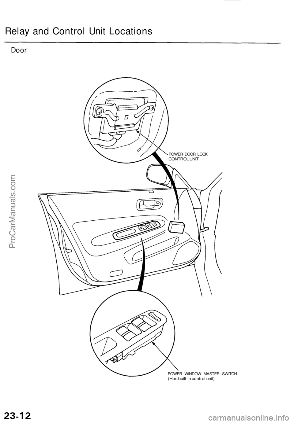
Relay and Control Unit Locations
Door
POWER WINDOW MASTER SWITCH
(Has built-in control unit)
POWER DOOR LOCK
CONTROL UNITProCarManuals.com
Page 1545 of 1771
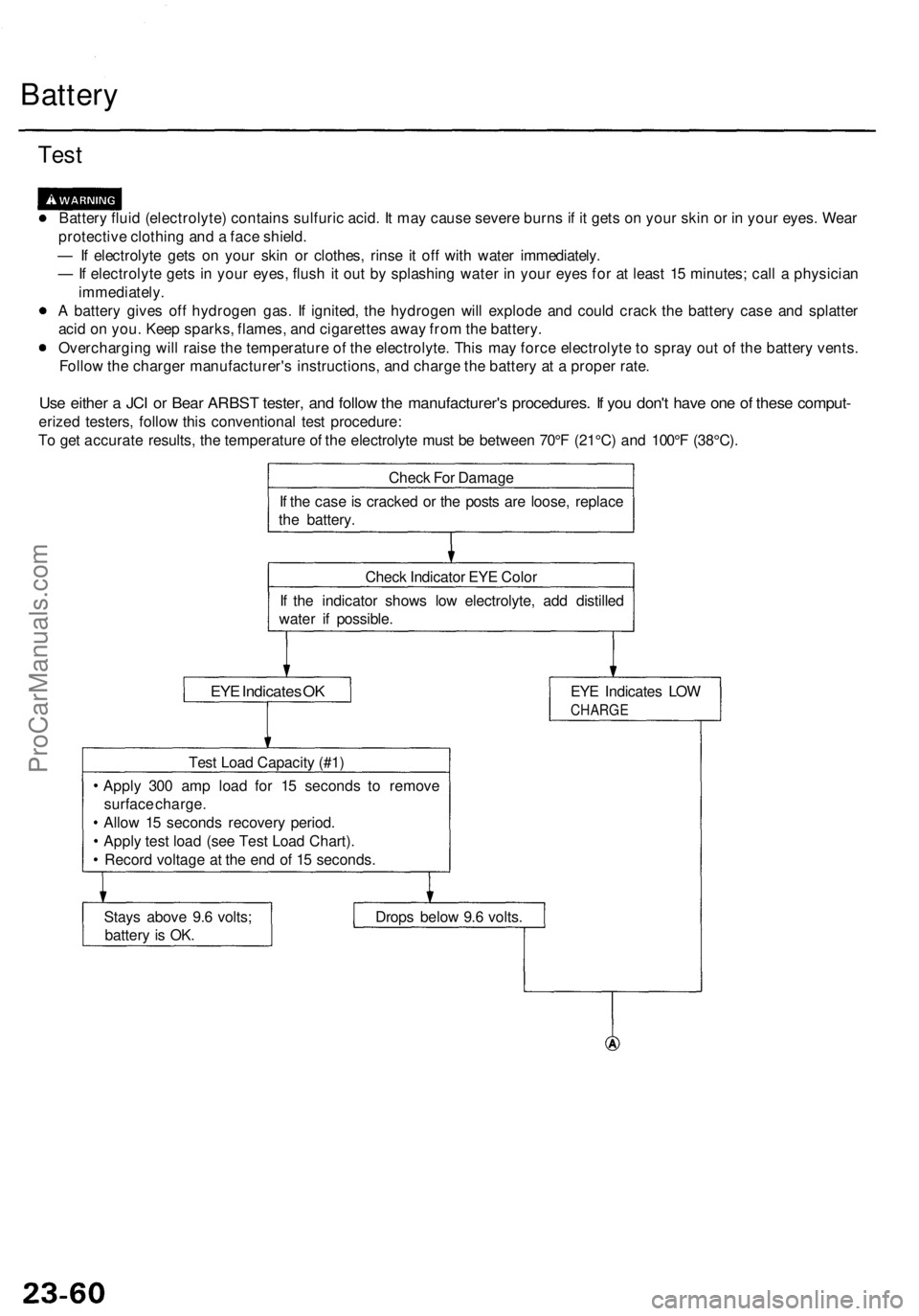
Battery
Test
Battery fluid (electrolyte) contains sulfuric acid. It may cause severe burns if it gets on your skin or in your eyes. Wear
protective clothing and a face shield.
— If electrolyte gets on your skin or clothes, rinse it off with water immediately.
— If electrolyte gets in your eyes, flush it out by splashing water in your eyes for at least 15 minutes; call a physician
immediately.
A battery gives off hydrogen gas. If ignited, the hydrogen will explode and could crack the battery case and splatter
acid on you. Keep sparks, flames, and cigarettes away from the battery.
Overcharging will raise the temperature of the electrolyte. This may force electrolyte to spray out of the battery vents.
Follow the charger manufacturer's instructions, and charge the battery at a proper rate.
Use either a JCI or Bear ARBST tester, and follow the manufacturer's procedures. If you don't have one of these comput-
erized testers, follow this conventional test procedure:
To get accurate results, the temperature of the electrolyte must be between 70°F (21°C) and 100°F (38°C).
Check For Damage
If the case is cracked or the posts are loose, replace
the battery.
Check Indicator EYE Color
If the indicator shows low electrolyte, add distilled
water if possible.
EYE Indicates OK
EYE Indicates LOW
CHARGE
Test Load Capacity (#1)
Apply 300 amp load for 15 seconds to remove
surface charge.
Allow 15 seconds recovery period.
Apply test load (see Test Load Chart).
Record voltage at the end of 15 seconds.
Stays above 9.6 volts;
battery is OK.
Drops below 9.6 volts.ProCarManuals.com
Page 1546 of 1771
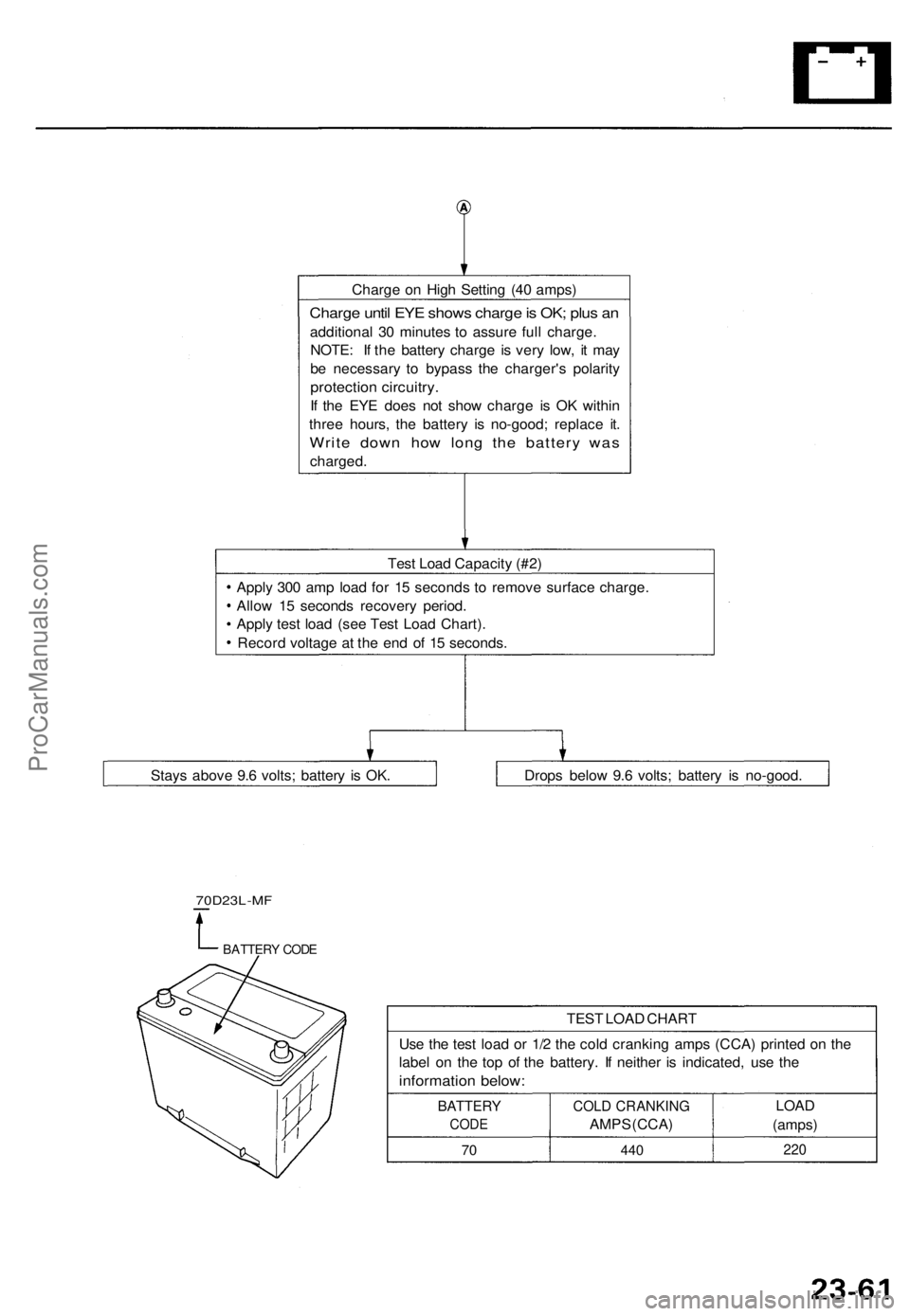
Charge on High Setting (40 amps)
Charge until EYE shows charge is OK; plus an
additional 30 minutes to assure full charge.
NOTE: If the battery charge is very low, it may
be necessary to bypass the charger's polarity
protection circuitry.
If the EYE does not show charge is OK within
three hours, the battery is no-good; replace it.
Write down how long the battery was
charged.
Test Load Capacity (#2)
Apply 300 amp load for 15 seconds to remove surface charge.
Allow 15 seconds recovery period.
Apply test load (see Test Load Chart).
Record voltage at the end of 15 seconds.
70D23L-MF
BATTERY CODE
TEST LOAD CHART
Use the test load or 1/2 the cold cranking amps (CCA) printed on the
label on the top of the battery. If neither is indicated, use the
information below:
BATTERY
CODE
70
COLD CRANKING
AMPS (CCA)
440
LOAD
(amps)
220
Drops below 9.6 volts; battery is no-good.
Stays above 9.6 volts; battery is OK.ProCarManuals.com
Page 1547 of 1771
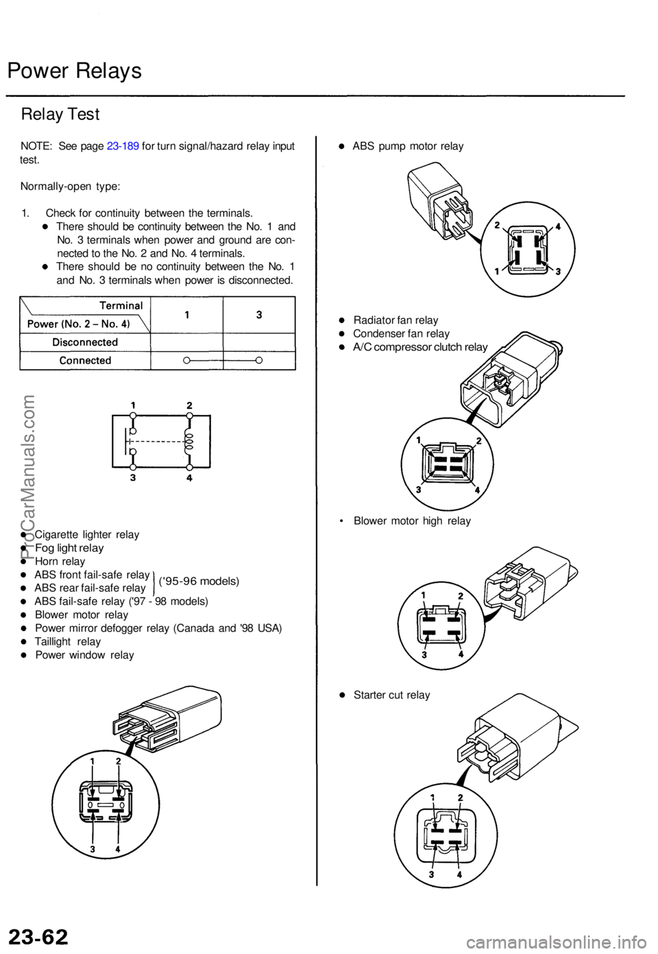
Power Relay s
Relay Tes t
NOTE : Se e pag e 23-18 9 fo r tur n signal/hazar d rela y inpu t
test .
Normally-ope n type :
1 . Chec k fo r continuit y betwee n th e terminals .
Ther e shoul d b e continuit y betwee n th e No . 1 an d
No . 3 terminal s whe n powe r an d groun d ar e con -
necte d to th e No . 2 an d No . 4 terminals .
Ther e shoul d b e n o continuit y betwee n th e No . 1
an d No . 3 terminal s whe n powe r i s disconnected .
('95-96 models )
Cigarett e lighte r rela y
Fog ligh t rela y
Horn rela y
AB S fron t fail-saf e rela y
AB S rea r fail-saf e rela y
AB S fail-saf e rela y ('9 7 - 9 8 models )
Blowe r moto r rela y
Powe r mirro r defogge r rela y (Canad a an d '9 8 USA )
Tailligh t rela y
Powe r windo w rela y AB
S pum p moto r rela y
Radiato r fa n rela y
Condense r fa n rela y
A/C compresso r clutc h rela y
• Blowe r moto r hig h rela y
Starte r cu t rela y
ProCarManuals.com
Page 1548 of 1771
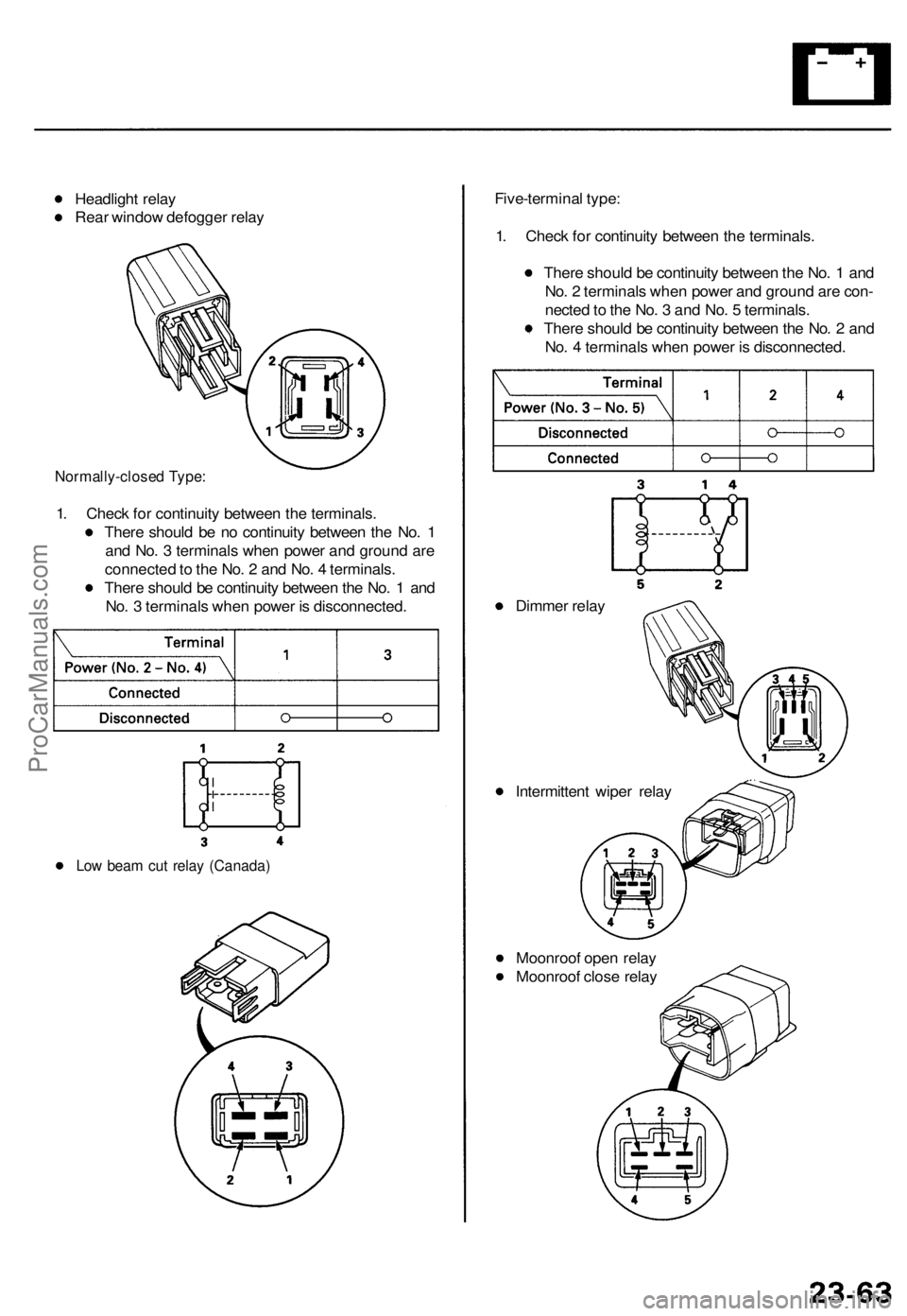
Headlight relay
Rear window defogger relay
Normally-closed Type:
1. Check for continuity between the terminals.
There should be no continuity between the No. 1
and No. 3 terminals when power and ground are
connected to the No. 2 and No. 4 terminals.
There should be continuity between the No. 1 and
No. 3 terminals when power is disconnected.
Low beam cut relay (Canada)
Five-terminal type:
1. Check for continuity between the terminals.
There should be continuity between the No. 1 and
No. 2 terminals when power and ground are con-
nected to the No. 3 and No. 5 terminals.
There should be continuity between the No. 2 and
No. 4 terminals when power is disconnected.
Dimmer relay
Intermittent wiper relay
Moonroof open relay
Moonroof close relayProCarManuals.com
Page 1549 of 1771
Under-dash Fuse/Rela y Bo x
Removal/Installatio n
SRS component s ar e locate d in thi s area . Revie w th e SR S
componen t locations , precautions , an d procedure s i n th e
SR S (sectio n 24 ) befor e performin g repair s o r service .
Removal :
1. Mak e sur e yo u hav e th e anti-thef t cod e fo r th e radio ,
the n writ e dow n th e frequencie s fo r th e radio' s pre -
se t buttons .
2 . Disconnec t th e batter y negativ e cable , the n disconnec t
th e positiv e cable , an d wai t a t leas t thre e minutes .
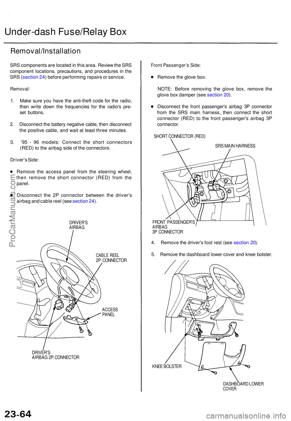
3 . '9 5 - 9 6 models : Connec t th e shor t connector s
(RED ) t o th e airba g sid e o f th e connectors .
Driver' s Side :
Remov e th e acces s pane l fro m th e steerin g wheel ,
the n remov e th e shor t connecto r (RED ) fro m th e
panel .
Disconnec t th e 2 P connecto r betwee n th e driver' s
airba g an d cabl e ree l (se e sectio n 24 ).
DRIVER' SAIRBAG
CABLE REE L2P CONNECTO R
ACCESSPANEL
DRIVER' SAIRBAG 2 P CONNECTO R
Front Passenger' s Side :
Remov e th e glov e box .
NOTE : Befor e removin g th e glov e box , remov e th e
glov e bo x dampe r (se e sectio n 20 ).
Disconnec t th e fron t passenger' s airba g 3 P connecto r
fro m th e SR S mai n harness , the n connec t th e shor t
connecto r (RED ) t o th e fron t passenger' s airba g 3 P
connector .
SHORT CONNECTO R (RED )
SRS MAI N HARNES S
FRONT PASSENGER' SAIRBAG3P CONNECTO R
4. Remov e th e driver' s foo t res t (se e sectio n 20 ).
5 . Remov e th e dashboar d lowe r cove r an d kne e bolster .
KNEE BOLSTE R
DASHBOARD LOWE R
COVER
ProCarManuals.com
Page 1550 of 1771
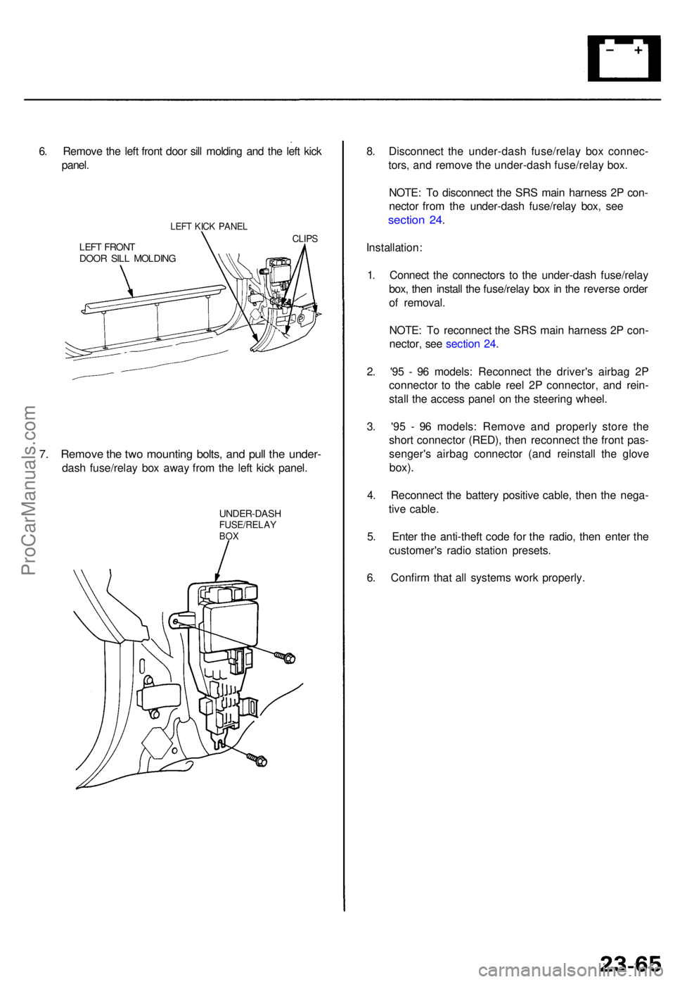
6. Remov e th e lef t fron t doo r sil l moldin g an d th e lef t kic k
panel .
LEFT KIC K PANE L
LEFT FRON TDOOR SIL L MOLDIN G
CLIPS
7. Remov e th e tw o mountin g bolts , an d pul l th e under -
dash fuse/rela y bo x awa y fro m th e lef t kic k panel .
UNDER-DAS HFUSE/RELAYBOX
8. Disconnec t th e under-das h fuse/rela y bo x connec -
tors , an d remov e th e under-das h fuse/rela y box .
NOTE : T o disconnec t th e SR S mai n harnes s 2 P con -
necto r fro m th e under-das h fuse/rela y box , se e
sectio n 24 .
Installation :
1 . Connec t th e connector s t o th e under-das h fuse/rela y
box , the n instal l th e fuse/rela y bo x in th e revers e orde r
o f removal .
NOTE : T o reconnec t th e SR S mai n harnes s 2 P con -
nector , se e sectio n 24 .
2 . '9 5 - 9 6 models : Reconnec t th e driver' s airba g 2 P
connecto r t o th e cabl e ree l 2 P connector , an d rein -
stal l th e acces s pane l o n th e steerin g wheel .
3 . '9 5 - 9 6 models : Remov e an d properl y stor e th e
shor t connecto r (RED) , the n reconnec t th e fron t pas -
senger' s airba g connecto r (an d reinstal l th e glov e
box).
4. Reconnec t th e batter y positiv e cable , the n th e nega -
tiv e cable .
5 . Ente r th e anti-thef t cod e fo r th e radio , the n ente r th e
customer' s radi o statio n presets .
6 . Confir m tha t al l system s wor k properly .
ProCarManuals.com