ACURA TL 1995 Service Repair Manual
Manufacturer: ACURA, Model Year: 1995, Model line: TL, Model: ACURA TL 1995Pages: 1771, PDF Size: 62.49 MB
Page 1551 of 1771
Ignition Switc h
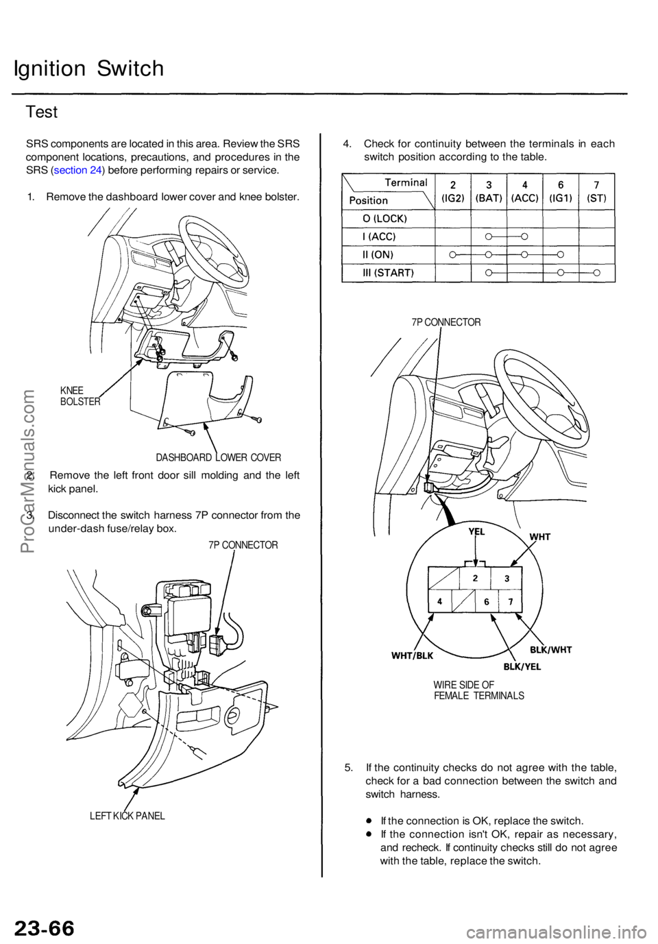
Test
SRS component s ar e locate d in thi s area . Revie w th e SR S
componen t locations , precautions , an d procedure s i n th e
SR S (sectio n 24 ) befor e performin g repair s o r service .
1 . Remov e th e dashboar d lowe r cove r an d kne e bolster .
KNEEBOLSTE R
DASHBOAR D LOWE R COVE R
2. Remov e th e lef t fron t doo r sil l moldin g an d th e lef t
kic k panel .
3 . Disconnec t th e switc h harnes s 7 P connecto r fro m th e
under-das h fuse/rela y box .
7P CONNECTO R
LEF T KIC K PANE L
4. Chec k fo r continuit y betwee n th e terminal s i n eac h
switc h positio n accordin g t o th e table .
7P CONNECTO R
WIR E SID E O F
FEMAL E TERMINAL S
5. I f th e continuit y check s d o no t agre e wit h th e table ,
chec k fo r a ba d connectio n betwee n th e switc h an d
switc h harness .
I f th e connectio n is OK , replac e th e switch .
I f th e connectio n isn' t OK , repai r a s necessary ,
an d recheck . I f continuit y check s stil l d o no t agre e
wit h th e table , replac e th e switch .
ProCarManuals.com
Page 1552 of 1771
Steering Loc k Replacemen t
SRS component s ar e locate d in thi s area . Revie w th e SR S
componen t locations , precautions , an d procedure s i n th e
SR S (sectio n 24 ) befor e performin g repair s o r service .
Removal :
1 . Mak e sur e yo u hav e th e anti-thef t cod e fo r th e radio ,
then writ e dow n th e frequencie s fo r th e radio' s pre -
set buttons .
2. Disconnec t th e batter y negativ e cable , the n disconnec t
th e positiv e cable , an d wai t a t leas t thre e minutes .
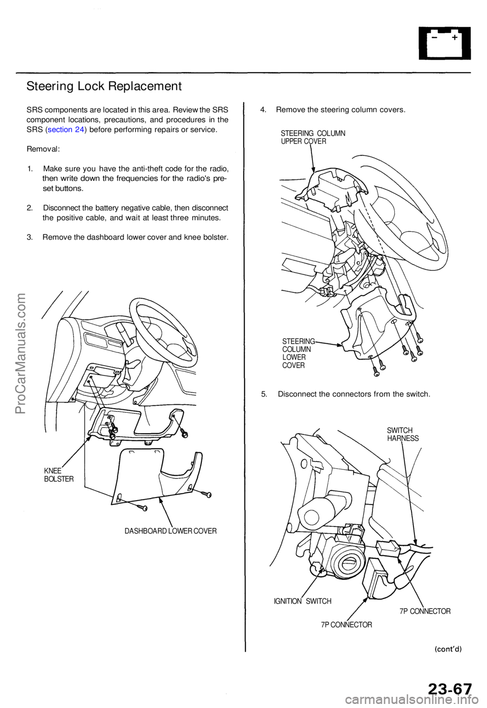
3 . Remov e th e dashboar d lowe r cove r an d kne e bolster .
KNEEBOLSTE R
DASHBOARD LOWE R COVE R
4. Remov e th e steerin g colum n covers .
STEERIN G COLUM NUPPER COVE R
STEERIN GCOLUMNLOWERCOVER
5. Disconnec t th e connector s fro m th e switch .
SWITCH
HARNES S
IGNITIO N SWITC H
7 P CONNECTO R7
P CONNECTO R
ProCarManuals.com
Page 1553 of 1771
Ignition Switch
Steering Lock Replacement (cont'd)
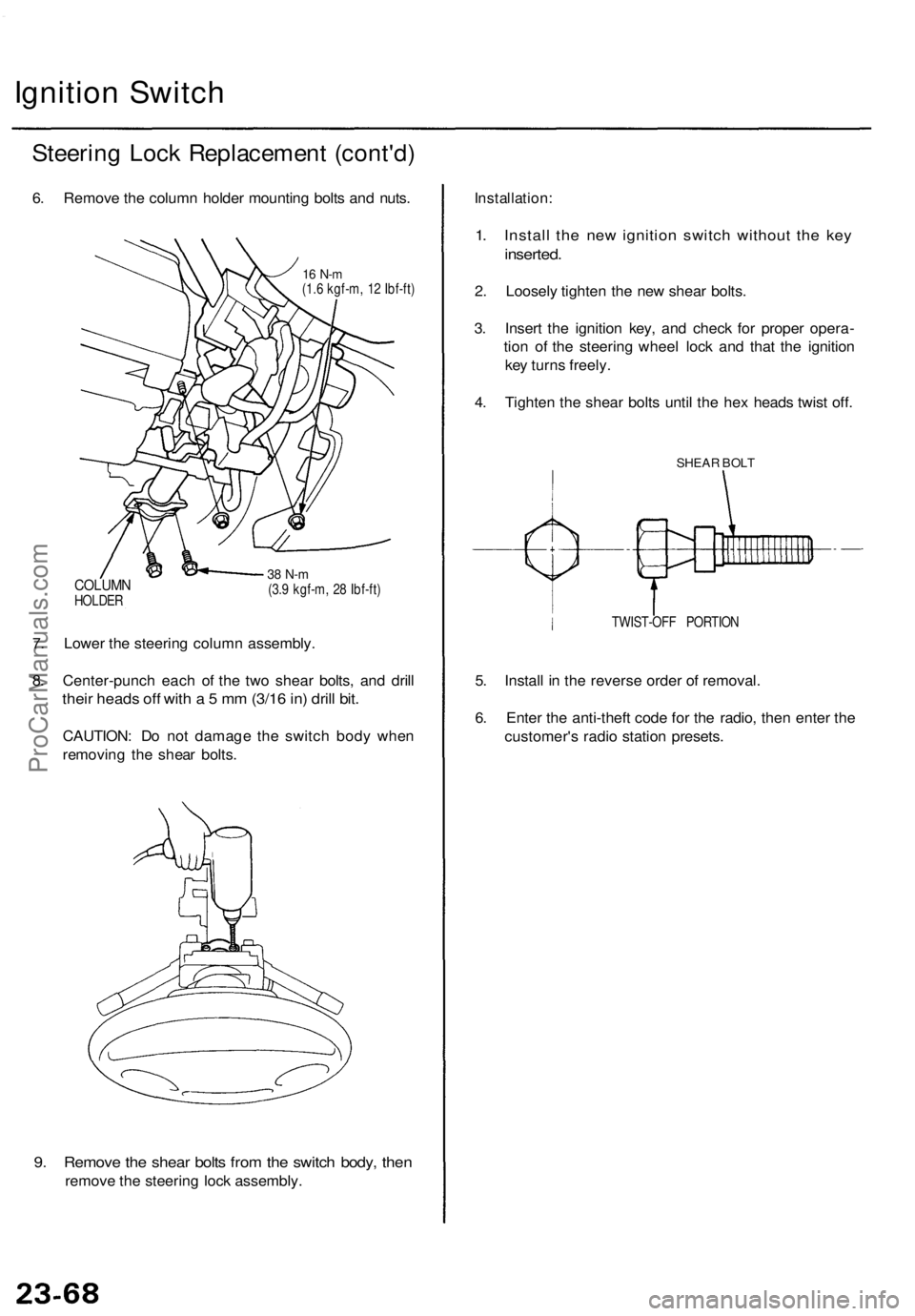
6. Remove the column holder mounting bolts and nuts.
16 N-m
(1.6 kgf-m, 12 Ibf-ft)
COLUMN
HOLDER
38 N-m
(3.9 kgf-m, 28 Ibf-ft)
7. Lower the steering column assembly.
8. Center-punch each of the two shear bolts, and drill
their heads off with a 5 mm (3/16 in) drill bit.
CAUTION: Do not damage the switch body when
removing the shear bolts.
9. Remove the shear bolts from the switch body, then
remove the steering lock assembly.
Installation:
1. Install the new ignition switch without the key
inserted.
2. Loosely tighten the new shear bolts.
3. Insert the ignition key, and check for proper opera-
tion of the steering wheel lock and that the ignition
key turns freely.
4. Tighten the shear bolts until the hex heads twist off.
SHEAR BOLT
TWIST-OFF PORTION
5. Install in the reverse order of removal.
6. Enter the anti-theft code for the radio, then enter the
customer's radio station presets.ProCarManuals.com
Page 1554 of 1771
Electrical Switc h Replacemen t
SRS component s ar e locate d in thi s area . Revie w th e SR S
componen t locations , precautions , an d procedure s in th e
SR S (sectio n 24 ) befor e performin g repair s o r service .
1 . Mak e sur e yo u hav e th e anti-thef t cod e fo r th e radio ,
the n writ e dow n th e frequencie s fo r th e radio' s pre -
set buttons .
2. Disconnec t th e batter y negativ e cable , the n discon -
nec t th e positiv e cable , an d wai t a t leas t thre e min -
utes .
3 . Remov e th e dashboar d lowe r cove r an d kne e bolste r
(se e pag e 23-67 ).
4 . Remov e th e steerin g colum n cover s (se e pag e 23-67 ).
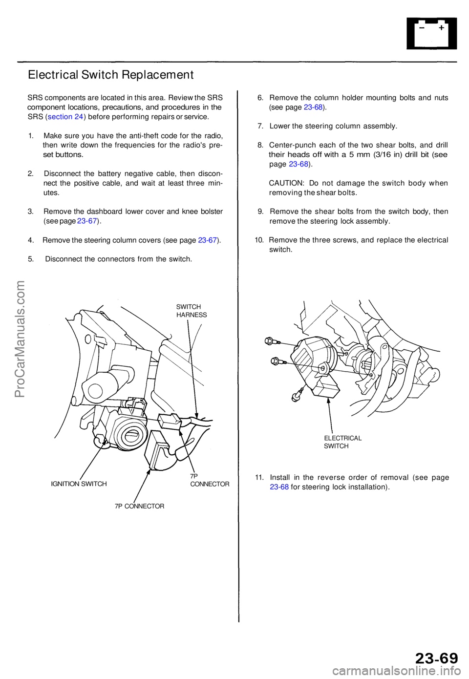
5 . Disconnec t th e connector s fro m th e switch .
SWITCHHARNES S
IGNITION SWITC H7PCONNECTO R
7 P CONNECTO R
6. Remov e th e colum n holde r mountin g bolt s an d nut s
(se e pag e 23-68 ).
7 . Lower the steerin g colum n assembly .
8 . Center-punc h eac h o f th e tw o shea r bolts , an d dril l
their head s of f wit h a 5 mm (3/1 6 in ) dril l bi t (se e
pag e 23-68 ).
CAUTION : D o no t damag e th e switc h bod y whe n
removin g th e shea r bolts .
9 . Remov e th e shea r bolt s fro m th e switc h body , the n
remov e th e steerin g loc k assembly .
10 . Remov e th e thre e screws , an d replac e th e electrica l
switch .
ELECTRICA LSWITCH
11. Instal l i n th e revers e orde r o f remova l (se e pag e
23-6 8 fo r steerin g loc k installation) .
ProCarManuals.com
Page 1555 of 1771
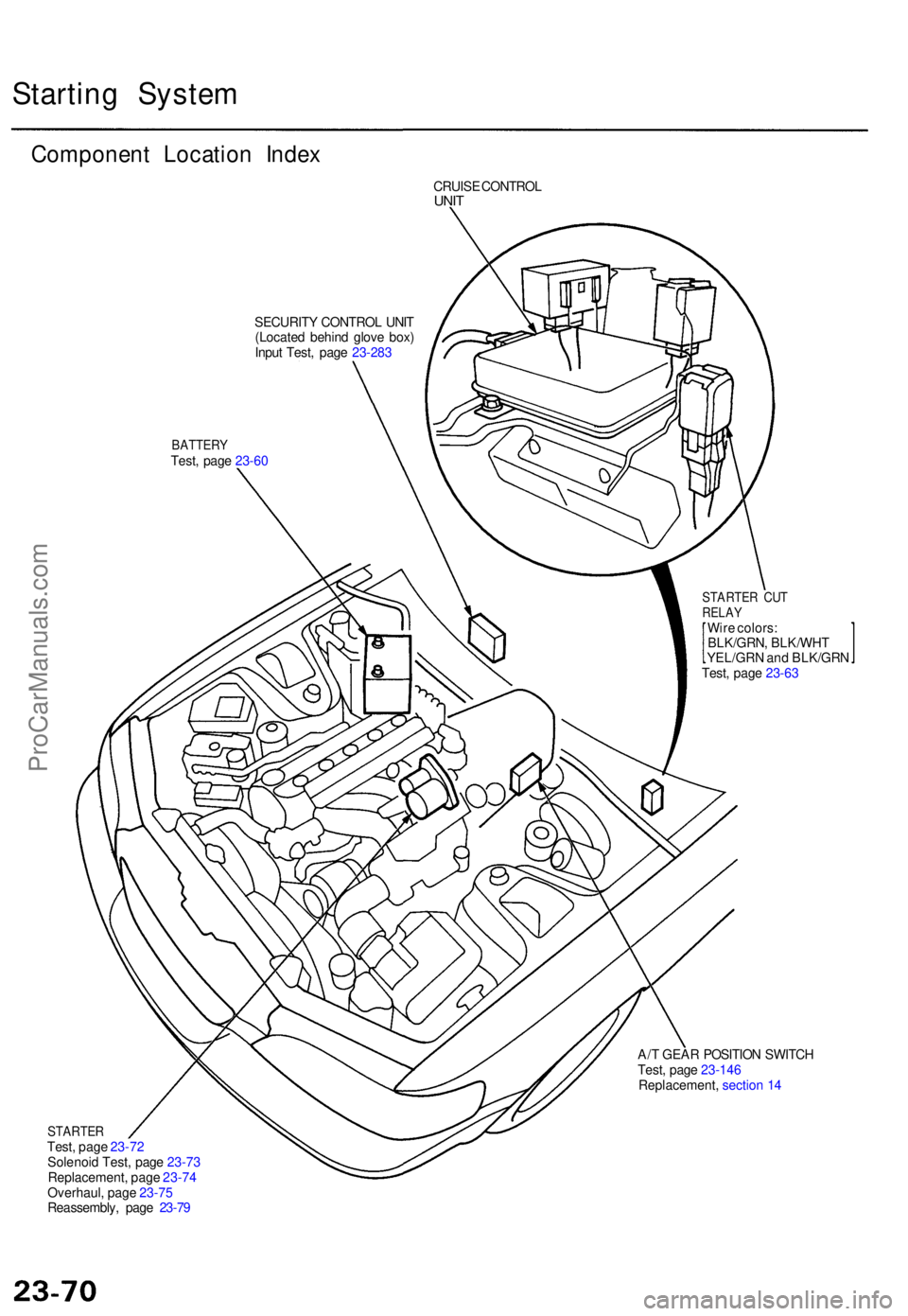
Starting Syste m
Componen t Locatio n Inde x
CRUIS E CONTRO LUNIT
SECURIT Y CONTRO L UNI T
(Locate d behin d glov e box )
Inpu t Test , pag e 23-28 3
BATTER YTest, pag e 23-6 0
STARTE R CU TRELA YWire colors :
BLK/GRN , BLK/WH T
YEL/GR N an d BLK/GR N
Test , pag e 23-6 3
A/ T GEA R POSITIO N SWITC H
Test , pag e 23-14 6
Replacement , sectio n 1 4
STARTE RTest, pag e 23-7 2
Solenoi d Test , pag e 23-7 3
Replacement , pag e 23-7 4
Overhaul , pag e 23-7 5
Reassembly , pag e 23-7 9
ProCarManuals.com
Page 1556 of 1771
Starting Syste m
Starter Tes t
NOTE : Th e ai r temperatur e mus t b e betwee n 5 9 an d
100° F (1 5 an d 38°C ) befor e testing .
Recommende d Procedure :
Use a starte r syste m tester .
Connec t an d operat e th e equipmen t i n accordanc e
wit h th e manufacturer' s instructions .
Tes t an d troubleshoo t a s described .
Alternate Procedure :
Use followin g equipment :
— Ammeter , 0 - 400 A
— Voltmeter , 0 - 20 V (accurat e withi n 0. 1 volt )
— Tachometer , 0 - 1,20 0 rp m
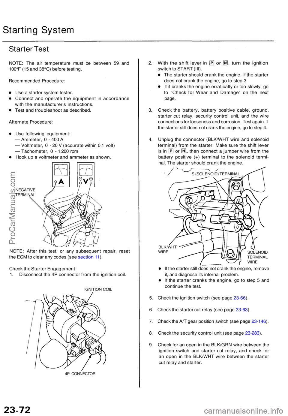
Hoo k u p a voltmete r an d ammete r a s shown .
NEGATIV ETERMINA L
NOTE: Afte r thi s test , o r an y subsequen t repair , rese t
th e EC M to clea r an y code s (se e sectio n 11 ).
Chec k th e Starte r Engagemen t
1 . Disconnec t th e 4 P connecto r fro m th e ignitio n coil .
IGNITIO N COI L
4P CONNECTO R
2. Wit h th e shif t leve r i n o r , turn th e ignitio n
switch to STAR T (III) .
Th e starte r shoul d cran k th e engine . I f th e starte r
doe s no t cran k th e engine , g o to ste p 3 .
I f i t crank s th e engin e erraticall y o r to o slowly , g o
t o "Chec k fo r Wea r an d Damage " o n th e nex t
page .
3. Chec k th e battery , batter y positiv e cable , ground ,
starte r cu t relay , securit y contro l unit , an d th e wir e
connection s fo r loosenes s an d corrosion . Tes t again . I f
th e starte r stil l doe s no t cran k th e engine , g o to ste p 4 .
4 . Unplu g th e connecto r (BLK/WH T wir e an d solenoi d
terminal ) fro m th e starter . Mak e sur e th e shif t leve r
is i n o r , then connec t a jumpe r wir e fro m th e
batter y positiv e (+ ) termina l t o th e solenoi d termi -
nal . Th e starte r shoul d cran k th e engine .
I f th e starte r stil l doe s no t cran k th e engine , remov e
it , an d diagnos e it s interna l problem .
I f th e starte r crank s th e engine , g o t o ste p 5 an d
continu e th e test .
5 . Chec k th e ignitio n switc h (se e pag e 23-66 ).
6 . Chec k th e starte r cu t rela y (se e pag e 23-63 ).
7 . Chec k th e A/ T gea r positio n switc h (se e pag e 23-146 ).
8 . Chec k th e securit y contro l uni t (se e pag e 23-283 ).
9 . Chec k fo r a n ope n in th e BLK/GR N wir e betwee n th e
ignitio n switc h an d starte r cu t relay , an d chec k fo r
a n ope n i n th e BLK/WH T wir e betwee n th e starte r
cu t rela y an d starter .
SOLENOI DTERMINA LWIRE
BLK/WH TWIRE
S (SOLENOID ) TERMINA L
ProCarManuals.com
Page 1557 of 1771
Check for Wear and Damage
The starter should crank the engine smoothly and steadily.
If the starter engages, but cranks the engine erratically,
remove it, and inspect the starter drive gear and torque
converter ring gear for damage.
Check the drive gear overrunning clutch for binding or
slipping when the armature is rotated with the drive
gear held. If the clutch is damaged, replace the clutch
assembly.
Check Cranking Voltage and Current Draw
Cranking voltage should be no less than 8.5 volts.
Current draw should be no more than 380 amperes.
If cranking voltage is too low, or current draw too high,
check for:
Dead or low battery
Open circuit in starter armature commutator segments
Starter armature dragging
Shorted armature winding
Excessive drag in engine
Check Cranking rpm
Engine speed during cranking should be above 100 rpm.
If speed is too low, check for:
Loose battery or starter terminals
Excessively worn starter brushes
Open circuit in commutator segments
Dirty or damaged helical spline or drive gear
Defective drive gear overrunning clutch
Check Starter Disengagement
With the shift lever in turn the ignition switch to
"START (III)", and release to "ON (II)". The starter drive
gear should disengage from the drive plate/ring gear
when you release the key.
If the drive gear hangs up on the drive plate/ring gear,
check for:
• Solenoid plunger and switch malfunction
• Dirty drive gear assembly or damaged overrunning
clutchProCarManuals.com
Page 1558 of 1771
Starter Solenoid Test
1. Make sure you have the anti-theft code for the
radio, then write down the frequencies for the
radio's preset buttons.
2. Disconnect the battery negative cable, then discon-
nect the positive cable.
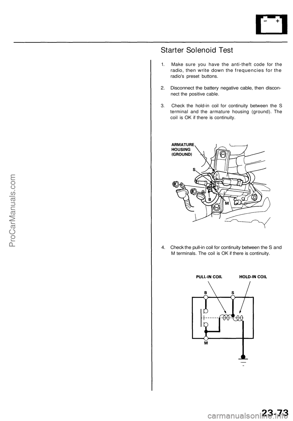
3. Check the hold-in coil for continuity between the S
terminal and the armature housing (ground). The
coil is OK if there is continuity.
4. Check the pull-in coil for continuity between the S and
M terminals. The coil is OK if there is continuity.ProCarManuals.com
Page 1559 of 1771
Starting Syste m
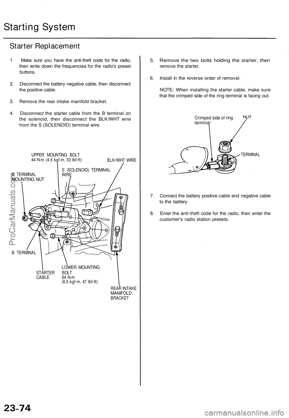
Starter Replacemen t
1. Mak e sur e yo u hav e th e anti-thef t cod e fo r th e radio ,
the n writ e dow n th e frequencie s fo r th e radio' s prese t
buttons .
2 . Disconnec t th e batter y negativ e cable , the n disconnec t
th e positiv e cable .
3 . Remov e th e rea r intak e manifol d bracket .
4 . Disconnec t th e starte r cabl e fro m th e B termina l o n
th e solenoid , the n disconnec t th e BLK/WH T wir e
fro m th e S (SOLENOID ) termina l wire .
UPPE R MOUNTIN G BOL T
4 4 N- m (4. 5 kgf-m , 3 3 Ibf-ft )
BLK/WHT WIR E
B TERMINA L
MOUNTING NU T
S (SOLENOID ) TERMINA LWIRE
B TERMINA L
LOWER MOUNTIN G
STARTER BOL T
CABL E 6 4 N- m
(6. 5 kgf-m , 4 7 Ibf-ft )
REAR INTAK E
MANIFOL DBRACKET
5. Remov e th e tw o bolt s holdin g th e starter , the n
remov e th e starter .
6 . Instal l i n th e revers e orde r o f removal .
NOTE : Whe n installin g th e starte r cable , mak e sur e
tha t th e crimpe d sid e o f th e rin g termina l i s facin g out .
Crimpe d sid e o f rin gtermina l
NUT
TERMINA L
7. Connec t th e batter y positiv e cabl e an d negativ e cabl e
t o th e battery .
8 . Ente r th e anti-thef t cod e fo r th e radio , the n ente r th e
customer' s radi o statio n presets .
ProCarManuals.com
Page 1560 of 1771
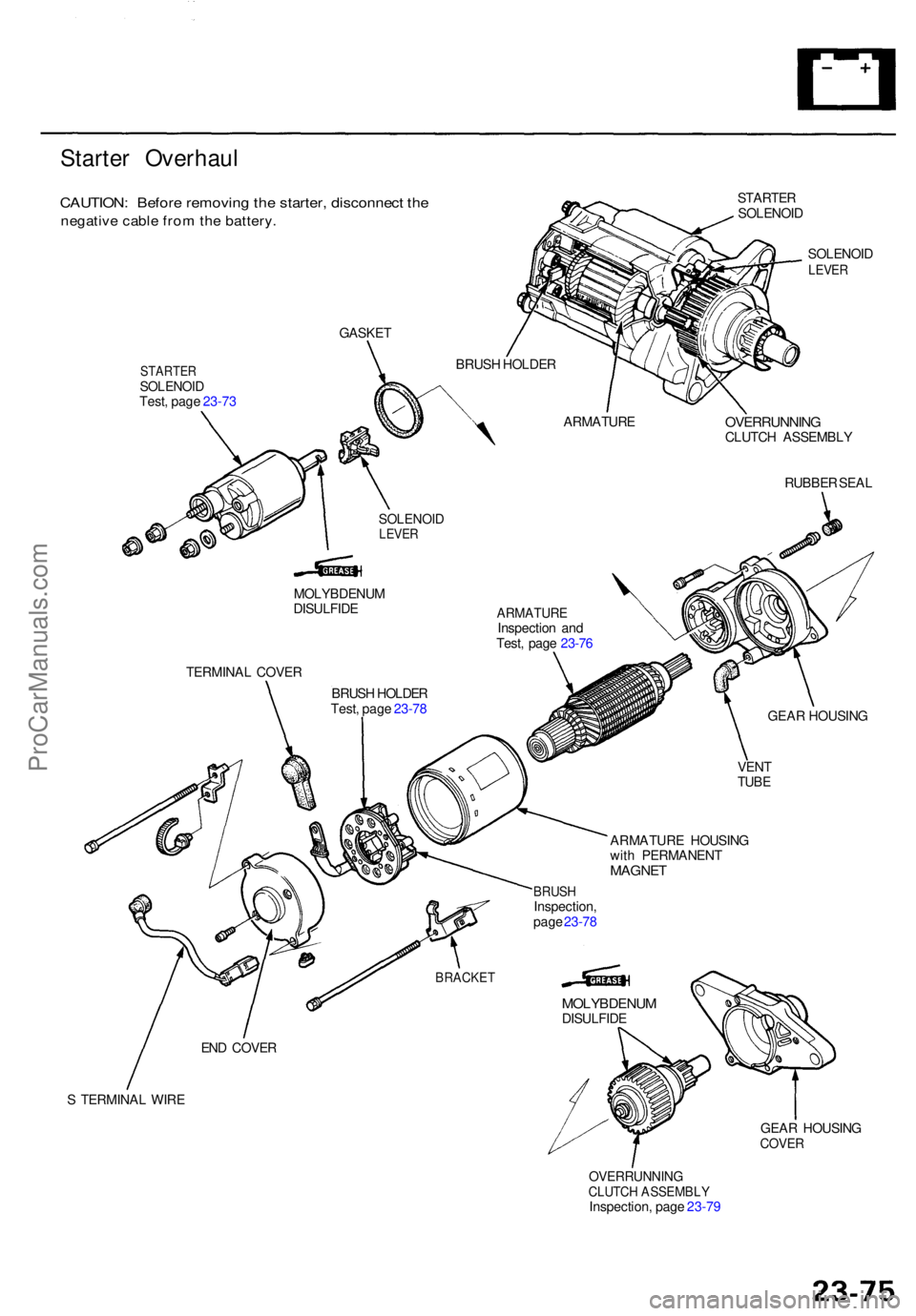
Starter Overhau l
CAUTION: Befor e removin g th e starter , disconnec t th e
negativ e cabl e fro m th e battery .
STARTE R
SOLENOI D
SOLENOI D
LEVER
STARTE RSOLENOI DTest, pag e 23-7 3
OVERRUNNIN GCLUTCH ASSEMBL Y
RUBBE R SEA L
MOLYBDENU M
DISULFID E
TERMINA L COVE R
BRUSH HOLDE R
Test , pag e 23-7 8
ARMATUR EInspection an d
Test , pag e 23-7 6
ARMATUR E HOUSIN G
wit h PERMANEN T
MAGNET
GEAR HOUSIN G
VEN T
TUBE
S TERMINA L WIR E
GEAR HOUSIN G
COVER
OVERRUNNIN GCLUTCH ASSEMBL YInspection, pag e 23-7 9
GASKE
T
BRUSH HOLDE R
ARMATUR E
SOLENOIDLEVER
BRUS HInspection ,
pag e 23-7 8
BRACKE T
END COVE R
MOLYBDENU MDISULFIDE
ProCarManuals.com