DATSUN 210 1979 Service Manual
Manufacturer: DATSUN, Model Year: 1979, Model line: 210, Model: DATSUN 210 1979Pages: 548, PDF Size: 28.66 MB
Page 201 of 548
INSTALLATION
Install
in
the
reverse
order
of
re
moval
observing
the
following
Note
When
inslal1ing
be
sure
to
check
thaI
electrical
harnesses
are
connected
ly
1
When
installing
first
secure
rear
engine
mounting
member
to
body
2
Refer
to
applicable
section
when
installing
and
adjusting
any
parts
Adjust
clutch
pedal
free
travel
Re
fer
to
Clutch
Pedal
Free
Travel
Section
CL
for
installation
and
adjustment
Adjust
accelerator
control
system
Refer
to
Engine
Control
System
Section
FE
for
adjustment
For
installation
of
air
conditioner
compressor
and
belt
adjustment
Refer
to
Idler
Pulley
and
Com
pressor
Drive
Belt
for
adjustment
of
belt
tension
3
When
installing
exhaust
front
tube
on
exhaust
manifold
be
sure
to
use
new
gasket
4
When
installing
hood
following
engine
installation
be
sure
that
it
is
properly
centered
and
that
hood
lock
operates
securely
Refer
to
Hood
See
tion
BF
for
adjustment
Engine
Removal
Installation
ENGINE
MOUNTING
INSULATOR
FRONT
INSULATOR
Removal
Disconnect
battery
ground
cable
2
Suspend
engine
with
wire
or
chain
3
Remove
front
engine
mounting
insulator
lower
and
upper
nuts
on
both
sides
4
Make
sure
that
wire
or
chain
used
to
suspend
engine
is
positioned
prqper
ly
so
that
no
load
is
applied
to
insulators
and
remove
nuts
complete
ly
5
Lift
up
engine
and
separate
in
sulators
from
engine
mounting
rack
ets
Inspection
If
there
is
damage
deterioration
or
separation
of
bounded
surface
re
place
Installation
Install
front
insulators
in
reverse
sequence
of
removal
noting
the
fol
lowing
1
Do
not
confuse
right
and
left
insulators
R
right
side
or
L
left
side
identification
mark
is
stamp
ed
on
each
insulator
2
Install
front
insulator
so
that
ER
5
position
pin
is
projected
upward
3
Tighten
the
bolts
and
nut
correct
ly
and
securely
See
Fig
ER
I
REAR
INSULATOR
Removal
l
Support
transmission
weight
with
ajack
2
Remove
nuts
securing
rear
engine
mounting
insulator
to
mounting
mem
ber
3
Remove
bolts
connecting
rear
en
gine
mounting
insulator
to
transmis
sion
reaf
extension
housing
4
Jack
up
the
transmission
a
little
and
remove
insulator
Inspection
If
there
is
damage
deterioration
or
separation
of
mating
surface
replace
Installation
Install
rear
engine
mounting
mem
ber
and
insulator
in
reverse
order
of
removal
noting
the
following
I
Install
insulator
in
place
so
that
direction
of
mounted
insulator
is
same
as
that
in
Fig
ER
2
Tighten
nuts
and
bolts
correctly
and
securely
As
for
tightening
torque
see
Fig
ER
l
Page 202 of 548
Engine
Removal
Installation
SERVICE
DATA
AND
SPECIFICATIONS
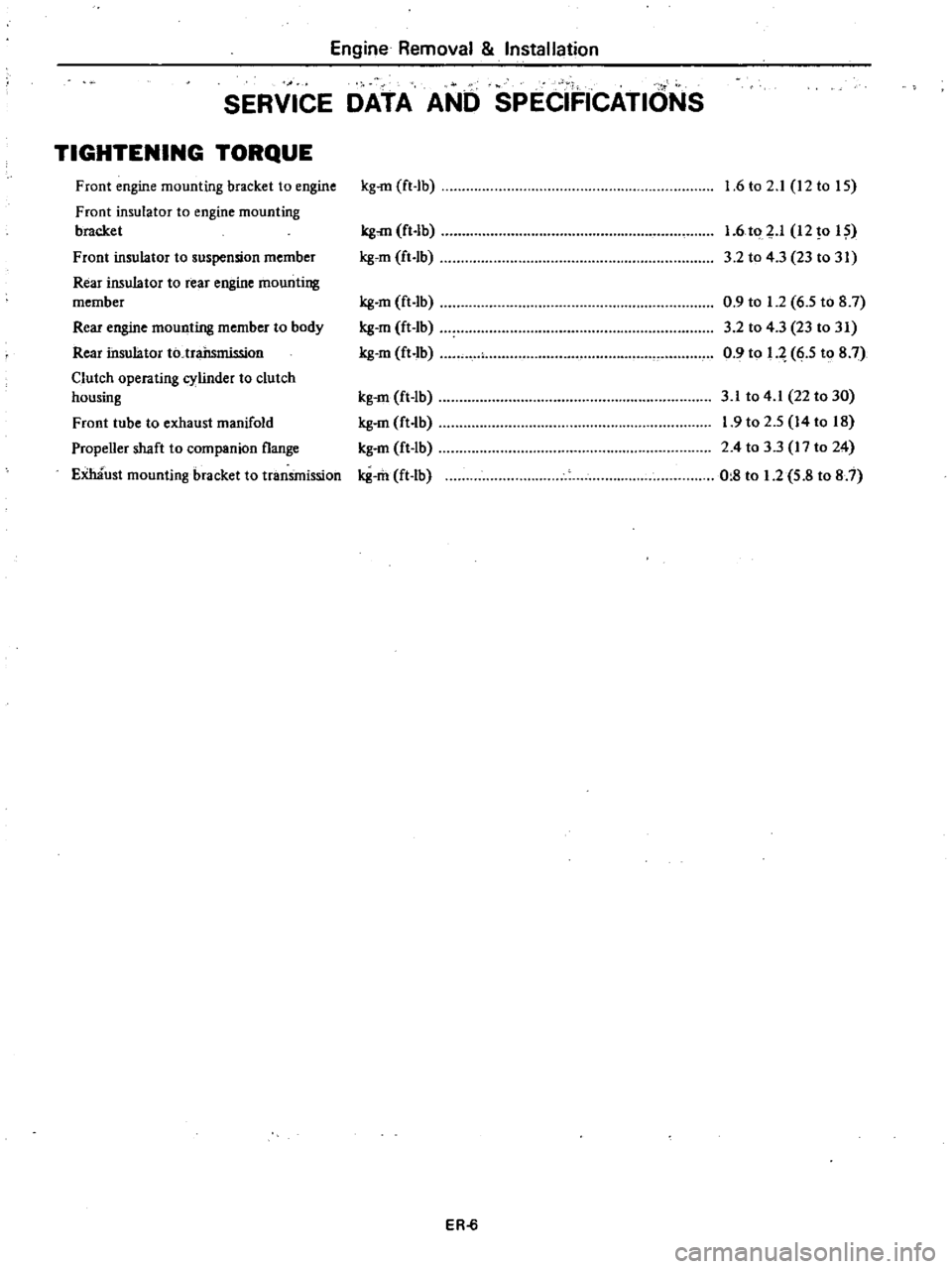
TIGHTENING
TORQUE
Front
engine
mounting
bracket
to
engine
Front
insulator
to
engine
mounting
bracket
Front
insulator
to
suspension
member
Rear
insulator
to
rear
engine
mounting
member
Rear
engine
mounting
member
to
body
Rear
insulator
to
trailsmission
Clutch
operating
cylinder
to
clutch
housing
Front
tube
to
exhaust
manifold
Propeller
shaft
to
companion
flange
Emaust
mounting
bracket
to
tranSmission
kg
rn
ft
lb
kg
rn
ft
Ib
gem
ft
Ib
g
m
ft
lb
g
m
ft
Ib
g
m
ft
Ib
kg
m
ft
Ib
g
m
ft
lb
kg
m
ft
lb
g
m
ft
Ib
ER
6
1
6
to
2
1
12
to
IS
1
6
to
p
12
0
I
3
2
to
4
3
23
to
31
0
9
to
1
2
6
5
to
8
7
3
2
to
4
3
23
to
31
0
9
to
q
6
5
to
8
7
3
1
to
4
1
22
to
30
1
9
to
2
5
14
to
18
2
4
to
3
3
17
to
24
0
8
to
1
2
5
8
to
8
7
Page 203 of 548
DATSUN
210
Model
8310
Series
SECTIONCL
CLUTCH
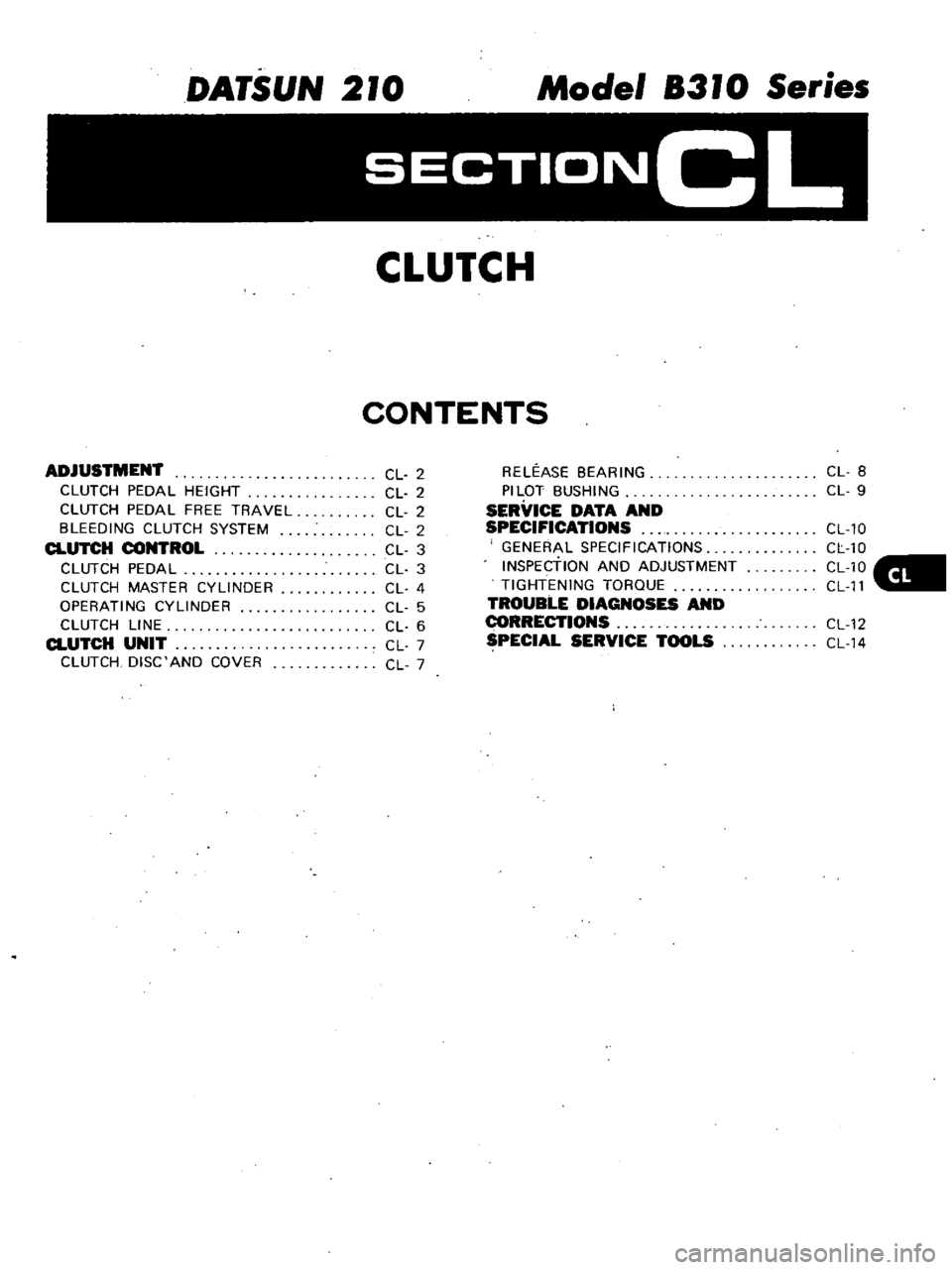
CONTENTS
ADJUSTMENT
CLUTCH
PEDAL
HEIGHT
CLUTCH
PEDAL
FREE
TRAVEL
BLEEDING
CLUTCH
SYSTEM
CLUTCH
CONTROL
CLUTCH
PEDAL
CLUTCH
MASTER
CYLINDER
OPERATING
CYLINDER
CLUTCH
LINE
CLUTCH
UNIT
CLUTCH
DISC
AND
COVER
CL
2
CL
2
CL
2
CL
2
CL
3
CL
3
CL
4
CL
5
CL
6
CL
7
CL
7
RELEASE
BEARING
PILOT
BUSHING
SERVICE
DATA
AND
SPECIFICATIONS
GENERAL
SPECIFICATIONS
INSPEctiON
AND
ADJUSTMENT
TIGHTENING
TORQUE
TROUBLE
DIAGNOSES
AND
I
ECTIONS
SPECIAL
SERVICE
TOOLS
CL
8
CL
9
CL
10
CL
10
CL10
CL
11
CL
12
CL
14
Page 204 of 548
CLUTCH
PEDAL
HEIGHT
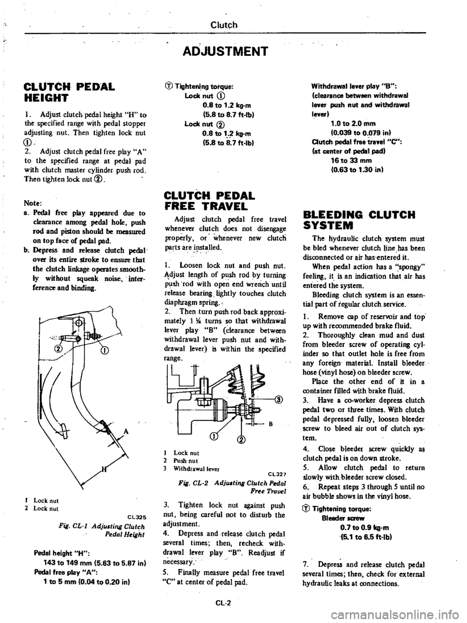
I
Adjust
clutch
pedal
height
H
to
the
specified
range
with
pedal
stopper
adjusting
nut
Then
tighten
lock
nut
CD
2
Adjust
clutch
pedal
free
play
A
to
the
specified
range
at
pedal
pad
with
clutch
master
cylinder
push
rod
Then
tighten
lock
nut
@
Note
a
Pedal
free
play
appeared
due
to
clearance
among
pedal
hole
push
rod
and
piston
should
be
measured
on
top
face
of
pedal
pad
b
Depress
and
release
clutch
pedal
over
its
entire
stroke
to
ensure
that
the
clutch
linkage
operates
smooth
ly
without
squeak
noise
inter
ference
and
binding
I
I
Lock
nut
2
Lock
nut
Cl325
Fig
CL
I
AdjlUting
Clutch
Pedal
Height
Pedal
height
H
143
to
149
mm
5
63
to
5
87
in
Pedal
free
play
An
1
to
5
mm
0
04
to
0
20
in
Clutch
ADJUSTMENT
tfl
Tightening
torque
Lock
nut
CD
0
8
to
1
2
kg
m
5
8
to
8
7
ft
Ib
Lock
nut
@
0
8
to
1
Icll
m
5
8
to
8
7
ft
lbl
CLUTCH
PEDAL
FREE
TRAVEL
Adjust
clutch
pedal
free
travel
whenever
clutch
does
not
disengage
properly
or
whenever
new
clutch
parts
are
i
lslalled
I
Loosen
lock
nut
and
push
nut
djust
length
of
push
rod
by
turning
p
lsh
rod
with
open
end
wrench
until
release
bearing
lightly
touches
clutch
dia
phragm
spring
2
Then
turn
push
rod
back
approxi
mately
I
4
turns
so
that
withdrawal
lever
play
B
clearance
between
withdrawal
lever
push
nut
and
with
drawal
lever
is
within
the
specified
range
V
@
1
B
I
Lock
nut
2
Push
nut
3
Withdrawallcver
CL327
Fig
CL
2
AdjlUting
Clutch
Pedal
Free
Trauel
3
Tighten
lock
nut
against
push
nut
being
careful
not
to
disturb
the
adjustment
4
Depress
and
release
clutch
pedal
several
times
then
recheck
with
drawal
lever
play
B
Readjust
if
necessary
5
Finally
measure
pedal
free
travel
C
at
center
of
pedal
pad
CL
2
Withdrawalle
er
play
nBn
clearance
between
withdrawal
I
er
push
nut
and
withdrawal
le
erl
1
0
to
2
0
mm
0
039
to
0
079
in
Clutch
pedal
free
tr
el
en
at
center
of
pedal
pad
16to33
mm
0
63
to
1
30
in
BLEEDING
CLUTCH
SYSTEM
The
hydraulic
clutch
system
must
be
bled
whenever
clutch
line
has
been
disconnected
or
air
has
entered
it
When
pedal
action
has
a
spongy
feeling
it
is
an
indication
that
air
has
entered
the
system
Bleeding
clutch
system
is
an
essen
tial
part
of
regular
clutch
service
I
Remove
cap
of
reservoir
and
top
up
with
recommended
brake
fluid
2
Thoroughly
clean
mud
and
dust
from
bleeder
screw
of
operating
cyl
inder
so
that
outlet
hole
is
free
from
any
foreign
material
Install
bleeder
hose
vinyl
hose
on
bleeder
screw
Place
the
other
end
of
it
in
a
container
filled
with
brake
fluid
3
Have
a
co
worker
depress
clutch
pedal
two
or
three
times
With
clutch
pedal
depressed
fully
loosen
bleeder
screw
to
bleed
air
out
of
clutch
sys
tem
4
Close
bleeder
screw
quickly
as
clutch
pedal
is
on
down
stroke
5
Allow
clutch
pedal
to
return
slowly
with
bleeder
screw
closed
6
Repeat
steps
3
through
5
until
no
air
bubble
shows
in
the
vinyl
hose
tfl
Tightening
torque
Bleeder
screw
0
7
to
0
9
kg
m
5
1
to
6
5
ft
lbl
7
Depress
and
release
clutch
pedal
several
times
then
check
for
external
hydraulic
leaks
at
connections
Page 205 of 548
Note
a
Brake
fluid
conlaining
air
is
white
and
has
visible
air
bubbles
b
Brake
fluid
containing
no
air
runs
out
of
bleeder
screw
in
a
1lO6d
stream
without
air
bubbles
c
Pay
close
attention
to
clutch
fluid
level
in
reservoir
during
bleeding
operation
Clutch
d
Pour
brake
fluid
into
reServoir
up
to
the
specified
level
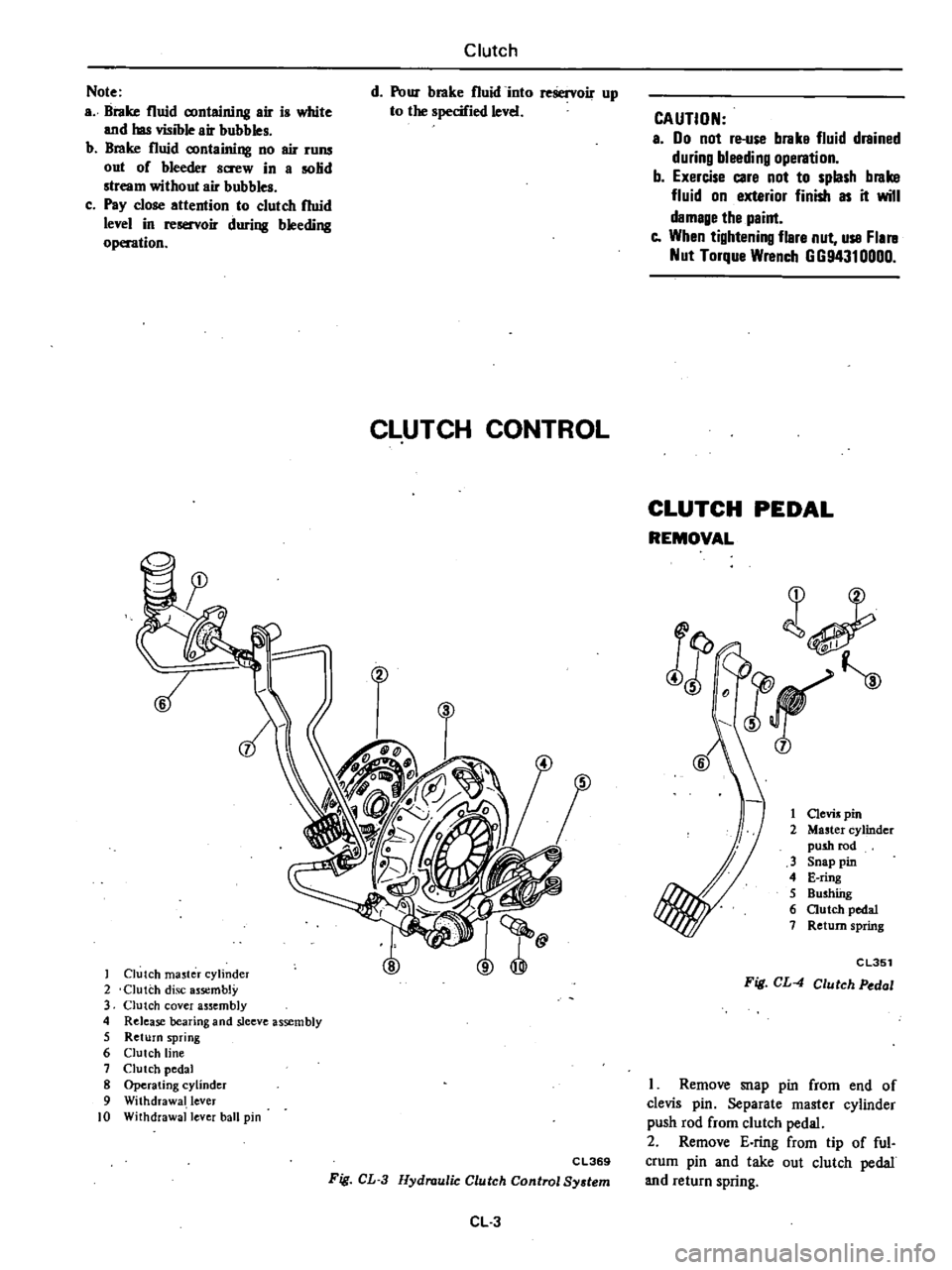
CLUTCH
CONTROL
Clutch
ma5ter
cylinder
2
Clutch
disc
assembly
3
Clutch
cover
assembly
4
Release
bearing
and
sleeve
assembly
5
Return
spring
6
Clutch
line
7
Clutch
pedal
8
Operating
cylinder
9
Withdrawal
lever
10
Withdrawal
lever
ball
pin
CAUTION
a
00
not
re
use
brake
fluid
drained
during
bleeding
operation
b
Exercise
care
not
to
splash
brake
fluid
on
exterior
finish
as
it
will
damage
the
paint
e
When
tightening
flare
nut
use
Flal
ll
Nut
Torque
Wrench
GG94310000
CLUTCH
PEDAL
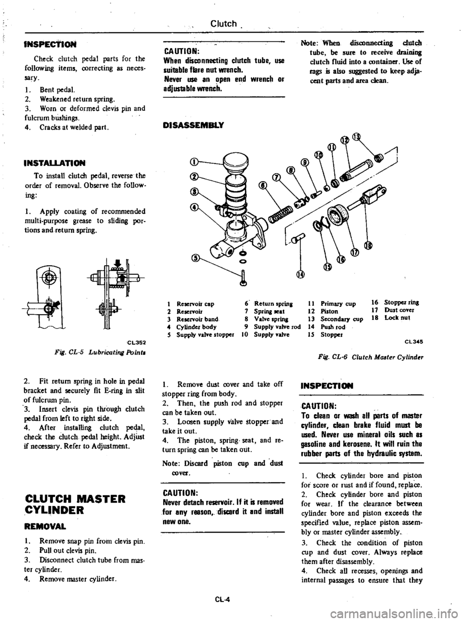
REMOVAL
l
JF
j
1
Clevis
pin
2
Master
cylinder
push
rod
3
Snap
pin
4
E
ring
5
Bushfug
6
autch
pedal
7
Return
spring
j
CL351
Fig
CL
4
Clutch
Pedal
C
L369
Fig
CL
3
Hydraulic
Clutch
Control
System
CL
3
I
Remove
snap
pin
from
end
of
clevis
pin
Separate
master
cylinder
push
rod
from
clutch
pedal
2
Remove
E
ring
from
tip
of
ful
crum
pin
and
take
out
clutch
pedal
and
return
spring
Page 206 of 548
INSPEctiON
Check
clutch
pedal
parts
for
the
following
items
correcting
neces
sary
I
Bent
pedal
2
Weakened
return
spring
3
Worn
or
deformed
clevis
pin
and
fulcrum
bwhings
4
Cracks
at
welded
part
INSTAl1
ATION
To
install
clutch
pedal
reverse
the
order
of
removal
Observe
the
follow
ing
I
Apply
coating
of
recommended
multi
purpose
grease
to
sliding
por
tions
and
return
spring
Lt
of
I
ii
CL352
Fig
CL
5
Lubricating
Point
2
Fit
return
spring
in
hole
in
pedal
bracket
and
securely
fit
E
ring
in
slit
of
fulcrum
pin
3
Insert
clevis
pin
through
clutch
pedal
from
left
to
right
side
4
After
installing
clutch
pedal
check
the
clutch
pedal
height
AdjUst
if
necessary
Refer
to
Adjwtment
CLUTCH
MASTER
CYLINDER
REMOVAL
I
Remove
snap
pin
from
clevis
pin
2
Pull
out
clevis
pin
3
Disconnect
clutch
tube
from
mas
ter
cylinder
4
Remove
master
cylinder
Clutch
CAUTION
When
disconnecting
clutch
tube
use
suitable
flare
nut
wrench
Never
use
an
open
end
wrench
or
adjus1able
wrench
DISASSEMBLY
Note
When
disconnecting
dutch
tube
be
sure
to
receive
draioillll
clutch
fluid
into
a
container
Use
of
rags
is
also
suggested
to
keep
adja
cent
parts
and
area
clean
@
@
1
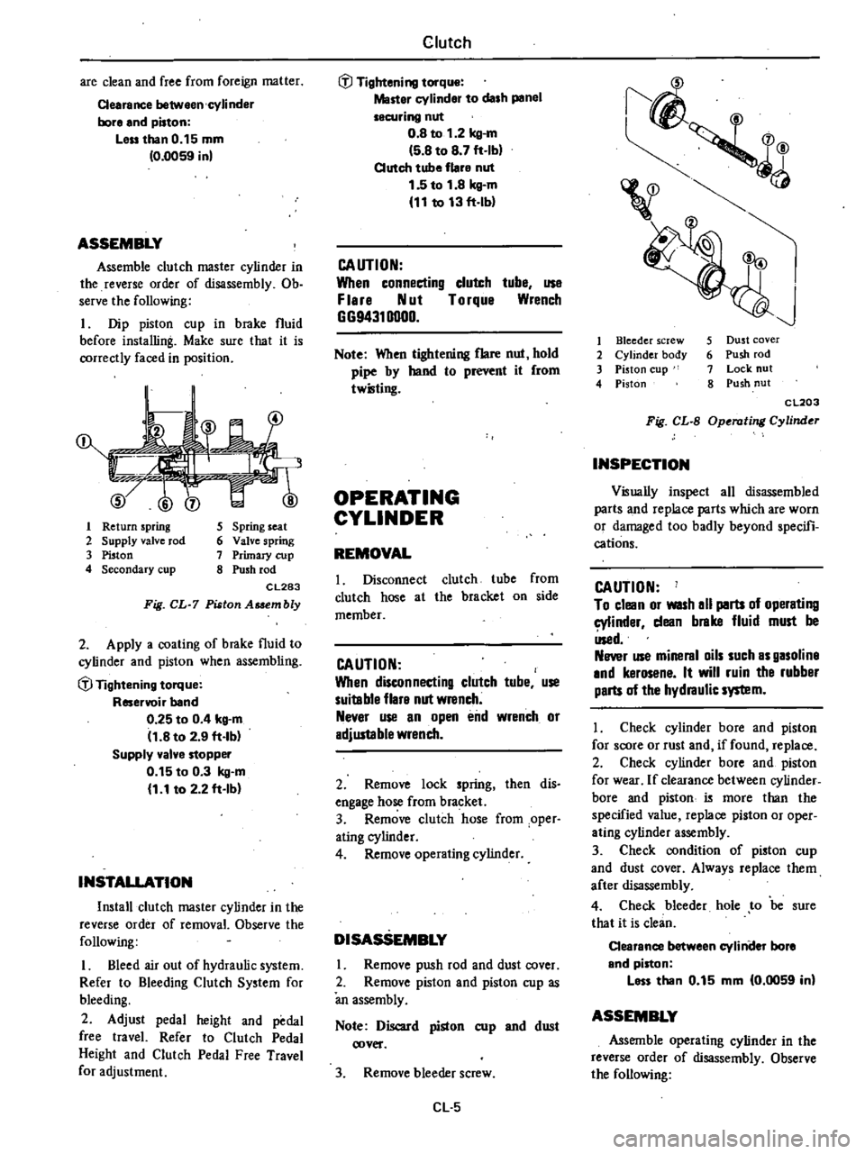
Reservoir
cap
6
Return
prina
11
Primary
cup
16
StOppel
rins
2
Reservoir
7
Sprina
seat
12
Piston
17
Dust
cover
3
Rescrvou
band
8
Valve
sprina
3
Secondary
cup
18
Lock
nut
4
Cylinder
body
9
Supply
valve
rod
14
Push
rod
5
Supply
yalYe
stopper
10
Supply
valve
15
Stopper
CL345
Fig
CL
6
Clutch
Mcuter
Cylind
r
I
Remove
dwt
cover
and
take
off
stopper
ring
from
body
2
Then
the
push
rod
and
stopper
can
be
taken
out
3
Loosen
supply
valve
stopper
and
take
it
out
4
The
piston
spring
seat
and
reo
turn
spring
can
be
taken
out
Note
Discard
piston
cup
and
dust
cover
CAUTION
Never
detach
reservoir
If
it
is
removed
for
any
reason
discard
it
and
instill
new
one
CL
4
INSPECTION
CAUTION
To
clean
or
wash
all
parts
of
masler
cylinder
clean
brake
fluid
must
be
used
Never
use
mineral
oils
such
as
gasoline
and
kerosene
It
will
ruin
tha
rubber
parts
of
tha
hydraulic
syslBm
I
Check
cylinder
bore
and
piston
for
score
or
rust
and
if
found
replace
2
Check
cylinder
bore
and
piston
for
wear
If
the
clearance
between
cylinder
bore
and
piston
exceeds
the
specified
value
replace
piston
assem
bly
or
master
cylinder
assembly
3
Check
the
condition
of
piston
cup
and
dust
cover
Always
replace
them
after
disassembly
4
Check
all
recesses
openings
and
internal
passages
to
ensure
that
they
Page 207 of 548
are
clean
and
free
from
foreign
matter
Cearance
between
cylinder
bore
and
piston
Leu
than
0
15
mm
0
0059
in
ASSEMBLY
Assemble
clutch
master
cylinder
in
the
reverse
order
of
disassembly
Ob
serve
the
following
I
Dip
piston
cup
in
brake
fluid
before
installing
Make
sure
that
it
is
correctly
faced
in
position
1
Return
spring
2
Supply
valve
rod
3
Piston
4
Secondary
cup
5
Spring
seat
6
Valve
spring
7
Primary
cup
8
Push
rod
CL283
Fig
CL
7
Piston
Asaembly
2
Apply
a
coating
of
brake
fluid
to
cylinder
and
piston
when
assembling
if
Tightening
torque
Reservoir
band
0
25
to
0
4
kg
m
11
8
to
2
9
ft
lb
Supply
valve
stopper
0
15
to
0
3
kg
m
1
1
to
2
2
ft
Ib
INSTALLATION
Install
clutch
master
cylinder
in
the
reverse
order
of
removal
Observe
the
following
I
Bleed
air
out
of
hydraulic
system
Refer
to
Bleeding
Clutch
System
for
bleeding
2
Adjust
pedal
height
and
pedal
free
travel
Refer
to
Clutch
Pedal
Height
and
Clutch
Pedal
Free
Travel
for
adjustment
Clutch
if
Tightening
torque
Master
cylinder
to
dash
panel
securing
nut
0
8
to
1
2
kg
m
5
8
to
8
7
ft
Ib
Clutch
tube
flare
nut
1
5
to
1
8
kg
m
11
to
13
ft
lb
CAUTION
When
connecting
clutch
tube
use
F
lere
Nut
Torque
Wrench
GG94310000
Note
When
tightening
flare
nut
hold
pipe
by
hand
to
r
it
from
twilling
OPERATING
CYLINDER
REMOVAL
I
Disconnect
clutch
tube
from
clutch
hose
at
the
bracket
on
side
member
CAUTION
When
disconnecting
clutch
tube
use
suitable
flare
nut
wrench
Never
use
an
open
end
wrench
or
adjustable
wrench
2
Remove
lock
spring
then
dis
engage
hose
from
bracket
3
Remove
clutch
hose
from
oper
ating
cylinder
4
Remove
operating
cylinder
DISASSEMBLY
Remove
push
rod
and
dust
cover
2
Remove
piston
and
piston
cup
as
an
assembly
Note
Discard
piston
cup
and
dust
cover
3
Remove
bleeder
screw
Cl
5
1
4
v
I
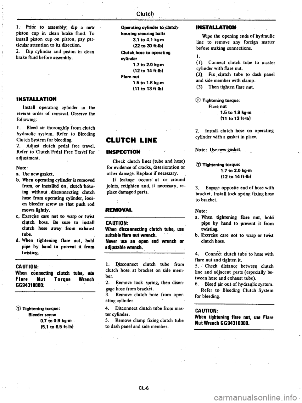
Bleeder
screw
2
Cylinder
body
3
Piston
cup
4
Piston
5
Dust
cover
6
Push
rod
7
Lock
nut
8
Push
nut
CL203
Fig
CL
B
Operating
Cylinder
INSPECTION
Visually
inspect
all
disassembled
parts
and
replace
parts
which
are
worn
or
damaged
too
badly
beyond
specifi
cations
CAUTION
To
clean
or
WISh
all
parts
of
operating
cylinder
dean
brake
fluid
must
be
Used
Never
use
mineral
oils
such
as
gasoline
and
kerosene
It
will
ruin
the
rubber
parts
of
the
hydraulic
system
I
Check
cylinder
bore
and
piston
for
score
or
rust
and
if
found
replace
2
Check
cylinder
bore
and
piston
for
wear
If
clearance
between
cylinder
bore
and
piston
i5
more
than
the
specified
value
replace
piston
or
oper
ating
cylinder
assembly
3
Check
condition
of
piston
cup
and
dust
cover
Always
replace
them
after
disassembly
4
Check
bleeder
hole
to
be
sure
that
it
is
clean
Clearance
between
cyliniler
bore
and
piston
less
than
0
15
mm
0
0059
in
ASSEMBLY
Assemble
operating
cylinder
in
the
reverse
order
of
disassembly
Observe
the
following
Page 208 of 548
t
Prior
to
lWembly
dip
a
new
piston
cup
in
clean
brake
fluid
To
install
piston
cup
on
piston
pay
par
ticular
auention
to
its
direction
2
Dip
cylinder
and
piston
in
clean
brake
fluid
before
assembly
INSTALLATION
Install
operating
cylinder
in
the
reverse
order
of
removal
Observe
the
following
1
Bleed
air
thoroughly
from
clutch
hydraulic
system
Refer
to
Bleeding
Clutch
System
for
bleeding
2
Adjust
clutch
pedal
free
travel
Refer
to
Clutch
Pedal
Free
Travel
for
adjustment
Note
a
Use
new
gasket
b
When
operating
cylinder
is
removed
from
or
instaUed
on
clutch
haus
ing
without
disconnecting
clutch
hose
from
operating
cylinder
loos
en
bleeder
screw
so
that
push
rod
mo
lightly
c
E
xer
e
care
not
to
p
or
wist
clutch
hose
Be
sure
to
install
clutch
hose
away
from
exhaust
tube
d
When
tightening
flare
nut
hold
pipe
by
hand
to
prevent
it
from
twisting
CAUTION
When
connecting
dutch
tuhe
uSe
Flare
Nut
Torque
Wrench
G694310000
@
Tightening
torque
Bleeder
screw
0
7
to
0
9
kg
m
5
1
to
6
5
ft
Ihl
Clutch
o
cylinder
to
clutch
housing
securing
bolts
3
1
to
4
1
kg
m
22
to
30
ft
lbl
Clutch
hose
to
operating
cyli
nder
1
7
to
2
0
kg
m
12
to
14
ft
lbl
Flare
nut
1
5
to
1
8
kg
m
11
to
13
ft
Ibl
CLUTCH
LINE
INSPECTION
Check
clutch
lines
tube
and
hose
for
evidence
of
cracks
deterioration
or
other
damage
Replace
if
necessary
If
leakage
occurs
at
or
around
joints
retighten
and
if
necessary
re
place
damaged
parts
REMOVAL
CAUTION
When
disconnecting
clutch
tube
use
suitable
flare
nut
wrench
Never
use
an
open
end
wrench
or
adjustable
wrench
1
Qisconnect
clutch
tube
from
clutch
hose
at
bracket
on
side
mem
ber
2
emove
lock
spring
then
disen
gage
hose
from
bracket
3
Remove
clutch
hose
from
oper
ating
cylinder
4
Disconnect
clutch
tube
from
mas
ter
cylinder
5
Remove
clamp
fIxing
clutch
tube
to
dash
panel
and
side
member
CL
6
INSTALLAnOlll
Wipe
the
opening
ends
of
hydraulic
line
to
remove
any
foreign
matter
before
malting
connections
I
Connect
clutch
tuhe
to
master
cylinder
with
flare
nut
2
Fix
clutch
tube
to
dash
panel
and
side
member
with
clamp
3
Then
tighten
flare
nut
@
Tightening
torque
Flar
nut
1
5
to
1
8
kg
m
11
to
13
ft
Ibl
2
InstaU
clutch
hose
on
operating
cylinder
with
a
gasket
in
place
Note
Use
new
gaslcet
@
Tightening
torque
1
7
to
2
0
kg
m
12
to
14ft
lbl
3
Engage
opposite
end
of
hose
with
bracket
InstaU
lock
spring
fIxing
hose
to
bracket
Note
a
When
tightening
flare
nut
hold
pipe
by
hand
to
prevent
it
from
twisting
b
Exercise
care
not
to
warp
or
twist
clu1ch
hose
4
Connect
clutch
tube
to
hose
with
flare
nut
and
tighten
it
5
Check
distance
between
clutch
line
and
adjacent
parts
especially
be
tween
hose
and
exhaust
tube
6
Bleed
air
out
of
hydraulic
system
Refer
to
Bleeding
Clutch
System
for
bleeding
CAUTION
When
tightening
flare
nut
use
Flare
Nut
Wrench
G
G9431
0000
Page 209 of 548
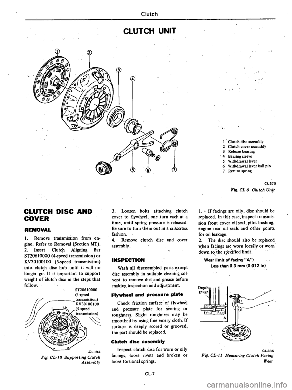
CLUTCH
DISC
AND
COVER
REMOVAL
1
Remove
transmission
from
en
gine
Refer
to
Removal
Section
MT
2
Insert
Clutch
Aligning
Bar
ST20610000
4
speed
tranSmission
or
KV30100IOO
5
speed
transmission
into
clutch
disc
hub
until
it
will
no
longer
gd
It
is
important
to
support
weight
of
clutch
disc
in
the
steps
that
follow
ST20610000
4
peed
transmission
KV30100100
S
peed
transmission
S
cL194
Fig
CL
W
Supporting
Clutch
Assembly
Clutch
CLUTCH
UNIT
n
j
3
Loosen
bolts
attaching
clutch
cover
to
flywheel
one
turn
each
at
a
time
until
spring
pressure
is
released
Be
sure
to
turn
them
out
in
a
crisscross
fashion
4
Remove
clutch
disc
and
cover
assembly
INSPECTION
Wash
all
disassembled
parts
except
disc
assembly
in
suiiable
cleaning
sol
vent
to
remove
dirt
and
grease
before
making
inspection
and
adjustment
FI
1
and
pressure
plate
Check
friction
surface
of
flywheel
and
pressure
plate
for
scoring
or
roughness
Slight
roughness
may
be
smoothed
by
using
fine
emery
cloth
If
surface
is
deeply
scored
or
grooved
the
part
should
be
replaced
Clutch
disc
sembi
Inspect
clutch
disc
for
worn
or
oily
facings
loose
rivets
and
broken
or
loose
torsional
springs
CL
7
1
Clutch
disc
assembly
2
Clutch
cover
assembly
3
ReleaJe
bearing
4
Bearing
sleeve
S
Withdrawal
lever
6
Withdrawa11ever
ball
pin
7
Return
spring
CL370
Fig
CL
9
Clutch
Unit
I
If
facings
are
oily
disc
should
be
replaced
In
this
case
inspect
transmis
sion
front
cover
oil
seal
pilot
bushing
engine
rear
oil
seals
and
other
points
for
oil
leakage
2
The
disc
should
also
be
replaced
when
facings
are
worn
locally
or
worn
down
io
ihe
specified
limit
Wear
limit
of
facing
A
Les
than
0
3
mm
0
012
in
9111
I
A
M
m
C
L336
Fig
CL
ll
M
asur
ng
Clutch
Facing
Wear
Page 210 of 548
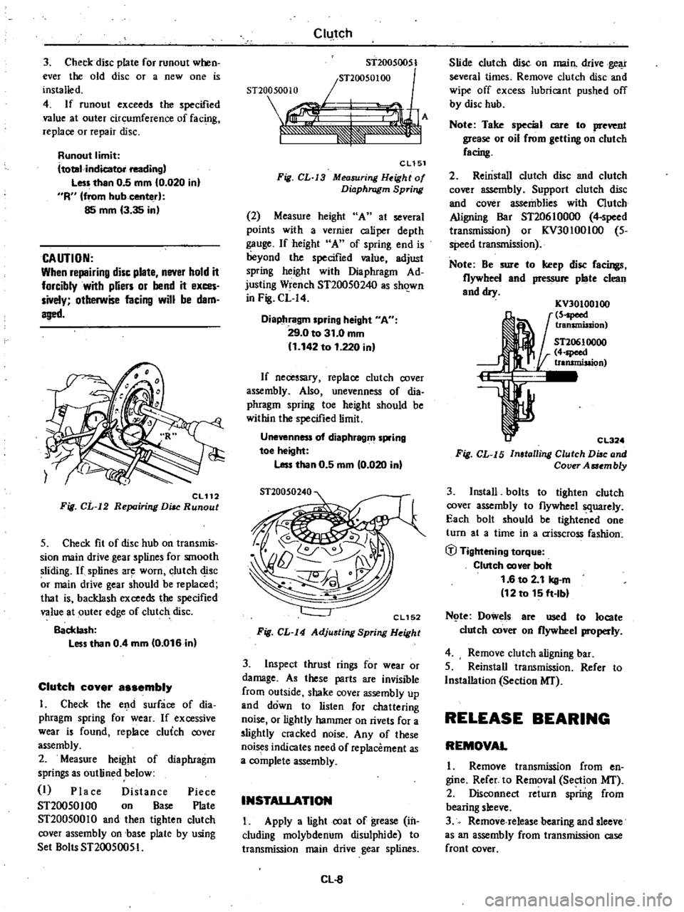
3
Check
disc
plate
for
runout
when
ever
the
old
disc
or
a
new
one
is
installed
4
If
runout
exceeds
the
specified
value
at
outer
circumference
of
fac
g
replace
or
repair
disc
Runout
limit
ltotal
indicator
reading
Less
than
0
5
mm
0
020
in
R
from
hub
center
85
mm
3
35
in
CAUTION
When
repairing
disc
plate
never
hold
it
forcibly
with
pUers
or
bend
it
exces
sively
otherwise
facing
will
be
dam
aged
CL112
Fig
CL
12
Repairing
DiM
Runout
5
Check
fit
of
disc
hub
on
transmis
sion
main
drive
gear
splines
for
smooth
sliding
If
splines
are
worn
clutch
disc
r
main
drive
gear
should
be
replaced
that
is
backlash
exceeds
the
specified
value
at
outer
edge
of
clutch
disc
Backlash
Less
than
0
4
mm
0
016
in
Clutch
cover
a
embly
I
Check
the
end
surface
of
dia
phragm
spring
for
wear
If
excessive
wear
is
found
replace
cluich
cover
assembly
2
Measure
height
of
diaphragm
springs
as
outlined
below
I
Place
Distance
Piece
ST20050100
on
Base
Plate
ST20050010
and
then
tighten
clutch
cover
assembly
on
base
plate
by
using
Set
Bolts
ST20050051
Clutch
ST200S0051
snOO50100
snoo
500
10
re1
F
A
J
eLlSl
Fig
CL
J3
Measuring
H
ight
of
Diaphragm
Spring
2
Measure
height
A
at
several
points
with
a
vernier
caliper
depth
gauge
If
height
A
of
spring
end
is
beyond
the
specified
value
adjust
spring
height
with
Diaphragm
Ad
justing
Wrench
ST20050240
as
sh
1wn
in
Fig
CL
I4
Diaphragm
spring
height
A
29
0
to
31
0
mm
1
142
to
1
220
in
If
necessary
replace
clutch
cover
assembly
Also
unevenness
of
dia
phragm
spring
toe
height
should
be
within
the
specified
limit
Unevenness
of
diaphragm
spring
toe
height
Less
than
0
5
mm
0
020
in
CL152
Fig
CL
I4
Adjusting
Spring
Height
3
Inspect
thrust
rings
for
wear
or
damage
As
these
parts
are
invisible
from
outside
shake
cover
assembly
up
and
down
to
listen
for
chattering
noise
or
lightly
hammer
on
rivets
for
a
slightly
cracked
noise
Any
of
these
noi
s
indicates
need
of
replacement
as
a
complete
assembly
INSTALlATION
I
Apply
a
light
coat
of
grease
in
cluding
molybdenum
disulphide
to
transmission
main
drive
gear
splines
Cl
8
Slide
clutch
disc
on
main
drive
gear
several
times
Remove
clutch
disc
and
wipe
off
excess
lubricant
pushed
off
by
disc
hub
Note
Take
special
care
to
prevent
grease
or
oil
rrom
getting
on
clutch
racing
2
Reinstall
clutch
disc
and
clutch
cover
assembly
Support
clutch
disc
and
cover
assemblies
with
Clutch
Aligning
Bar
ST20610000
4
speed
transmission
or
KV30100IOO
5
speed
transmission
Note
Be
sure
to
keep
disc
racings
flywheel
and
pressure
plate
clean
and
dry
KV30100100
5
peed
transmission
ST20610000
4
speed
trammisaion
CL32
Fig
CL
I5
Installing
Clutch
Diac
and
Cover
Aaembly
3
Install
bolts
to
tighten
clutch
cover
assembly
to
flywheel
squarely
Each
bolt
should
be
tightened
one
turn
at
a
time
in
a
crisscross
fashion
ifJ
Tightening
torque
Clutch
cover
bolt
1
6
to
2
1
kg
m
12
to
15
ft
Ibl
N
te
Dowels
are
used
to
locate
clutch
cover
on
flywheel
properly
4
Remove
clutch
aligning
bar
5
Reinstall
transmission
Refer
to
Installation
Section
MI
RELEASE
BEARING
REMOVAL
1
Remove
transmission
from
en
gine
Refer
to
Removal
Section
MI
2
Disconnect
return
spring
from
bearing
sleeve
3
Remove
release
bearing
and
sleeve
as
an
assembly
from
transmission
case
front
cover