GEELY CK 2008 Owners Manual
Manufacturer: GEELY, Model Year: 2008, Model line: CK, Model: GEELY CK 2008Pages: 392, PDF Size: 38.86 MB
Page 91 of 392
843. Output Level
ECU output level is designed to send control signal to the actuators of the electronic control system based on
the orders of the microprocessor in the micro-controller. The microprocessor control the output level by
controlling the occurrence position of the pulse, its length and duty ratio.
(1) Injection output level
The microprocessor controls the pulse length of the injection output level by making sure whether to
trigger to circuit or not in the injection output level.
(2) Ignition input level
The ignition output level is designed to amplify the ignition signal from the microprocessor into the primary
current of the ignition coil.
(3) Electric fuel pump output level
ECU microcontroller control the pump relay through electric fuel pump output level, and then control the
on and off of the electric fuel pump based on the current operating conditions.
(4) Other output levels
Control the output levels of the idle control valve, carbon canister solenoid valve, malfunction indicator
lamp. MR479Q, MR479QA, MR481QA engine idle control are closed loop control system, their injection
and ignition control are also closed loop control system.
Page 92 of 392

85Part II ChassisChapter 1 Transmission Control DeviceSection 1 Transmission Control DeviceDescription on Transmission Control DeviceThis model is equipped with lever and cable transmission control devices, respectively used for 1.3L and 1.5L
engine, both of their gears are: 5 forward gears + 1 reverse gear.PROBLEM SYMPTOMS TABLEUse the table below to help you find the cause of the problem. The numbers indicate the priority of the likely
cause of the problem. Check each part in order. If necessary, replace these parts.Section 2 Lever Type Transmission Control DeviceComponentsSymptom
1. Tra nsmission c ontrol de vic e se le ctor (position
changing) cable (improperly assembled)
2. Ca ble or rela te d pa rts worn
3. Ca ble a sse mbly (incorrec t)
4. T r a ns mis s ion ( f a ult y)
1. Transmission control device selector (position
changing ) cable (improperly assembled)
2. Ca ble or rela te d pa rts worn
3. Ca ble a sse mbly (incorrec t)
4. Transmission (faulty) Transmission out of gea r
Transmission shift difficultControl lever Assembly
Dust Proof Cover
Botton Panel
Assembly of body
Dust Proof Cover Retainer
Control Pull Rod AssemblySuspected Area
Page 93 of 392
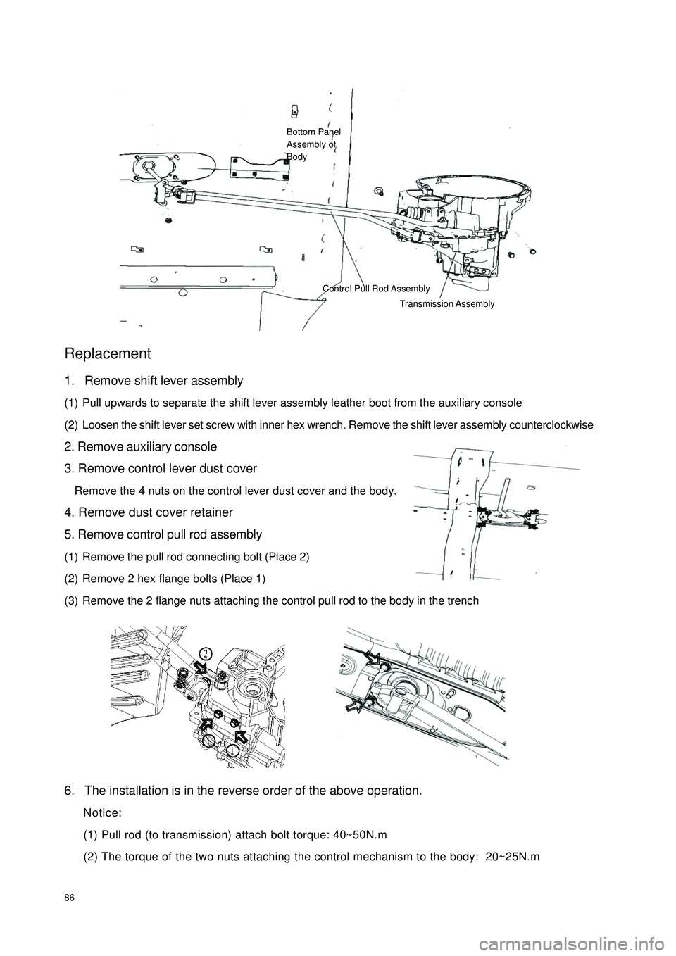
86Replacement1. Remove shift lever assembly
(1) Pull upwards to separate the shift lever assembly leather boot from the auxiliary console
(2) Loosen the shift lever set screw with inner hex wrench. Remove the shift lever assembly counterclockwise
2. Remove auxiliary console
3. Remove control lever dust cover
Remove the 4 nuts on the control lever dust cover and the body.
4. Remove dust cover retainer
5. Remove control pull rod assembly
(1) Remove the pull rod connecting bolt (Place 2)
(2) Remove 2 hex flange bolts (Place 1)
(3) Remove the 2 flange nuts attaching the control pull rod to the body in the trench
6. The installation is in the reverse order of the above operation.
Notice:
(1) Pull rod (to transmission) attach bolt torque: 40~50N.m
(2) The torque of the two nuts attaching the control mechanism to the body: 20~25N.mBottom Panel
Assembly of
BodyControl Pull Rod Assembly
Transmission Assembly
Page 94 of 392
87(3) Dust cover retainer shall be assembled well, otherwise the dust seal effect will be af-
fected
(4) Dust cover fixing nut torque: 20~25N.m
(5) Make sure the shift number words on the top of shift lever ball face towards the driving
direction of the vehicle, properly tighten the set screw of the shift lever
(6) Check whether the shift control is flexible and reliable; the shift lever shall be vertical
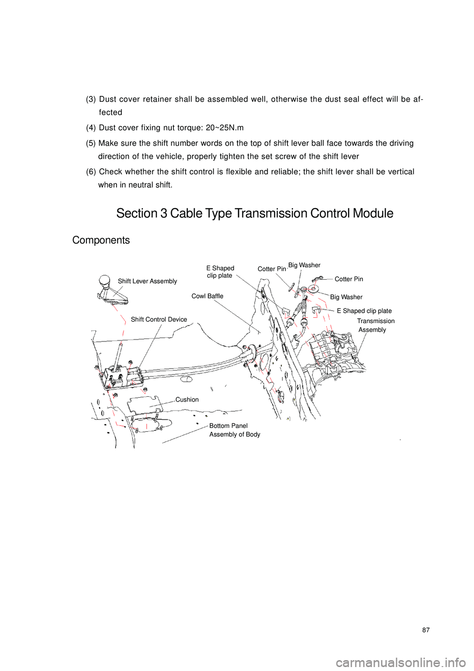
when in neutral shift.Section 3 Cable Type Transmission Control ModuleComponentsShift Lever AssemblyE Shaped
clip plateCotter PinBig Washer Big Washer Cotter PinE Shaped clip plateTransmission
AssemblyCowl BaffleShift Control DeviceCushionBottom Panel
Assembly of Body
Page 95 of 392
88Replacement1. Remove shift lever assembly
(1) Pull upwards to separate shift lever assembly leather boot from the auxiliary console
(2) Loosen shift lever set screw with inner hex wrench. Remove the shift lever assembly counterclockwise.
2. Remove the auxiliary console
3. Remove the 4 nuts connecting manual shift assembly and the floor
4. Remove the shift cushion
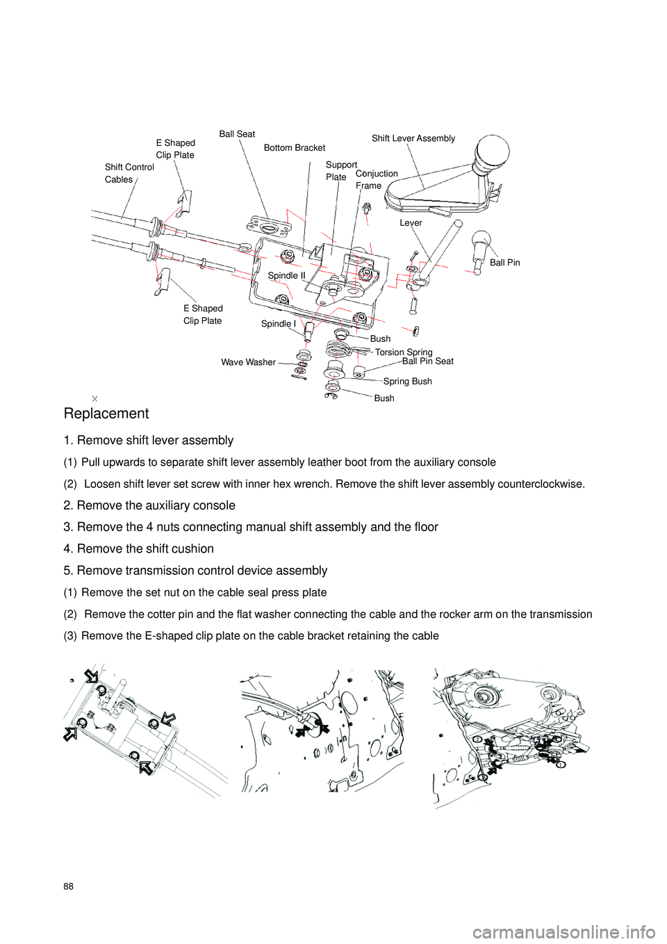
5. Remove transmission control device assembly
(1) Remove the set nut on the cable seal press plate
(2) Remove the cotter pin and the flat washer connecting the cable and the rocker arm on the transmission
(3) Remove the E-shaped clip plate on the cable bracket retaining the cableShift Control
CablesE Shaped
Clip PlateBall SeatShift Lever Assembly LeverBall PinSpindle IISpindle IE Shaped
Clip PlateWave WasherBushBushSpring BushBall Pin Seat Torsion Spring Support
Plate Bottom BracketConjuction
Frame
Page 96 of 392
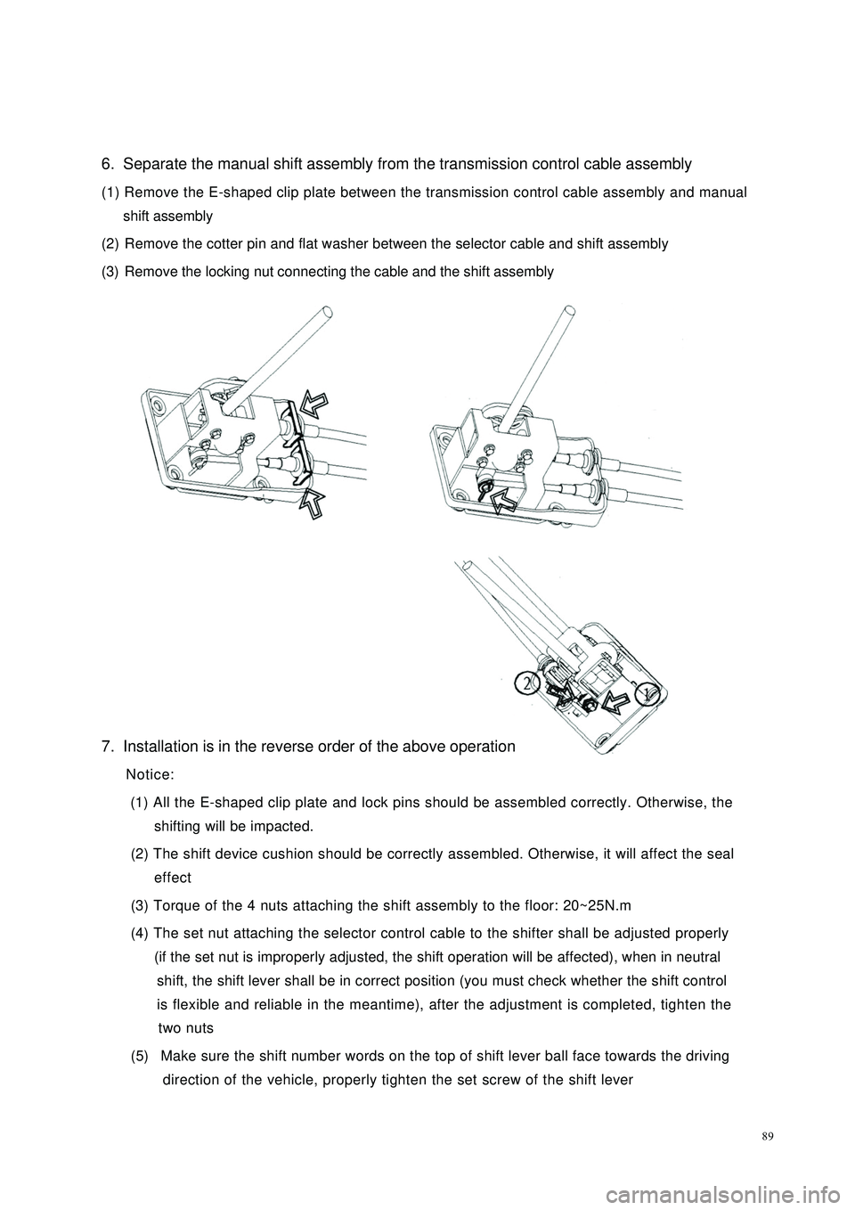
896. Separate the manual shift assembly from the transmission control cable assembly
(1) Remove the E-shaped clip plate between the transmission control cable assembly and manual
shift assembly
(2) Remove the cotter pin and flat washer between the selector cable and shift assembly
(3) Remove the locking nut connecting the cable and the shift assembly
7. Installation is in the reverse order of the above operation
Notice:
(1) All the E-shaped clip plate and lock pins should be assembled correctly. Otherwise, the
shifting will be impacted.
(2) The shift device cushion should be correctly assembled. Otherwise, it will affect the seal
effect
(3) Torque of the 4 nuts attaching the shift assembly to the floor: 20~25N.m
(4) The set nut attaching the selector control cable to the shifter shall be adjusted properly
(if the set nut is improperly adjusted, the shift operation will be affected), when in neutral
shift, the shift lever shall be in correct position (you must check whether the shift control
is flexible and reliable in the meantime), after the adjustment is completed, tighten the
two nuts
(5) Make sure the shift number words on the top of shift lever ball face towards the driving
direction of the vehicle, properly tighten the set screw of the shift lever
Page 97 of 392

90Chapter 2 Accelerator PedalSection 1 Accelerator PedalComponents
Replacement1. Remove the accelerator cable
Loosen the set nut attaching the accelerator cable to the accelerator
cable bracket on the engine, remove the accelerator cable from
the throttle valve rocker arm
2. Remove accelerator pedal
(1) Remove two set nut between the accelerator pedal
and vehicle body
(2) Separate the accelerator cable
3. Detach the accelerator cable
4.Install the accelerator cable and accelerator pedal assembly in the reverse order of the
Notice:
(1) Accelerator pedal assembly fixing bolt torque: 20~25N.m
(2) Properly adjust the position of the accelerator cable set screw to ensure the adequate
tension of the accelerator cable
(3) Check whether the accelerator control is flexible and reliableCowl BaffleHole Plug
Accelerator
Pedal Assembly Accelerator CableAdjusting NutConnect
The Engineabove procedure.
Page 98 of 392

91Chapter 3 Clutch Control SystemSection 1 Clutch Control SystemClutch operating system descriptionThis model is equipped with hydraulic and cable clutch control system, respectively used for 1.3L engine
1.5L engine.PROBLEM SYMPTOMS TABLEUse the table below to help you find the cause of the problem. The numbers indicate the priority of the likely
cause of the problem. Check each part in order. If necessary, replace these parts.Section 2 Clutch Cable Control MechanismComponentsSympto m Sus pe cte d Are a
1. Clutc h pe da l position (Too low)
2. Control mec ha nism (Stagna tion)
3. Clutc h pe da l fre e stroke (too la rge)
C lut c h doe s not r e le a s e 1. H ydr a ulic pipe line ( A ir in line )
1. Control system (Incorrect assembly & adjustment)
2. Clutc h asse mbly (Fa ulty) Clutch noisyC lut c h s lipsConnect The
Clutch Fork Clutch Cable
Assmbly
Adjusting NutCowl Baffle
Clutch and Brake
Pedal Assembly
Page 99 of 392
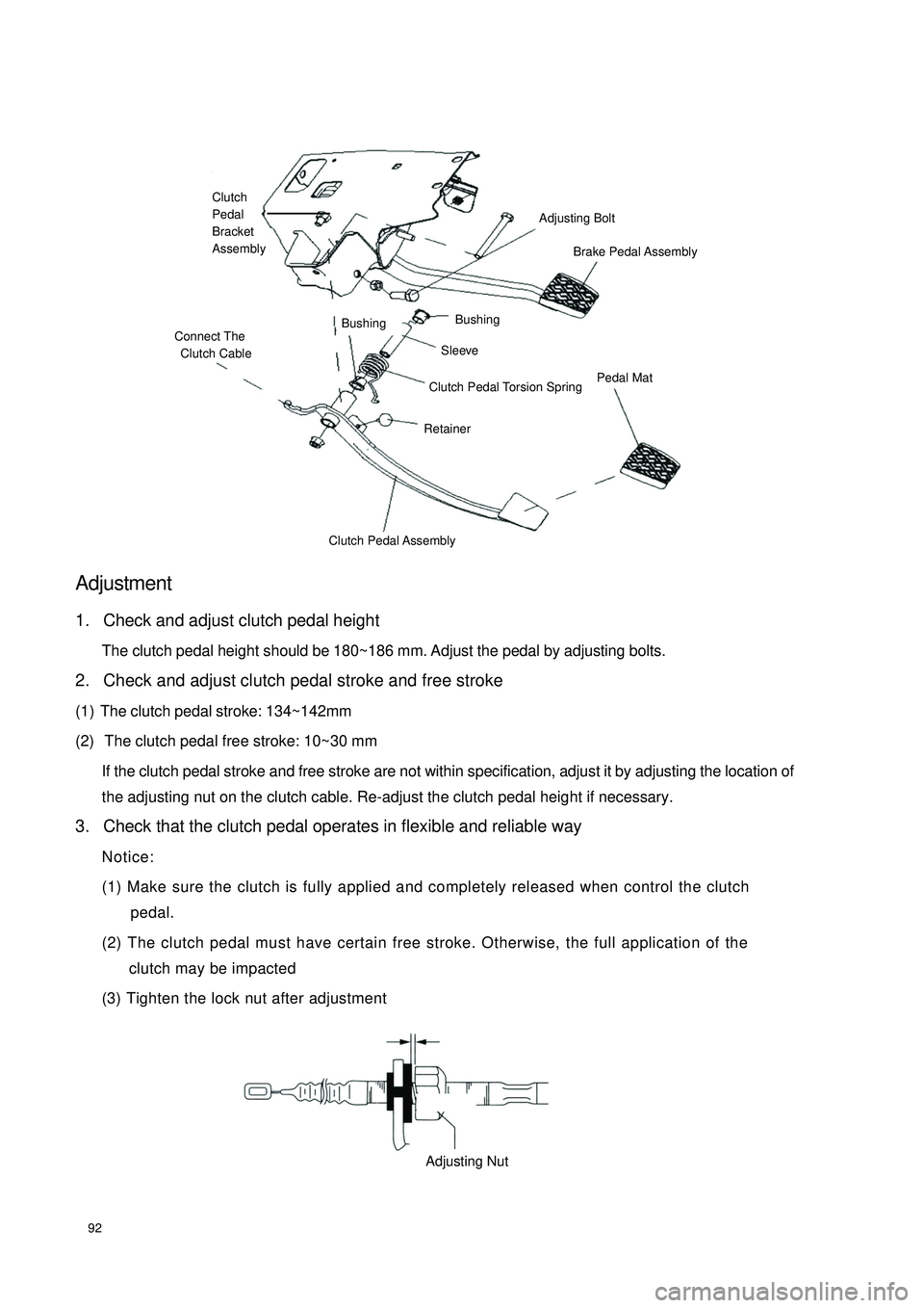
92Adjustment1. Check and adjust clutch pedal height
The clutch pedal height should be 180~186 mm. Adjust the pedal by adjusting bolts.
2. Check and adjust clutch pedal stroke and free stroke
(1) The clutch pedal stroke: 134~142mm
(2) The clutch pedal free stroke: 10~30 mm
If the clutch pedal stroke and free stroke are not within specification, adjust it by adjusting the location of
the adjusting nut on the clutch cable. Re-adjust the clutch pedal height if necessary.
3. Check that the clutch pedal operates in flexible and reliable way
Notice:
(1) Make sure the clutch is fully applied and completely released when control the clutch
pedal.
(2) The clutch pedal must have certain free stroke. Otherwise, the full application of the
clutch may be impacted
(3) Tighten the lock nut after adjustmentConnect The
Clutch CableBushingBushingAdjusting BoltBrake Pedal Assembly Sleeve Clutch Pedal Torsion Spring Retainer Pedal MatClutch Pedal AssemblyClutch
Pedal
Bracket
AssemblyAdjusting Nut
Page 100 of 392

93Replacement1. Remove the clutch cable
(1) Loosen the clutch adjusting nut. Separate the clutch cable from the accelerator rocker arm
(2) Remove the 2 set bolts from the clutch cable on the cowl panel
(3) Separate the clutch cable from the clutch pedal
2. Install the clutch cable assembly in the reverse order of the above procedure.
Notice:
(1) The clutch cable assembly on the cowl panel set bolt torque : 20~25N.m
(2) Check and adjust the pedal according to the above-mentioned requirement in
"Adjustment".Adjusting BoltStrokeFree
StrokeMinimum Distance from the Cowl Panel Adjusting Bolt
NutInstall HeightAdjusting Nut