GEELY CK 2008 Workshop Manual
Manufacturer: GEELY, Model Year: 2008,
Model line: CK,
Model: GEELY CK 2008
Pages: 392, PDF Size: 38.86 MB
GEELY CK 2008 Workshop Manual
CK 2008
GEELY
GEELY
https://www.carmanualsonline.info/img/58/57159/w960_57159-0.png
GEELY CK 2008 Workshop Manual
Trending: ignition, radiator, load capacity, alternator, differential, airbag off, oil type
Page 111 of 392

104PROBLEM SYMPTOMS TABLEUse the table below to help you find the cause of the problem. The numbers indicate the priority of the likely
cause of the problem. Check each part in order. If necessary, replace parts.Sympto m Sus pe cte d Are a
1. Tires (Worn or imprope rly infla te d)
2. Wheel alignment (Incorrect)
3. Steering system joint(Loose or worn)
4. Hub be a ring (Worn)
5. Ste e ring ge a r (Out of adjustme nt or worn)
6. Suspe nsion pa rts (Worn or da ma ge d)
1. Ve hic le (Ove rloa de d)
2. Spring (stiffne ss not comply with or da ma ge )
3. Shoc k a bsorbe r (Worn)
1. Tire (Worn or imprope rly infla te d)
2. Stee ring linka ge (Loose or dama ged)
3. Sta bilize r ba r (Be nt or broke n)
4. Shoc k a bsorbe r (Worn or da mage d)
1. Tire (Worn or imprope rly infla te d)
2. T ir e ( D yna mic ba la nc e is not a s s pe c if ie d)
3. Shock a bsorber (Worn or da ma ge d)
4. Wheel alignment (Incorrect)
5. Ball stud pin (Worn or da mage d)
6. Hub be aring (Worn or da mage d)
7. Ste ering linka ge (Loose or worn)
8. Ste e ring ge a r (Out of adjustme nt or worn)
1. Tire (Worn or imprope rly infla ted)
2. Wheel alignment (Incorrect)
3. Shoc k a bsorbe r (Worn or da mage d)
4. Suspe nsion pa rts (Worn or da ma ge d) Abnormal tire wearDeviation
Body Desc ent
Sways
F r ont w he e l s himmy
Page 112 of 392
105Section 2 Front SuspensionComponents
LF Strut Assembly
Front
Brake Hose Clip
Connected to Brake
Connected
to Brake
LF Brake Assembly
Stabilizer Bar
Left Link Rod
Assembly
Left lower Swing
Arm Assembly
Lower Swing
Arm LF Bracket
Lower Swing Arm
RF Bracket
Front Stabilizer Bar Assembly
Stabilizer Bar
Right Link Rod Assembly
RF Brake Assembly
Connected to Brake
Clip
Front Brake Hose
RF Strut Assembly
Connected
to Brake
BodyBody
Right Lower
Swing Arm
Assembly
Lower Trailing
Arm Rear Elastic Hinge
Fixed to Shock
Absorber
ABS Sensor Wire Harness
Shock Absorber
Page 113 of 392
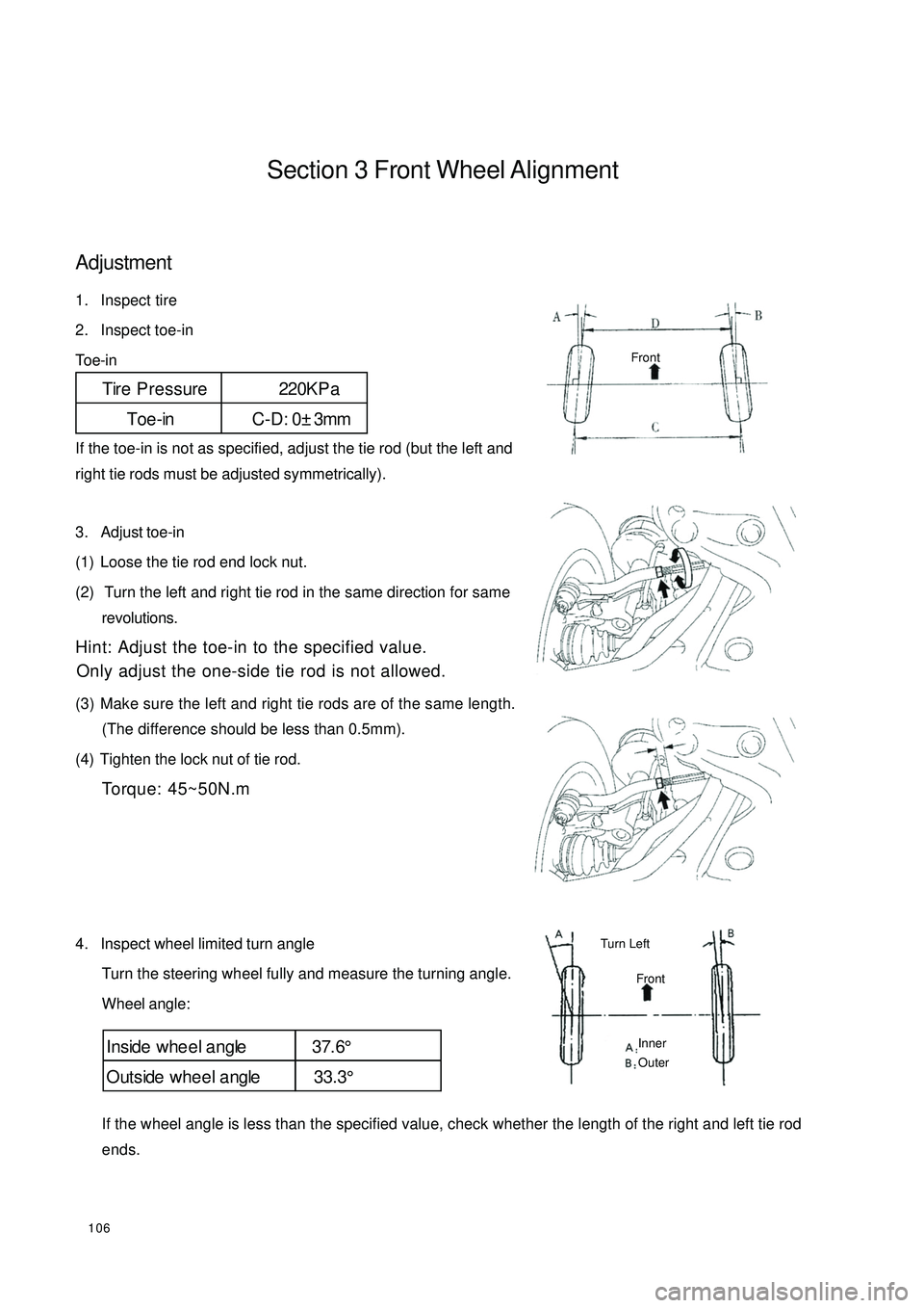
106Section 3 Front Wheel AlignmentAdjustment1. Inspect tire
2. Inspect toe-in
Toe-in
If the toe-in is not as specified, adjust the tie rod (but the left and
right tie rods must be adjusted symmetrically).
3. Adjust toe-in
(1) Loose the tie rod end lock nut.
(2) Turn the left and right tie rod in the same direction for same
revolutions.
Hint: Adjust the toe-in to the specified value.
Only adjust the one-side tie rod is not allowed.
(3) Make sure the left and right tie rods are of the same length.
(The difference should be less than 0.5mm).
(4) Tighten the lock nut of tie rod.
Torque: 45~50N.m
4. Inspect wheel limited turn angle
Turn the steering wheel fully and measure the turning angle.
Wheel angle:
If the wheel angle is less than the specified value, check whether the length of the right and left tie rod
ends.Tire Pressure 220KP a
Toe-in C-D: 0±3mmInside whe e l a ngle 37.6°
Outside whee l a ngle 33.3°FrontFrontTurn Left Inner
Outer
Page 114 of 392
107Section 4 Front Strut AssemblyComponents:WasherMount CoverShock Absorber Mount SupportBig WasherThrust Ball BearingSpring Upper SeatFront Coil Spring
Upper InsulatorFront Coil SpringLeft Brake Assembly ABS Sensor Wire HarnessFront Brake Hose Stabilizer Bar Left
Link Rod AssemblyLF Shock Absorber AssemblyFront Coil Spring Lower InsulatorFront BumperFront Shock Absorber
Protecting Sleeve
Page 115 of 392
108Replacement1. Remove the front wheel.
2. Remove the ABS sensor from the steering knuckle. Separate the sensor and signal wire from the wire
harness bracket on the front shock absorber.
3. Separate the front brake hose
Remove 2 clips and separate the front brake hose from the front shock absorber bracket.
4. Remove the stabilizer bar link rod assembly
Remove the nut connecting the stabilizer bar link rod assembly and the shock absorber.
5. Remove the front shock absorber with the coil spring
(1) Remove the nuts and bolts connecting the shock absorber and brake.
(2) Remove the 4 nuts connecting the front shock absorber and vehicle body.
Notice: reliable object shall be used to support the brake assembly!
Page 116 of 392
1096. Disassemble the front strut assembly
(1) Remove the nut on the shock absorber.
Notice: the elasticity of the spring is recovered!
(2) Remove the washer, collar, shock absorber mount seat and big washer.
(3) Remove spring upper seat, front coil spring , front shock absorber boot, front dumper, front coil spring
lower insulator.
7. Assemble the front strut assembly
The assembly of the front strut assembly is in the reverse order of disassembly.
Notice:
(1) Use special fixture when installing the nut on the shock absorber piston rod, be
careful not to let the spring rebound. Torque: 80~90 N.Sm.(2) Install the 4 bolts attaching the front strut assembly to the body. Torque: 25~30N.m.(3) Install the 2 bolts and nuts of the front strut assembly and the brake.
Torque: 90~100N.m.
(4) Install the attaching nuts on the stabilizer bar link rod assembly and shock absorber.
Torque: 50~60N.m.
(5) Install the ABS sensor and secure the signal wire.
Page 117 of 392
110Section 5 Lower Swing Arm AssemblyComponents
Lower Swing Arm Rear Spring Joint Cover
Left lower Swing
Arm Assembly
Lower Swing Arm LF Bracket
Lower Swing
Arm LR Bracket
Right lower Swing Arm Assembly
RF Brake Assembly
LF Brake Assembly
Body
Page 118 of 392
111Replacement1. Remove lower swing arm assembly
(1) Remove the bolts and nuts between the lower swing arm assembly and front brake.
(2) Remove the 4 bolts on lower swing arm rear spring joint cover.
(3) Remove the bolts and nut between lower swing arm assembly and lower swing arm front bracket
2. Remove the swing arm assembly
Remove the swing arm assembly as shown in the figure.Left
Right
Page 119 of 392

1123. Remove lower swing arm front support frame
Remove the 4 bolts connecting the lower swing arm front support frame and vehicle body.
4. Disassemble lower swing arm assembly
Disassembly of lower swing arm assembly is in the reverse order of the assembly.
Notice: Do not tighten type 1 hexagon nut
5. Install lower swing arm front support frame
Attach the lower swing arm front support frame to the vehicle body with bolts .
Torque: 80~90N.m
6. Install lower swing arm assembly
(1) Install the bolts and nuts connecting the lower swing arm assembly and lower swing arm front support
frame.
Notice: Do not tighten the bolts
(2) Attach the left lower swing arm assembly ball stud pin to the steering knuckle with bolts and nuts.
Torque: 80~90N.m
(3) Install the attaching bolt between the lower swing arm rear spring joint cover and the body.
Torque: 80~90N.m
7. Set nut
(1) Lower the vehicle and center the front wheel.
Be careful of the security
(2) Tighten the bolts connecting lower swing arm assembly and lower swing arm front support frame
Torque: 90~100N.m
(3) Tighten the set nuts on the lower swing arm assembly rear spring joint
Torque: 90~100N.m
Page 120 of 392
113Section 6 Front Stabilizer Bar and Link Rod AssemblyComponentsStabilizer Bar Right Link Rod Assembly Front Stabilizer Bar ClampFront Stabilizer Bar Rubber BushingRight Bracket Welding AssemblyFront Stabilizer Bar ClampFront Stabilizer Bar
Rubber BushingLeft Bracket Welding AssemblyStabilizer Bar Left Link Rod AssemblyLF Strut AssemblyFront Stabilizer BarRF Strut Assembly
Trending: brake fluid, ECO mode, heater, timing belt, set clock, AUX, brake light


