JAGUAR X308 1998 2.G Workshop Manual
Manufacturer: JAGUAR, Model Year: 1998, Model line: X308, Model: JAGUAR X308 1998 2.GPages: 2490, PDF Size: 69.81 MB
Page 2011 of 2490
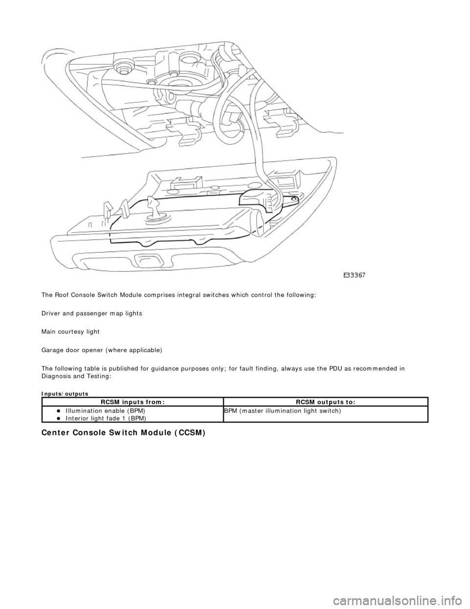
The Roof Console Switch Module comprises integral switches which control the following:
Driver and passenger map lights
Main courtesy light
Garage door opener (where applicable)
The following table is published for guidance purp oses only; for fault finding, always use the PDU as recommended in
Diagnosis and Testing:
Inputs/outputs
Center Console Switch Module (CCSM)
RCSM inputs from:RCSM outputs to:
Illumination enable (BPM) Interior light fade 1 (BPM) BPM (master illumination light switch)
Page 2012 of 2490
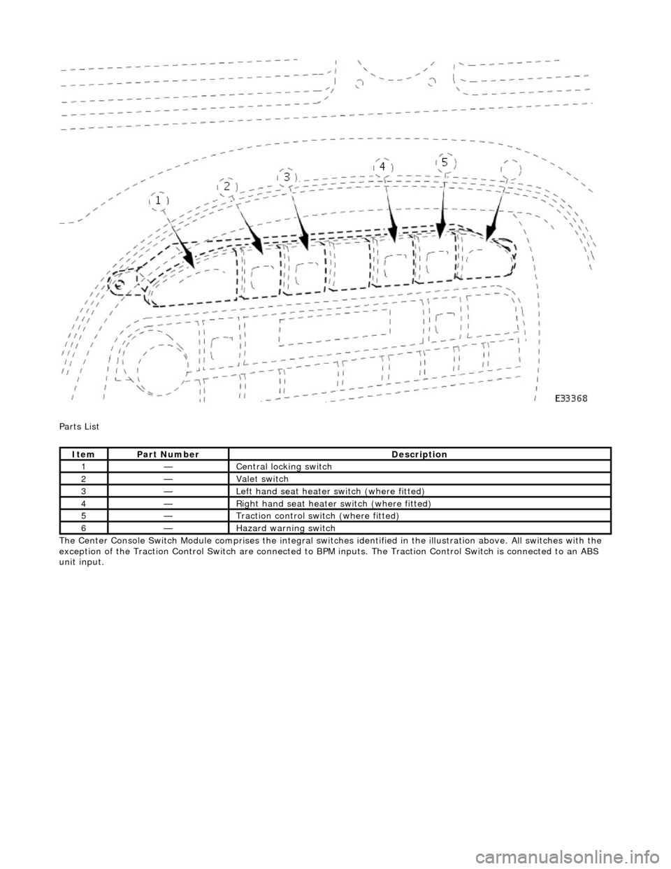
Parts List
The Center Console Switch Module comprises the integral switches identified in the illustration above. All switches with the
exception of the Traction Control Switch are connected to BPM inputs. The Traction Control Switch is connected to an ABS
unit input.
ItemPart NumberDescription
1—Central locking switch
2—Valet switch
3—Left hand seat heater switch (where fitted)
4—Right hand seat heater switch (where fitted)
5—Traction control switch (where fitted)
6—Hazard warning switch
Page 2013 of 2490
Multifunction Electronic Modules - Multifunction Electronic Module
Diagnosis and Testing
Tests Using the Portable Diagnostic Unit
Refer to PDU User Guide
The complexity of the electronics involved with the various Electronic Control Modules and the multiplexed communication
networks, preclude the use of workshop general electrical test equipment. Therefore, reference should be made to the PDU
User Guide for detailed instructions on test ing control modules.
The PDU systematically test s and analyses the control modules and th e associated electrical connections.
Where a fault involving a control module is indicated by the PDU, before replacing the component, some basic diagnostic
methods may be necessary to confirm that connecti ons are good and that wiring is not damaged.
Page 2014 of 2490
Multifunction Electronic Modules - Front Door Module (FDM)
Removal and Installation
Removal
Installation
1.
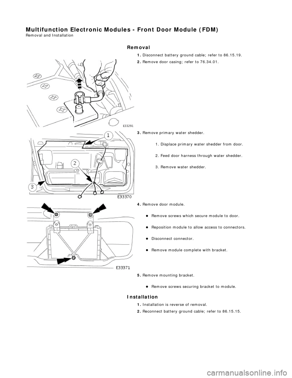
Disconnect battery ground cable; refer to 86.15.19.
2. Remove door casing; refer to 76.34.01.
3. Remove primary water shedder.
1. Displace primary water shedder from door.
2. Feed door harness through water shedder.
3. Remove water shedder.
4. Remove door module.
Remove screws which secu re module to door.
Reposition module to allow access to connectors.
Disconnect connector.
Remove module complete with bracket.
5. Remove mounting bracket.
Remove screws securing bracket to module.
1. Installation is reverse of removal.
2. Reconnect battery ground cable; refer to 86.15.15.
Page 2015 of 2490
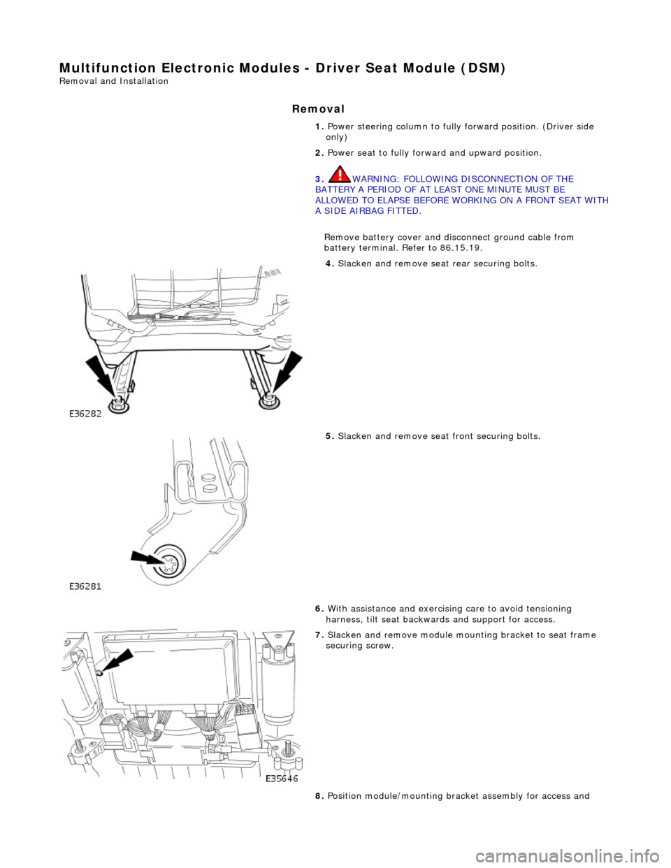
Multifunction Electronic Modules - Driver Seat Module (DSM)
Removal and Installation
Removal
1. Power steering column to fully forward position. (Driver side
only)
2. Power seat to fully forward and upward position.
3. WARNING: FOLLOWING DISCONNECTION OF THE
BATTERY A PERIOD OF AT LEAST ONE MINUTE MUST BE
ALLOWED TO ELAPSE BEFORE WORKING ON A FRONT SEAT WITH
A SIDE AIRBAG FITTED.
Remove battery cover and disc onnect ground cable from
battery terminal. Refer to 86.15.19.
4. Slacken and remove seat rear securing bolts.
5. Slacken and remove seat front securing bolts.
6. With assistance and exercising care to avoid tensioning
harness, tilt seat backwa rds and support for access.
7. Slacken and remove module moun ting bracket to seat frame
securing screw.
8. Position module/mounting bracket assembly for access and
Page 2016 of 2490

Installation
slacken and remove module to bracket securing screws.
9.
Remove seat control module.
1. Disconnect harness multiplugs from module.
2. Withdraw module from seat
1. Position control module at seat and connect harness
multiplugs.
2. Position control module on mounting bracket and fit and
tighten securing screws.
3. Position control module/mountin g bracket assembly on seat
frame and fit and tighten securing screw.
4. Position seat over se curing bolt holes.
5. Fit and tighten seat front securing bolts
6. Fit and tighten seat re ar securing bolts.
7. Connect ground cable to battery terminal and fit battery cover.
Refer to 86.15.15.
8. Return seat to original position.
9. Return steering column to original position.
Page 2017 of 2490
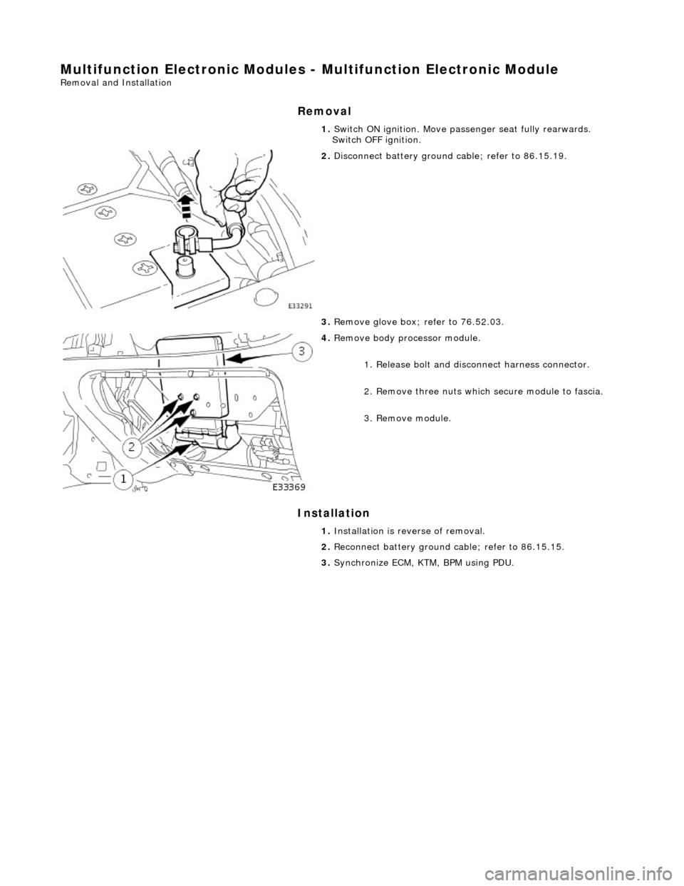
Multifunction Electronic Modules - Multifunction Electronic Module
Removal and Installation
Removal
Installation
1.
Switch ON ignition. Move pass enger seat fully rearwards.
Switch OFF ignition.
2. Disconnect battery ground cable; refer to 86.15.19.
3. Remove glove box; refer to 76.52.03.
4. Remove body processor module.
1. Release bolt and discon nect harness connector.
2. Remove three nuts which secure module to fascia.
3. Remove module.
1. Installation is reverse of removal.
2. Reconnect battery ground cable; refer to 86.15.15.
3. Synchronize ECM, KTM, BPM using PDU.
Page 2018 of 2490

Multifunction Electronic Modules - Rear Door Module (RDM)
Removal and Installation
Removal
Installation
1. Disconnect battery ground cable; refer to 86.15.19.
2. Remove door casing; refer to 76.34.04.
3. Remove primary water shedder.
1. Displace primary water shedder from door.
2. Feed door harness through water shedder.
3. Remove water shedder.
4. Remove door module.
Remove screws which secu re module to door.
Reposition module to allow access to connectors.
Disconnect connectors.
1. Installation is reverse of removal.
2. Reconnect battery ground cable; refer to 86.15.15.
Page 2019 of 2490
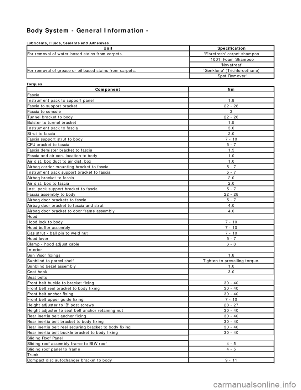
Body System - General Information -
Lubricants, Fluids, Sealants and Adhesives
Torques
UnitSpecification
For removal of water-based stains from carpets.'Fibrefresh' carpet shampoo
'1001' Foam Shampoo
'Novatreat'
For removal of grease or oil based stains from carpets.'Genklene' (Trichloroethane)
'Spot Remover'
ComponentNm
Fascia
Instrument pack to support panel1.8
Fascia to support bracket22 - 28
Fascia to console3
Tunnel bracket to body22 - 28
Bolster to tunnel bracket1.5
Instrument pack to fascia3.0
Strut to fascia2.0
Fascia support strut to body7 - 10
CPU bracket to fascia5 - 7
Fascia demister bracket to fascia1.5
Fascia and air con. location to body1.0
Air dist. box duct to air dist. box1.0
Airbag carrier mounting bracket to fascia5 - 7
Instrument pack suppo rt bracket to fascia5 - 7
Airbag bracket to fascia2.0
Air dist. box to fascia2.0
Inst. pack support bracket to fascia5 - 7
Fascia assembly to body22 - 28
Airbag door brackets to fascia5 - 7
Airbag door bracket to fascia and strut4.0
Airbag door bracket to door frame assembly4.0
Hood
Hood lock to body7 - 10
Hood buffer assembly7 - 10
Gas strut - ball pin to weld nut7 - 10
Hood lever5 - 7
Clamp - hood adjust cable6 - 8
Interior
Sun Visor fixings1.8
Sunblind to parcel shelfTighten to prevailing torque.
Sunblind bezel assembly1.0
Coat hook3.0
Seat belts
Front belt buckle to bracket fixing30 - 40
Front belt reel bracket to body fixing30 - 40
Front belt anchor fixing30 - 40
Front belt upper guide fixing7 - 10
Height adjuster to 'B' post screws23 - 27
Height adjuster to seat belt anchor retaining nut30 - 40
Rear inertia belt anchor fixing30 - 40
Rear inertia belt bracket to body fixing30 - 40
Rear inertia belt reel secu ring bracket to body fixing30 - 40
Rear inertia belt buckle bracket to body fixing30 - 40
Sliding Roof Panel
Sliding roof assembly frame to BIW roof4 - 5
Sliding roof panel to frame4 - 5
Trunk
Compact disc autochanger bracket to body9 - 11
Page 2020 of 2490
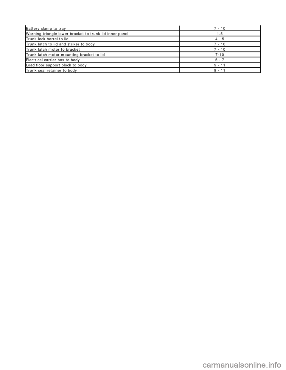
Battery clamp to tray7 - 10
Warning triangle lower bracket to trunk lid inner panel1.5
Trunk lock barrel to lid4 - 5
Trunk latch to lid and striker to body7 - 10
Trunk latch motor to bracket7 - 10
Trunk latch motor mounting bracket to lid7-10
Electrical carrier box to body5 - 7
Load floor support block to body9 - 11
Trunk seal retainer to body9 - 11