JAGUAR XFR 2010 1.G Workshop Manual
XFR 2010 1.G
JAGUAR
JAGUAR
https://www.carmanualsonline.info/img/21/7642/w960_7642-0.png
JAGUAR XFR 2010 1.G Workshop Manual
Trending: P0460-15, mileage, B100A63, transmissio oil temperature sensor, fuse box diagram, towing, b1b33
Page 2211 of 3039
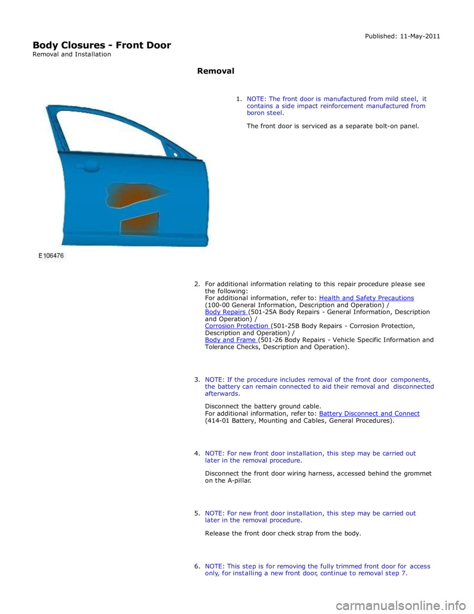
(100-00 General Information, Description and Operation) /
Body Repairs (501-25A Body Repairs - General Information, Description and Operation) /
Corrosion Protection (501-25B Body Repairs - Corrosion Protection, Description and Operation) /
Body and Frame (501-26 Body Repairs - Vehicle Specific Information and Tolerance Checks, Description and Operation).
3. NOTE: If the procedure includes removal of the front door components,
the battery can remain connected to aid their removal and disconnected
afterwards.
Disconnect the battery ground cable.
For additional information, refer to: Battery Disconnect and Connect (414-01 Battery, Mounting and Cables, General Procedures).
4. NOTE: For new front door installation, this step may be carried out
later in the removal procedure.
Disconnect the front door wiring harness, accessed behind the grommet
on the A-pillar.
5. NOTE: For new front door installation, this step may be carried out
later in the removal procedure.
Release the front door check strap from the body.
6. NOTE: This step is for removing the fully trimmed front door for access
only, for installing a new front door, continue to removal step 7.
Page 2212 of 3039
Motor (501-11 Glass, Frames and Mechanisms, Removal and Installation).
8. Remove the exterior mirror.
For additional information, refer to: Exterior Mirror (501-09 Rear View Mirrors, Removal and Installation).
9. Remove the front door latch.
For additional information, refer to: Front Door Latch (501-14 Handles, Locks, Latches and Entry Systems, Removal and Installation).
10. Remove the front door outer window frame mouldings.
11. Remove the front door weatherstrips.
12. Remove the front door wiring harness.
13. Remove the front door impact absorbers.
14. Remove the front door check strap.
15. Remove the front door glass run felt.
Page 2213 of 3039
16. Remove any miscellaneous front door clips, grommets and blanking
covers.
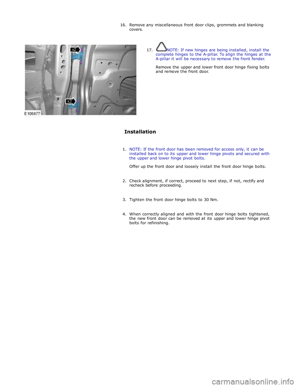
17. NOTE: If new hinges are being installed, install the
complete hinges to the A-pillar. To align the hinges at the
A-pillar it will be necessary to remove the front fender.
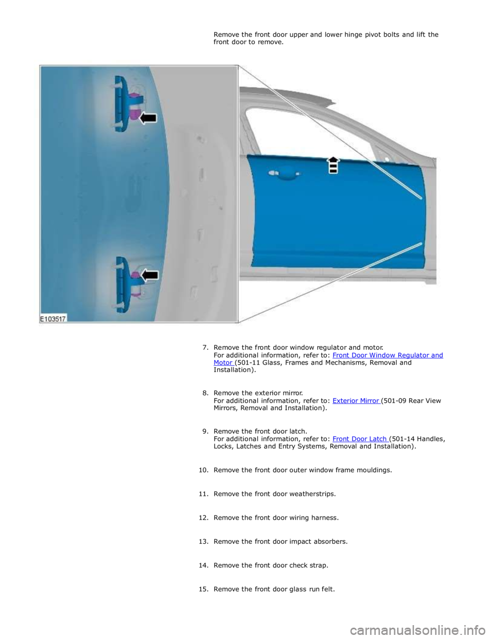
Remove the upper and lower front door hinge fixing bolts
and remove the front door.
Installation
1. NOTE: If the front door has been removed for access only, it can be
installed back on to its upper and lower hinge pivots and secured with
the upper and lower hinge pivot bolts.
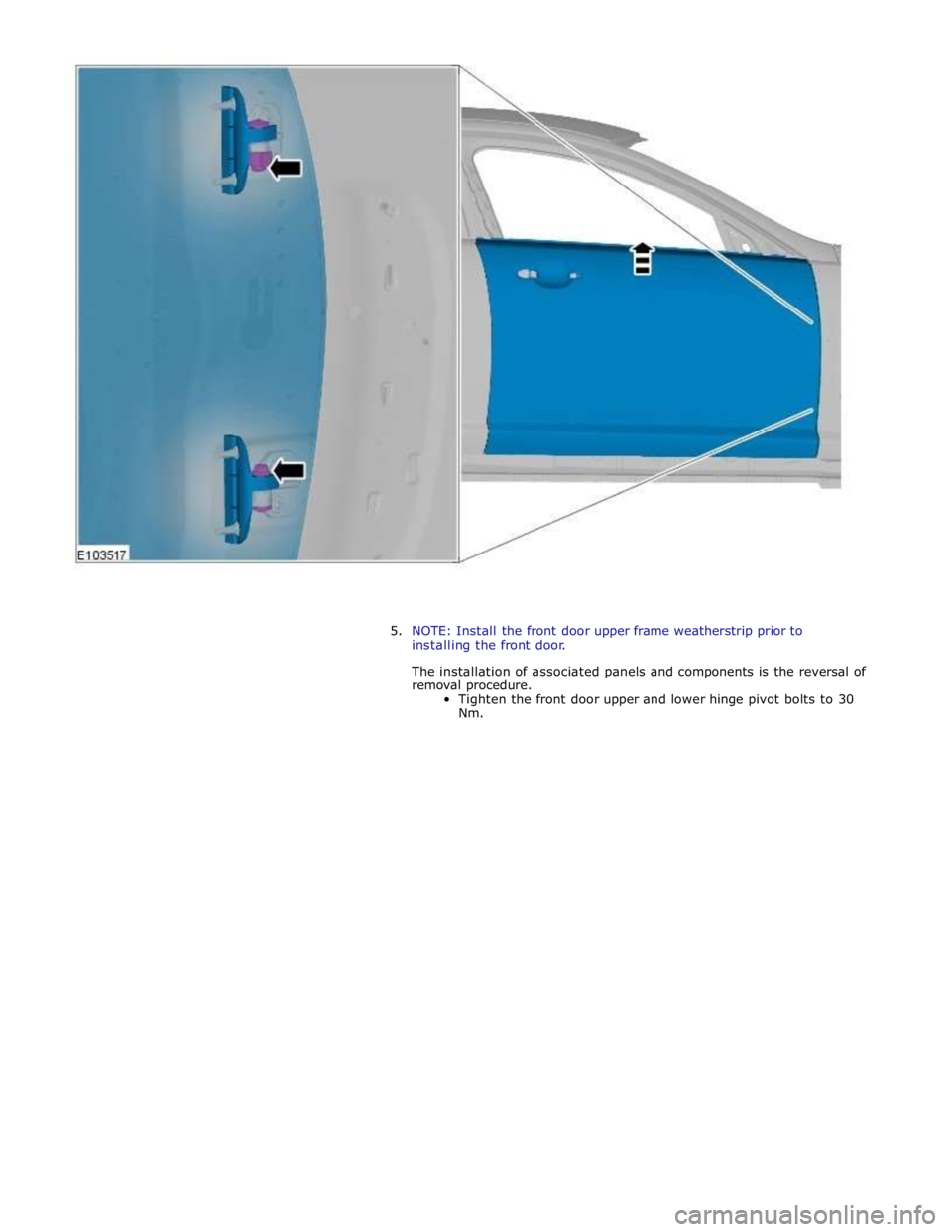
Offer up the front door and loosely install the front door hinge bolts.
2. Check alignment, if correct, proceed to next step, if not, rectify and
recheck before proceeding.
3. Tighten the front door hinge bolts to 30 Nm.
4. When correctly aligned and with the front door hinge bolts tightened,
the new front door can be removed at its upper and lower hinge pivot
bolts for refinishing.
Page 2214 of 3039
Page 2215 of 3039
Body Closures - Fuel Filler Door
Removal and Installation
Removal
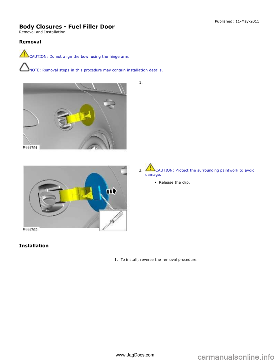
CAUTION: Do not align the bowl using the hinge arm.
NOTE: Removal steps in this procedure may contain installation details.
1. Published: 11-May-2011
Installation
2. CAUTION: Protect the surrounding paintwork to avoid
damage.
Release the clip.
1. To install, reverse the removal procedure. www.JagDocs.com
Page 2216 of 3039
Body Closures - Fuel Filler Door Assembly
Removal and Installation
Removal
CAUTION: Do not align the bowl using the hinge arm.
NOTE: Removal steps in this procedure may contain installation details. Published: 11-May-2011
1. WARNING: Do not work on or under a vehicle supported only by a jack.
Always support the vehicle on safety stands.
Raise and support the vehicle.
2. Refer to: Fuel Tank Filler Pipe (310-01, Removal and Installation).
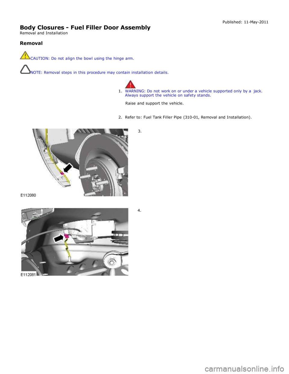
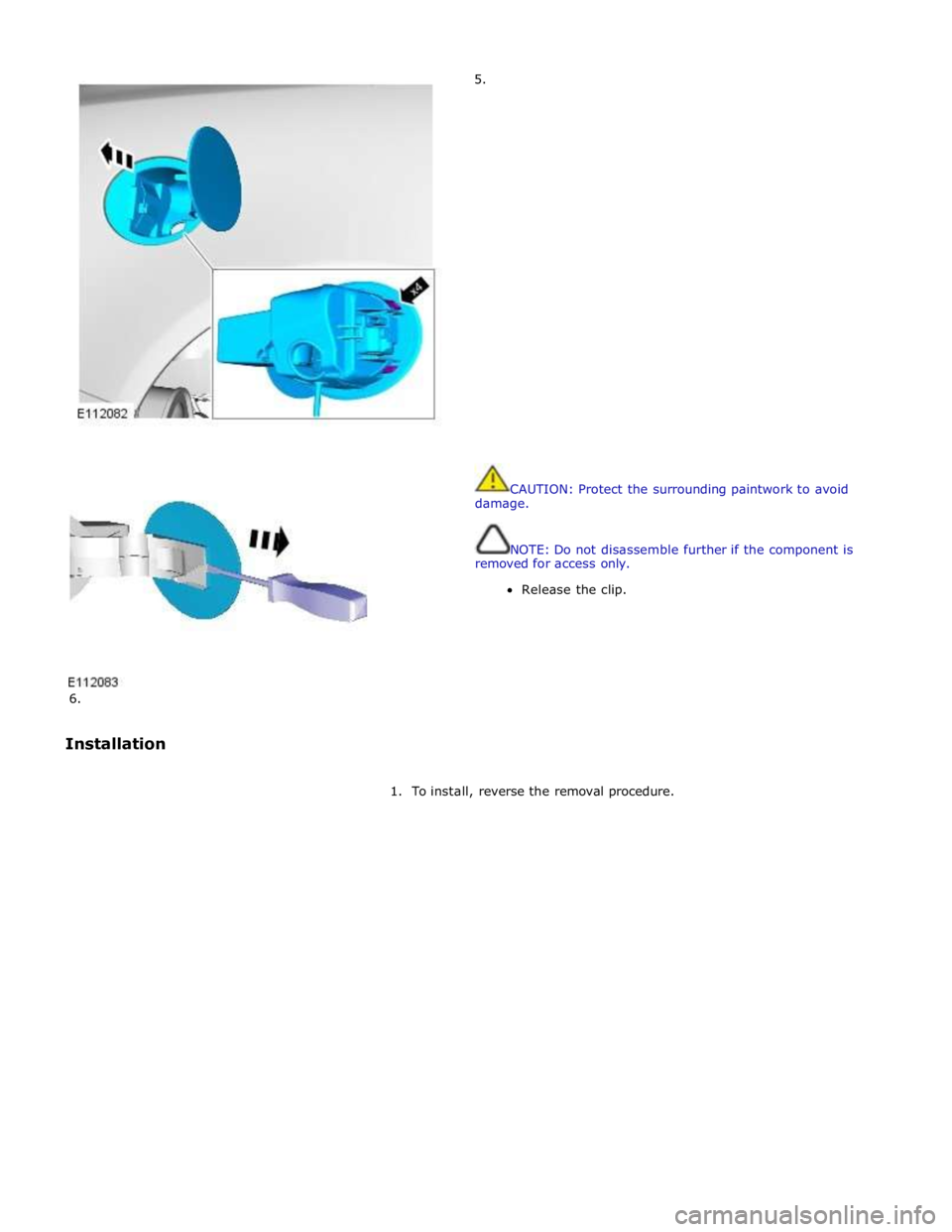
3.
4.
Page 2217 of 3039
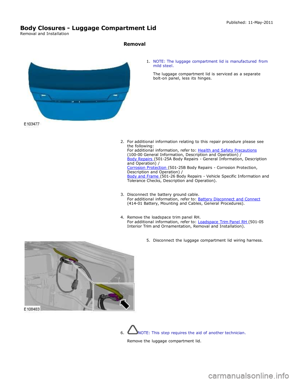
6.
Installation 5.
CAUTION: Protect the surrounding paintwork to avoid
damage.
NOTE: Do not disassemble further if the component is
removed for access only.
Release the clip.
1. To install, reverse the removal procedure.
Page 2218 of 3039
(100-00 General Information, Description and Operation) /
Body Repairs (501-25A Body Repairs - General Information, Description and Operation) /
Corrosion Protection (501-25B Body Repairs - Corrosion Protection, Description and Operation) /
Body and Frame (501-26 Body Repairs - Vehicle Specific Information and Tolerance Checks, Description and Operation).
3. Disconnect the battery ground cable.
For additional information, refer to: Battery Disconnect and Connect (414-01 Battery, Mounting and Cables, General Procedures).
4. Remove the loadspace trim panel RH.
For additional information, refer to: Loadspace Trim Panel RH (501-05 Interior Trim and Ornamentation, Removal and Installation).
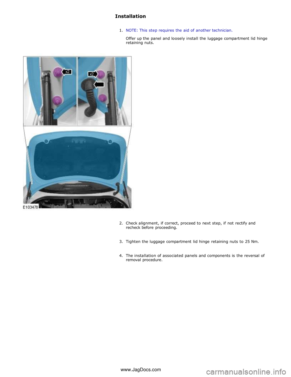
5. Disconnect the luggage compartment lid wiring harness.
6. NOTE: This step requires the aid of another technician.
Remove the luggage compartment lid.
Page 2219 of 3039
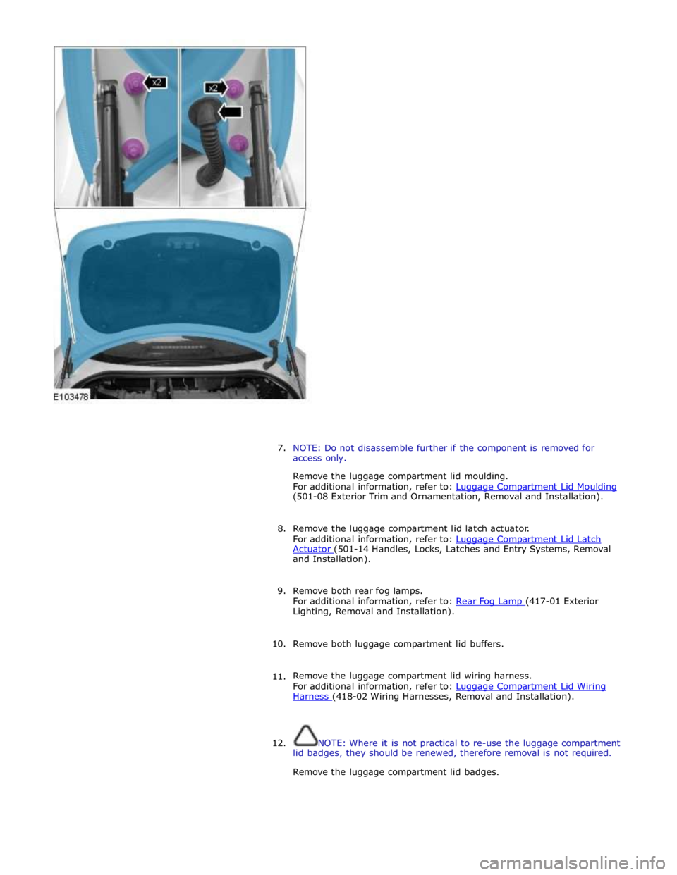
7. NOTE: Do not disassemble further if the component is removed for
access only.
Remove the luggage compartment lid moulding.
For additional information, refer to: Luggage Compartment Lid Moulding (501-08 Exterior Trim and Ornamentation, Removal and Installation).
8. Remove the luggage compartment lid latch actuator.
For additional information, refer to: Luggage Compartment Lid Latch Actuator (501-14 Handles, Locks, Latches and Entry Systems, Removal and Installation).
9. Remove both rear fog lamps.
For additional information, refer to: Rear Fog Lamp (417-01 Exterior Lighting, Removal and Installation).
10. Remove both luggage compartment lid buffers.
11. Remove the luggage compartment lid wiring harness.
For additional information, refer to: Luggage Compartment Lid Wiring Harness (418-02 Wiring Harnesses, Removal and Installation).
12. NOTE: Where it is not practical to re-use the luggage compartment
lid badges, they should be renewed, therefore removal is not required.
Remove the luggage compartment lid badges.
Page 2220 of 3039
Trending: roof rack, open gas tank, technical data, Rear Drive Axle and Differential, B1c39-2, antifreeze, C1a04-22

