MAZDA PROTEGE 1992 Workshop Manual
Manufacturer: MAZDA, Model Year: 1992, Model line: PROTEGE, Model: MAZDA PROTEGE 1992Pages: 1164, PDF Size: 81.9 MB
Page 171 of 1164

ENGINE STAND MOUNTING B2
PROCEDURE
Step 1
1. Remove in the order shown in the figure.
r
GASKET, REPLACE
1. Exhaust manifold insulator
2. Exhaust manifold
3. Water bypass pipe
OSUOBX-084
4. A/C compressor bracket (if equipped)
5. Water inlet pipe
6. Exhaust pipe bracket
Step 2
Caution
l When installing the SST (engine hanger), use the
holes shown in the figure.
82-39
Page 172 of 1164

B2 ENGINE STAND MOUNTING
051JOBX-08
05UOBX.086
20mm (0.79 in 20mm (0.79 in
05UOEX-OE
05UOBX-01
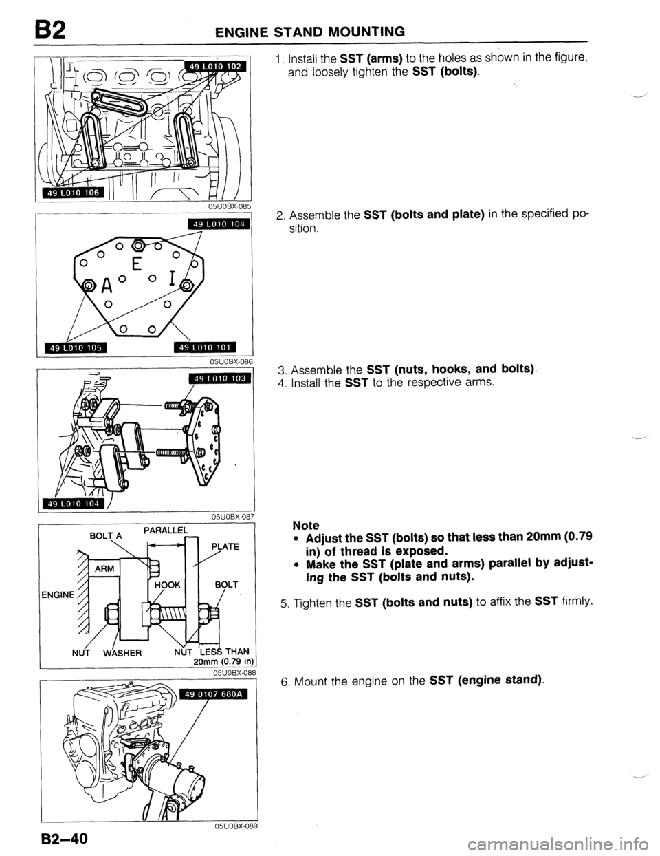
1. Install the SST (arms) to the holes as shown in the figure,
and loosely tighten the
SST (bolts).
2. Assemble the SST (bolts and plate) in the specified po-
sition.
3. Assemble the
SST (nuts, hooks, and bolts).
4. Install the SST to the respective arms.
Note
l Adjust the SST (bolts) so that less than 20mm (0.79
in) of thread is exposed.
l Make the SST (plate and arms) parallel by adjust-
ing the SST (bolts and nuts).
5. Tighten the SST (bolts and nuts) to affix the SST firmly.
6. Mount the engine on the
SST (engine stand).
82-40
Page 173 of 1164

DISASSEMBLY B2
DISASSEMBLY
PREPARATION
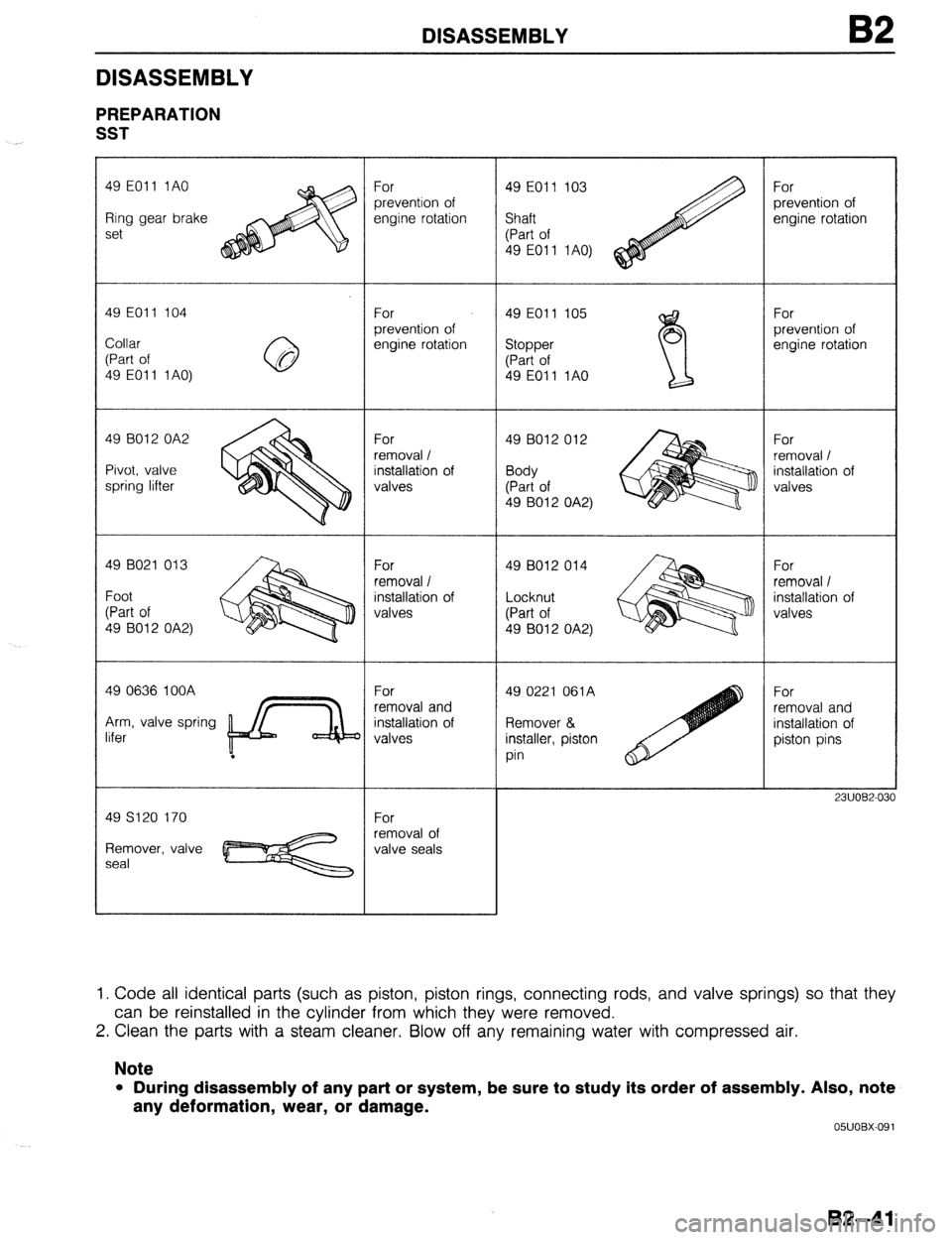
SST
._
49 EOll 1AO
Ring gear brake
set
49 EOll 104
Collar
(Part of
49 EOI 1 1 AO)
49 8012 OA2
Pivot, valve
spring lifter
49 B021 013
Foot
(Part of
49 B012 OA2)
49 0636 IOOA
Arm, valve spring
lifer
.
Remover, valve
seal For
prevention of
engine rotation
For
prevention of
engine rotation
For
removal /
installation of
valves
For
removal /
installation of
valves
For
removal and
installation of
valves
For
removal of
valve seals 49 EOll 103
Shaft
(Part of
49 EOll 1AO)
49 EOll 105 49 EOll 105
Stopper Stopper 0
(Part of (Part of
49 E011 1AO 49 E011 1AO
w
49 B012 012
Body
(Part of
49 8012 OA2)
49 8012 014
Locknut
(Part of
49 8012 OA2)
49 0221 061A
Remover &
installer, piston
pin For
prevention of
engine rotation
For
prevention of
engine rotation
For
removal /
installation of
valves
For
removal /
installation of
valves
For
removal and
installation of
piston pins
2311082.03
1. Code all identical parts (such as piston, piston rings, connecting rods, and valve springs) so that they
can be reinstalled in the cylinder from which they were removed.
2. Clean the parts with a steam cleaner. Blow off any remaining water with compressed air.
Note
l During disassembly of any part or system, be sure to study its order of assembly. Also, note
any deformation, wear, or damage.
05UOBX-091
B2-41
Page 174 of 1164

B2 DISASSEMBLY
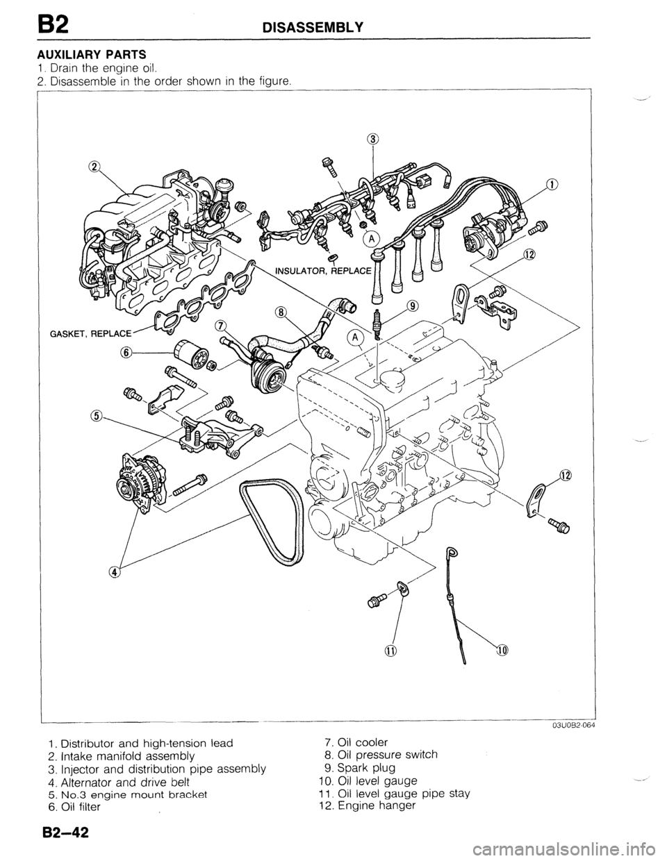
AUXILIARY PARTS
1, Drain the engine oil.
2. Disassemble in the order shown in the figure
GASKET, REPLACE ..______-.
-___ -
03UOB2-064
1. Distributor and high-tension lead 7. Oil cooler
2. Intake manifold assembly 8. Oil pressure switch
3. Injector and distribution pipe assembly 9. Spark plug
4. Alternator and drive belt 10. Oil level gauge
5. No.3 engine mount bracket 11. Oil level gauge pipe stay
6. Oil filter 12. Engine hanger
82-42
Page 175 of 1164

DISASSEMBLY 82
TIMING BELT
1. Disassemble in the order shown in the figure, referring to Disassembly Note.
23UOB2-0:
1. Water pump pulley
2. Crankshaft pulley
3. Timing belt cover, upper
4. Timing belt cover, middle
5. Timing belt cover, lower
6. Pulley lock bolt
7. Pulley boss
8. Timing belt
Disassembly Note . . . . . . . . . . . . . . . . . . . . page B2-44
9. Tensioner and tensioner spring
10. Idler
Disassembly Note . . . . . . . . . . . . . . . . . . . . page B2-44
B2-43
Page 176 of 1164

B2 DISASSEMBLY
23UOB2-055
13EOB2-030
Disassembly Note
Pulley lock bolt
1. Hold the flywheel (MTX) or drive plate (ATX) with the SST
or equivalent.
2. Loosen the pulley lock bolt.
3. Remove the pulley lock bolt.
Timing belt
1. Loosen the tensioner lock bolt and using a suitable bar, pry
the tensioner outward.
Caution
l Protect the tensioner with a rag before prying.
2. Tighten the lock bolt with the tensioner spring fully extended.
Note
l Mark the timing belt rotation for proper reinstal-
lation.
3. Remove the timing belt.
82-44
Page 177 of 1164

DISASSEMBLY B2
CYLINDER HEAD
1. Disassemble in the order shown in the figure, referring to Disassembly Note.
OIL SEAL, REPLACE
GASKET, REPLACE
1. Cylinder head cover 11. Cylinder head
2. Camshaft pulley Inspection . . . . . . . . . . . . . . . . . . . . . . . . . . . . . . . . . page B2-54
Disassembly Note . . . .., ,.... . . . . . . . . . page 82-46 12. Cylinder head gasket
Inspection . . . . . . . . . . . . . . . .., . . . . . . . . . . . . . page 82-65 13. Valve keeper
3. Seal plate Disassembly Note . . . . . . . . . . . . . . . . . . . . page B2-46
4. Camshaft 14. Valve spring seat, upper
Disassembly Note . . . . . . . . . . . . . . . . . . . . page 82-46 15. Valve spring
Inspection . . . . . . . . . . . . . . . . . . . . . . . . . . . . . . . . . page B2-58 Inspection . . . . . . . . . . . . . . . . . . . . . . . . . . . . . . . . . page 82-58
5. HLA 16. Valve spring seat, lower
Disassembly Note . . . . . . . . . . . . . . . . . . . . page B2-46 17. Valve
Inspection ,........,,..,.,....,..,,.,..,... page B2-60 Inspection ..,.............................. page 82-55
6. Thermostat cover 18. Valve seal
7. Thermostat Disassembly Note ..,................. page B2-47
8. Water thermoswitch Inspect for wear or damage
9. Heat gauge unit 19. Valve guide
IO. Cylinder head bolt Inspection . . . . . . . . . . . . . . . . . . . . . . . . . . . . . . . . . page B2-55
Disassembly Note . . . . . . . . . . . . . . . . . . . . page 82-46 Replacement . . . . . . . . . . . . . . . . . . . . . . . . . . . . page B2-56
82-45
Page 178 of 1164

82 DISASSEMBLY
2311082-03
r HLA
r
05UOBX-04!
2311082-03
I
05UOBX-1C
82-46
Disassembly Note
Camshaft pulley
1, Hold the camshaft with a wrench at hexagonal portion.
2. Remove the camshaft pulley lock bolt.
3. Remove the camshaft pulley.
Camshaft
1. Loosen the camshaft cap bolts in two or three steps in the
order shown in the figure.
2. Remove the camshaft caps
3. Remove the camshaft.
4. Remove the camshaft oil seal from the camshaft.
Caution
l Mark the HLA with a felt pen so that they can be reln-
stalled in the position from which they were
removed.
1. Remove the HLA from the cylinder head.
Cylinder head bolts
1. Loosen the cylinder head bolts in two or three steps in the
order shown in the figure.
2. Remove the cylinder head bolts.
Valve keeper
1. Set the SST against the upper valve spring seat as shown
in the figure.
2. Remove the valve keepers.
Page 179 of 1164

DISASSEMBLY 82
Valve seal
1 I Remove the valve seal with the SST.
02-47
Page 180 of 1164

B2 DISASSEMBLY
CYLINDER BLOCK (EXTERNAL PARTS)
1. Disassemble in the order shown in the figure, referring to Disassembly Note.
I
@ma @a% GASST, REPLACE
GASKET,
REPLACE
/
d I @REPLACE
23UOB2-0
1. Water pump
Service ..,....,..,......,.,.,,.....,,.,.......... Section E
2. Timing belt pulley and lock bolt
Disassembly Note . . . . . ..,.,........,. page 82-49
Inspection . . . . . . . . . . . . . . . . . . . . . . . . . . . . . . . . . page 82-65
3. Clutch cover, clutch disc (MTX)
Service . . . , , . . . . . . . . . . . . . . . . . . . . . . . . . . . . . . . . . . . . . Section H
4. Flywheel (MTX)
Disassembly Note ,.. . . . . . . . . . . . . . . . . . page 82-49
Inspect for wear or damage
5. Backing plate, drive plate, and adapter (ATX)
Disassembly Note . . . . ,., ,..... . . . . . . . page B2-49
6. End plate 7. Oil pan and gasket
Disassembly Note .,.................. page 82-49
Inspect for damage
8. Oil strainer
9. Main bearing support plate (MBSP)
Disassembly Note . . . ., . . . . . ..,.... . . . page B2-50
Inspect for damage
10. Oil pump
Service . . . , . . . . . . . . . . . . . . . . . . . . . . . . . . . . . . . . . . . . . . Section D
11. Front oil seal
Disassembly Note .,.................. page 82-50
12. Rear cover
13. Rear oil seal
Disassembly Note . . . . . . . . . . . . . . . . . . . . page B2-50
B2--48