MAZDA PROTEGE 1992 Workshop Manual
Manufacturer: MAZDA, Model Year: 1992, Model line: PROTEGE, Model: MAZDA PROTEGE 1992Pages: 1164, PDF Size: 81.9 MB
Page 191 of 1164
INSPECTION / REPAIR B2
23UOB2-06
051JOBX.14
05UOBX.14
OWOBX-14
05UOBX-14
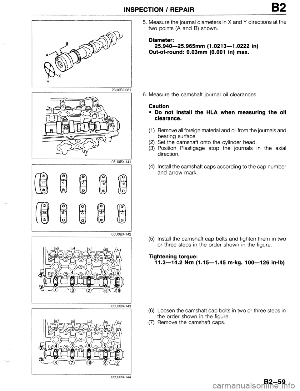
5. Measure the journal diameters in X and Y directions at the
two points (A and 8) shown.
Diameter:
25.940-25.965mm (1.0213-l .0222 in)
Out-of-round: 0.03mm (0.001 in) max.
6. Measure the camshaft journal oil clearances.
Caution
l Do not install the HLA when measuring the oil
clearance.
(1) Remove all foreign material and oil from the journals and
bearing surface.
(2) Set the camshaft onto the cylinder head.
(3) Position Plastigage atop the journals in the axial
direction.
(4) Install the camshaft caps according to the cap number
and arrow mark.
(5) Install the camshaft cap bolts and tighten them in two
or three steps in the order shown in the figure.
Tightening torque:
11.3-14.2 N-m (1.15-l .45 m-kg, loo-126 in-lb)
(6) Loosen the camshaft cap bolts in two or three steps in
the order shown in the figure.
(7) Remove the camshaft caps.
82-59
Page 192 of 1164
B2 INSPECTION / REPAIR
r--
1
05UOBX-14
I -
L
05UOBX-149
82-60
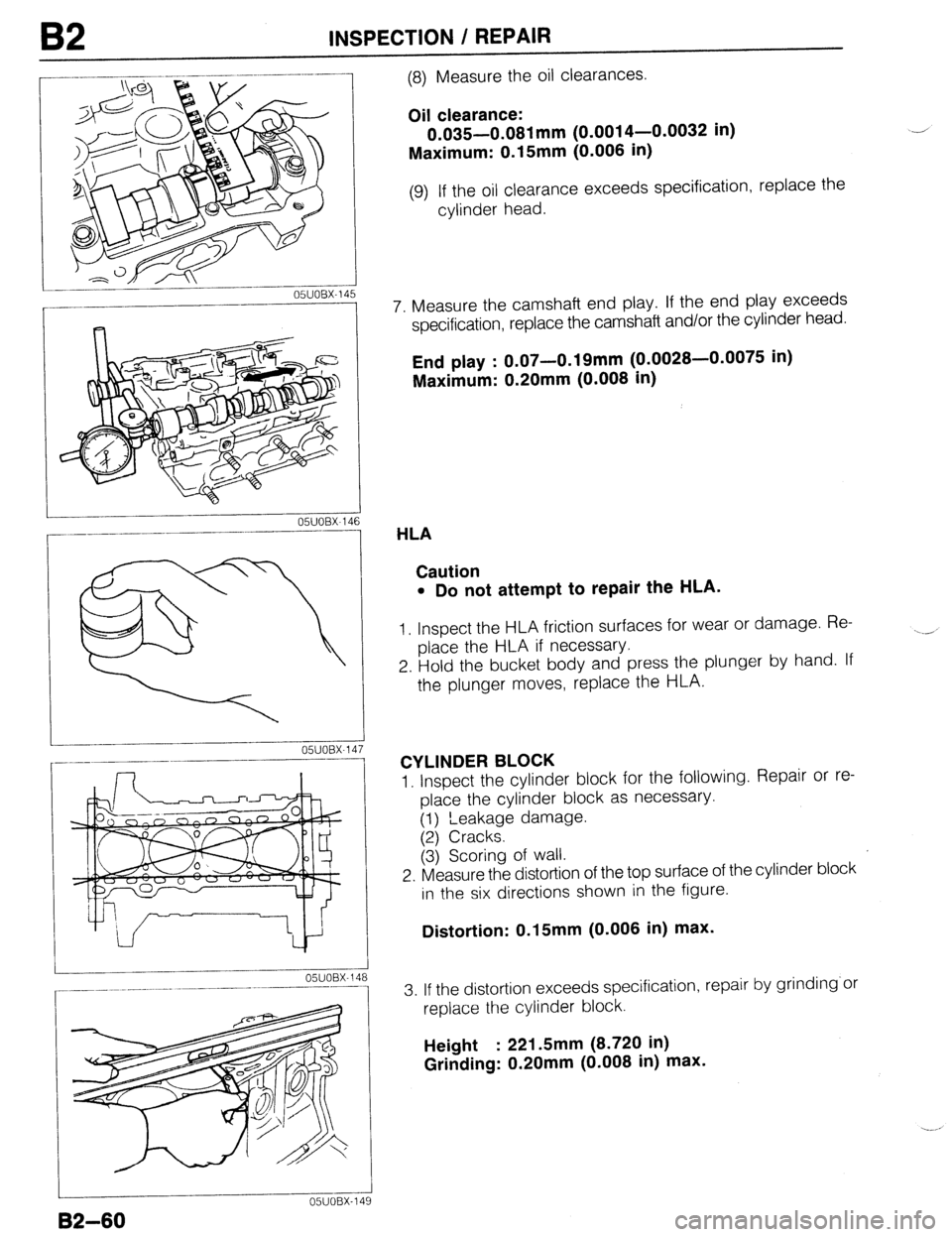
(8) Measure the oil clearances.
Oil clearance:
0.035-0.081 mm (0.0014-0.0032 in)
Maximum: 0.15mm (0.006 in)
(9) If the oil clearance exceeds specification, replace the
cylinder head.
7. Measure the camshaft end play. If the end play exceeds
specification, replace the camshaft and/or the cylinder head.
End play : 0.07-0.19mm (0.0028-0.0075 in)
Maximum: 0.20mm (0.008 in)
HLA
Caution
l Do not attempt to repair the HLA.
1, Inspect the HLA friction surfaces for wear or damage. Re-
place the HLA if necessary.
2. Hold the bucket body and press the plunger by hand. If
the plunger moves, replace the HLA.
CYLINDER BLOCK
1. Inspect the cylinder block for the following. Repair or re-
place the cylinder block as necessary.
(1) ‘Leakage damage.
(2) Cracks.
(3j Scoring of wall.
2. Measure the distortion of the top surface of the cylinder block
in the six directions shown in the figure.
Distortion: 0.15mm (0.006 in) max.
3. If the distortion exceeds specification, repair by grinding’or
replace the cylinder block.
Height : 221 Smm (8.720 in)
Grinding: 0.20mm (0.008 in) max.
Page 193 of 1164
INSPECTION / REPAIR B2
A ,-
B
C
I
03UOB2-099
OWOBX-151
1
I
OSJOBX-15
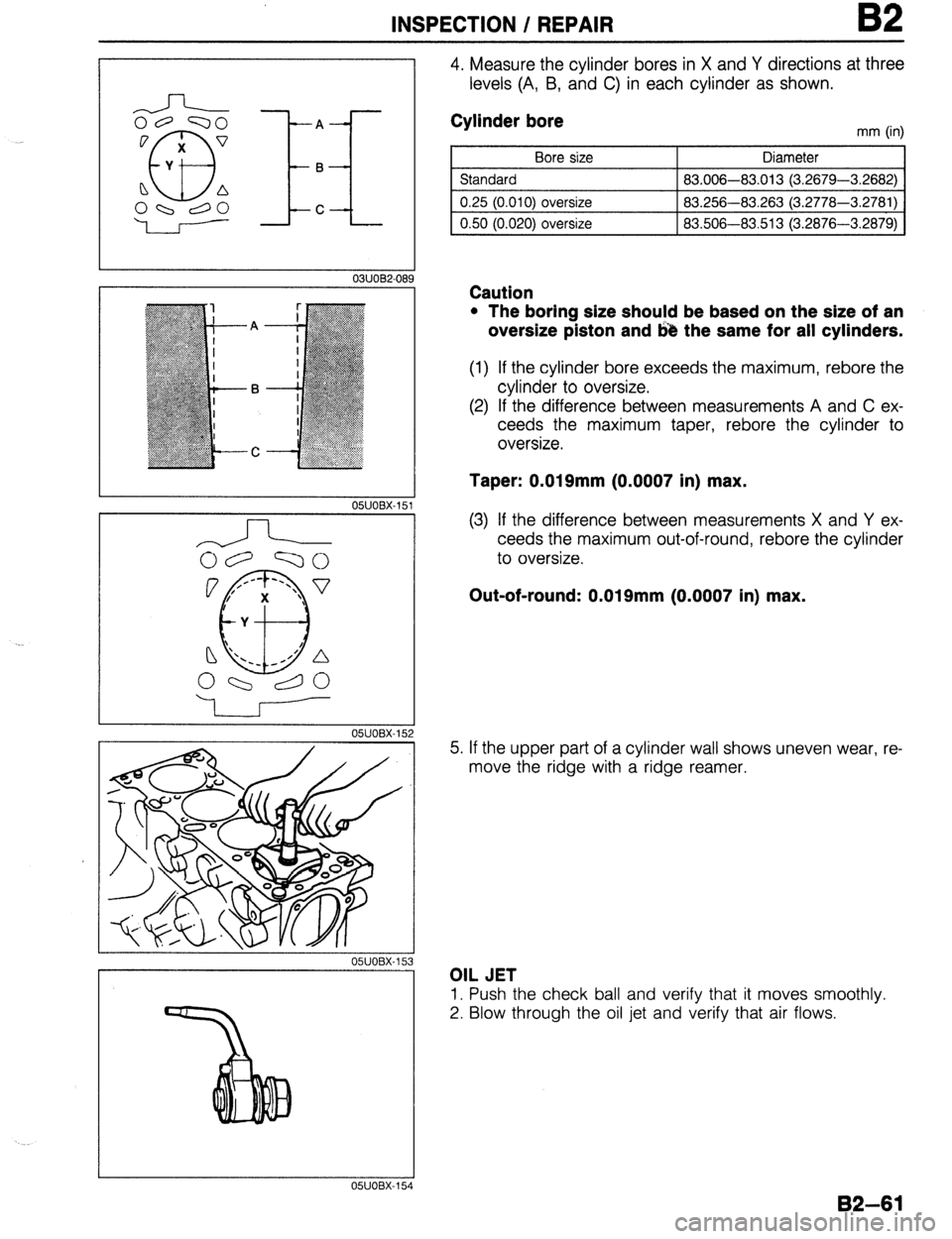
4. Measure the cylinder bores in X and Y directions at three
levels (A, B, and C) in each cylinder as shown.
Cylinder bore
Bore size
Standard
0.25 (0.010) oversize
0.50 (0.020) oversize mm (in)
Diameter
83.006-83.013 (3.2679-3.2682)
83.256-83.263 (3.2778-3.2781)
83.506-83.513 (3.2876-3.2879)
Caution
l The boring size should be based on the size of an
oversize piston and 643 the same for all cylinders.
(1) If the cylinder bore exceeds the maximum, rebore the
cylinder to oversize.
(2) If the difference between measurements A and C ex-
ceeds the maximum taper, rebore the cylinder to
oversize.
Taper: 0.019mm (0.0007 in) max.
(3) If the difference between measurements X and Y ex-
ceeds the maximum out-of-round, rebore the cylinder
to oversize.
Out-of-round: 0.019mm (0.0007 in) max.
5. If the upper part of a cylinder wall shows uneven wear, re-
move the ridge with a ridge reamer.
OIL JET
1. Push the check ball and verify that it moves smoothly.
2. Blow through the oil jet and verify that air flows.
05UOBX-15
82-61
Page 194 of 1164
B2 INSPECTION / REPAIR
OIL RIN
GROOV
16Smm
(0.650 in
UTER DIAMETER
Caution
l If the piston Is replaced, the plston rings must also
be replaced.
03UOB2-090
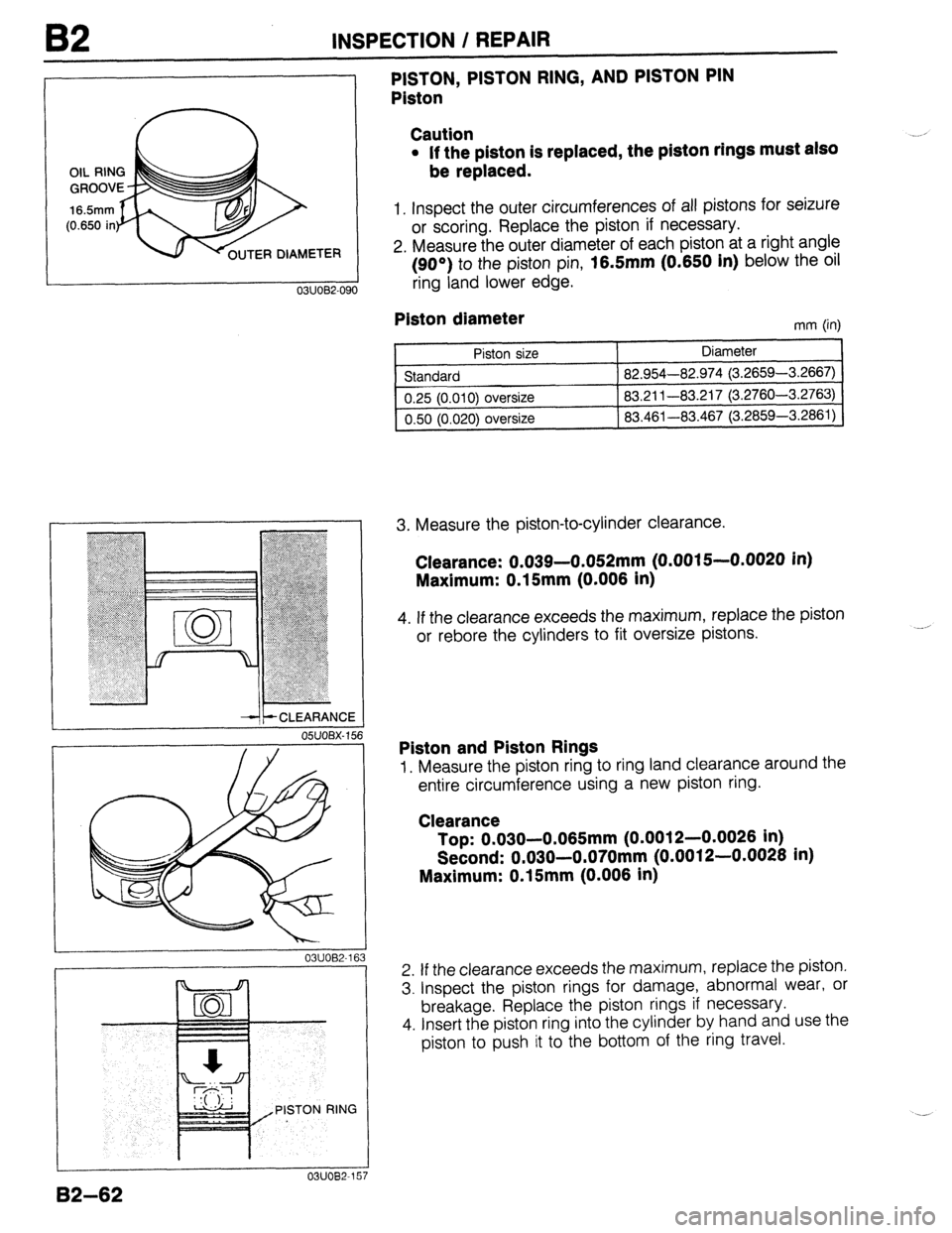
1. Inspect the outer circumferences of all pistons for seizure
or scoring. Replace the piston if necessary.
2. Measure the outer diameter of each piston at a right angle
(90°) to the piston pin,
16.5mm (0.650 In) below the oil
ring land lower cage.
--It- CLEARANCE
OSUOBX- 156
03UOB2-16 3
PISTON RING
7
PISTON, PISTON RING, AND PISTON PIN
Piston
Plston diameter
mm (in)
Piston size
Standard
0.25 (0.010) oversize
0.50 (0.020)
oversize Diameter
82.954-82.974 (3.2659-3.2667)
83.211-83.217 (3.2760-3.2763)
83.461-83.467 (3.2859-3.2861)
3. Measure the piston-to-cylinder clearance.
Clearance: 0.039-0.052mm (0.0015--0.0020 in)
Maxlmum: 0.15mm (0.006 In)
4. If the clearance exceeds the maximum, replace the piston
or rebore the cylinders to fit oversize pistons.
Piston and Piston Rings
1. Measure the piston ring to ring land clearance around the
entire circumference using a new piston ring.
Clearance
Top: 0.030-0.065mm (0.0012-0.0026 in)
Second: 0.030-0.070mm (0.0012-0.0026 in)
Maximum: 0.15mm (0.006 in)
2. If the clearance exceeds the maximum, replace the piston.
3. Inspect the piston rings for damage, abnormal wear, or
breakage. Replace the piston rings if necessary.
4. Insert the piston ring into the cylinder by hand and use the
piston to push it to the bottom of the ring travel.
B2-62
Page 195 of 1164
INSPECTION / REPAIR 82
05UOBX-160
i OBX-162
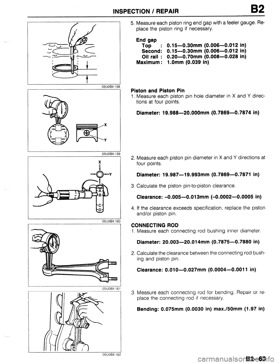
5. Measure each piston ring end gap with a feeler gauge. Re-
place the piston ring if necessary.
End gap
Top : 0.15-0.30mm (0.006-0.012 in)
Second: 0.15-0.30mm (0.006-0.012 in)
Oil rail : 0.20-0.70mm (0.006-0.026 in)
Maximum : l.Omm (0.039 in)
Piston and Piston Pin
1. Measure each piston pin hole diameter in X and Y direc-
tions at four points.
Diameter: 19.968-20.000mm (0.7869-0.7874 in)
2. Measure each piston pin diameter in X and Y directions at
four points.
Diameter: 19.987-19.993mm (0.7869-0.7871 in)
3. Calculate the piston pin-to-piston clearance.
Clearance: -0.005-0.013mm (-0.0002-0.0005 in)
4. If the clearance exceeds specification, replace the piston
and/or piston pin.
CONNECTING ROD
1. Measure each connecting rod bushing inner diameter.
Diameter: 20.003-20.014mm (0.7875-0.7880 in)
2. Calculate the clearance between the connecting rod bush-
ing and piston pin.
Clearance: O.OlO-0.027mm (0.0004-0.0011 in)
3. Measure each connecting rod for bending. Repair or re-
place the connecting rod if necessary.
Bending: 0.075mm (0.0030 in) max./fiOmm (1.97 in)
82-63
Page 196 of 1164
OSUOBX-1E
X
a3 Y
03UOB2-11
CRANKPIN
MAIN JOURNAL
OSUOBX-1
B2 INSPECTION / REPAIR
CRANKSHAFT
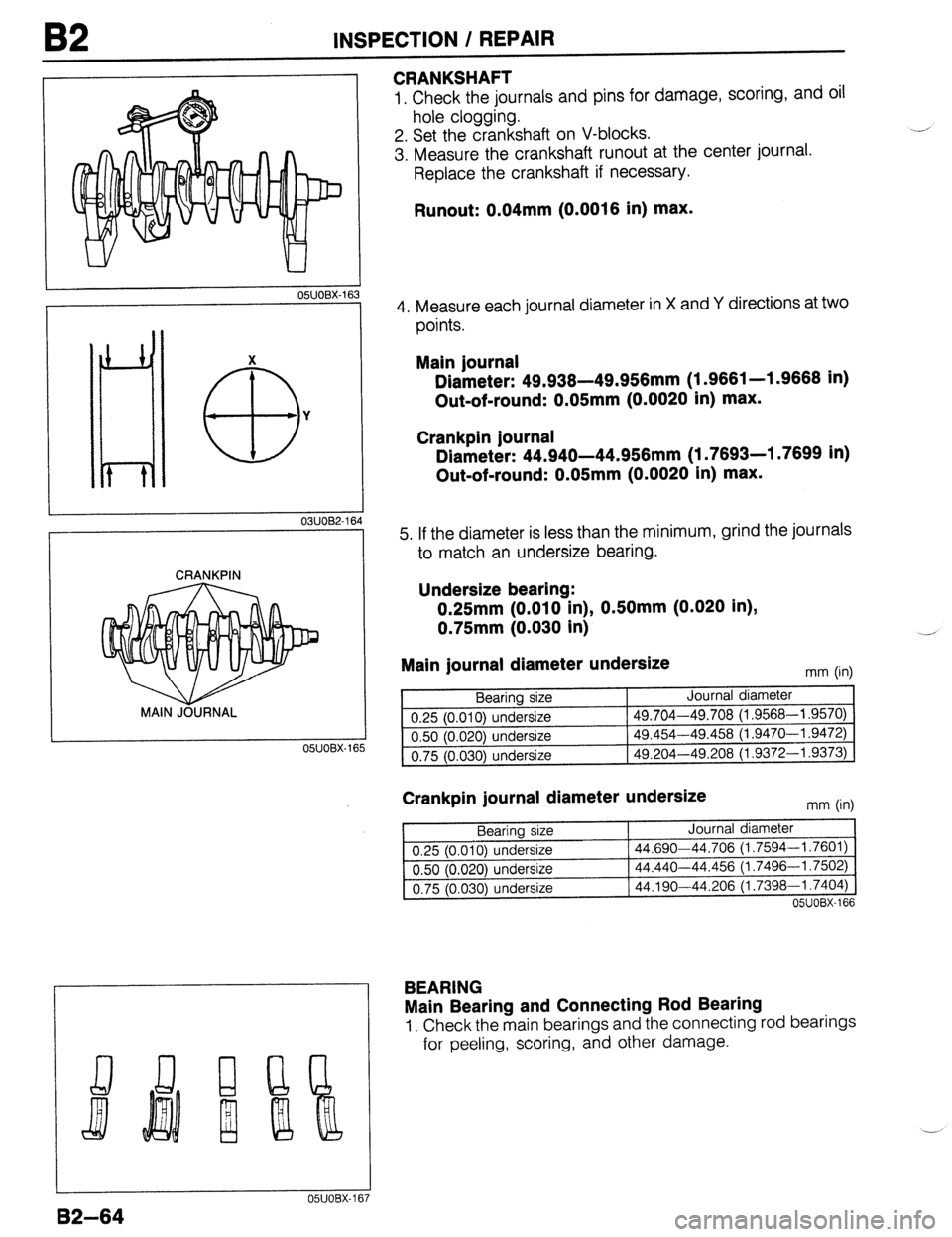
1. Check the journals and pins for damage, scoring, and oil
hole clogging.
2. Set the crankshaft on V-blocks.
3. Measure the crankshaft runout at the center journal.
Replace the crankshaft if necessary.
Runout: 0.04mm (0.0016 in) max.
4. Measure each journal diameter in X and Y directions at two
points.
Main journal
Diameter: 49.938-49.956mm (1.9661-l .9668 in)
Out-of-round: 0.05mm (0.0020 in) max.
Crankpin journal
Diameter: 44.940-44.956mm (1.7693-l .7699 in)
Out-of-round: 0.05mm (0.0020 in) max.
5. If the diameter is less than the minimum, grind the journals
to match an undersize bearing.
Undersize bearing:
0.25mm (0.010 in), OSOmm (0.020 in),
0.75mm (0.030 in)
Main journal diameter undersize
mm (in)
Bearing size Journal diameter
0.25 (0.010) undersize 49.704-49.708 (1.9568-l
.9570)
0.50 (0.020) undersize
49.454-49.458 (1.9470-l .9472)
0.75 (0.030) undersize 49.204-49.208
(1.9372-l .9373)
Crankpin journal diameter undersize mm (in)
Bearing size Journal diameter
0.25 (0.010) undersize 44.690-44.706
(1.7594-l .7601)
0.50 (0.020) undersize 44.440-44.456 (1.7496-l
.7502)
0.75 (0.030) undersize
44.190-44.206 (1.7398-l .7404)
05UOBX-166
BEARING
Main Bearing and Connecting Rod Bearing
1. Check the main bearings and the connecting rod bearings
for peeling, scoring, and other damage.
05UOBX-167
B2-64
Page 197 of 1164
INSPECTION / REPAIR B2
25mm (1 .O in) MIN.
05UOEX-16;
DAMAGE,
WEAR
05UOBX-16
1
s
9
OWOBX-170
O-WOBX-171 .___--__-____--
OSUOBX-172
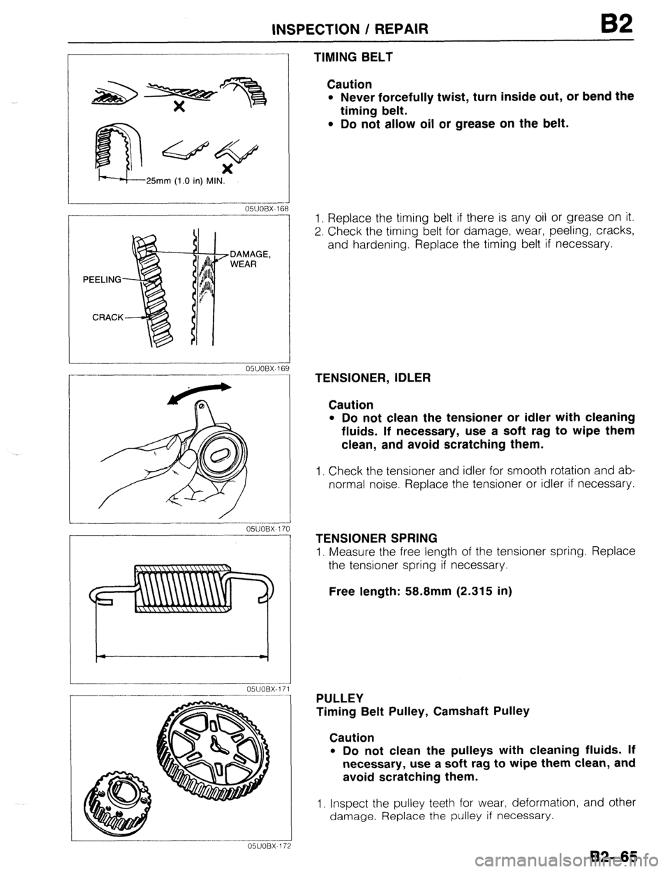
TIMING BELT
Caution
l Never forcefully twist, turn inside out, or bend the
timing belt.
l Do not allow oil or grease on the belt.
1. Replace the timing belt if there is any oil or grease on it.
2. Check the timing belt for damage, wear, peeling, cracks,
and hardening. Replace the timing belt if necessary.
TENSIONER, IDLER
Caution
l Do not clean the tensioner or idler with cleaning
fluids. If necessary, use a soft rag to wipe them
clean, and avoid scratching them.
1. Check the tensioner and idler for smooth rotation and ab-
normal noise. Replace the tensioner or idler if necessary.
TENSIONER SPRING
1. Measure the free length of the tensioner spring. Replace
the tensioner spring if necessary.
Free length: 58.8mm (2.315 in)
PULLEY
Timing Belt Pulley, Camshaft Pulley
Caution
l Do not clean the pulleys with cleaning fluids. If
necessary, use a soft rag to wipe them clean, and
avoid scratching them.
1. Inspect the pulley teeth for wear, deformation, and other
damage. Replace the pulley if necessary.
B2-65
Page 198 of 1164
B2
ASSEMBLY
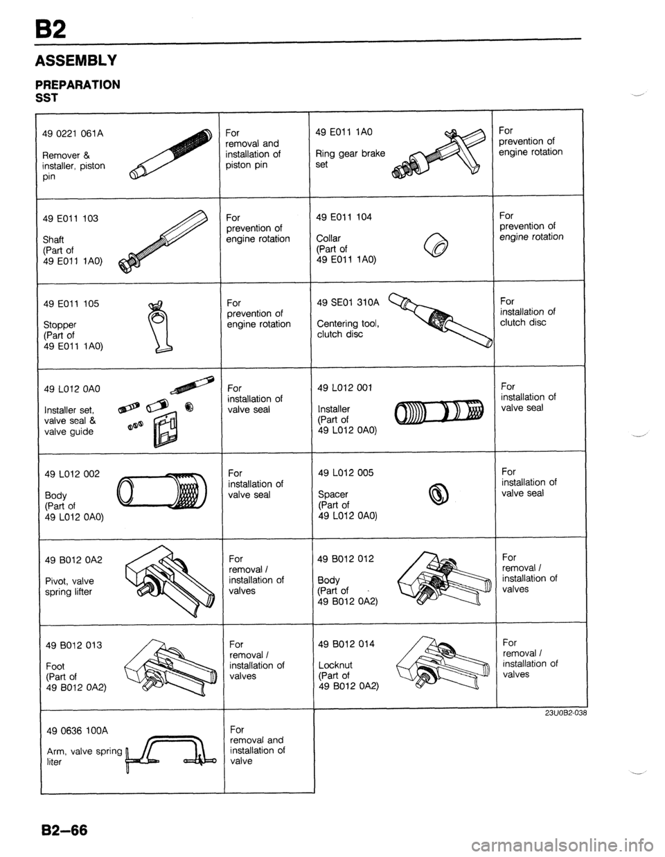
PREPARATION
SST
For
xevention of
sngine rotation For
removal and
installation of
piston pin 49 EOII IA0
Ring gear brake
set 49 0221 061A
Remover &
installer, piston
pin
For
prevention of
engine rotation For
prevention of
engine rotation 49 EOll 104
Collar
(Part of
49 EOl 1 1 AO) 49 E011 103
Shaft
(Part of
49 E011 iA0)
For
installation of
clutch disc For
prevention of
engine rotation 49 EOll 105 49 EOll 105
49 SE01 310A
Centering tool,
clutch disc Stopper Stopper
(Part of (Part of
49 EOI 1 1 AO) 49 EOI 1 1 AO)
49 LO12 OAO
For
nstallation of
valve seal For
installation of
valve seal 49 LO12 001
Installer set, @@ @
valve seal &
valve guide a@ Installer
(Part of
49 LO12 OAO)
49 LO12 005
Spacer
(Part of
49 LO12 OAO) For
installation of
valve seal For
installation of
valve seal 49 LO12 002
Body
(Part of
b9 LO12 OAO)
For
removal I
installation of
valves 49 B012 012
Body
(Part of
49 9012 OA2) For
removal /
installation of
valves 49 8012 OA2
Pivot, valve
spring lifter
For
removal I
‘nstallation of
valves For
removal I
installation of
valves 49 B012 014
-ocknut
:Part of
49 B012 OA2) 49 8012 013
Foot
(Part of
49 8012 OA2)
23UOEi2-0:
For
removal and
installation of
valve 49 0636 IOOA
Arm, valve spring
liter
82-66
Page 199 of 1164
ASSEMBLY B2
1. Clean all parts before reinstallation.
2. Apply new engine oil to all sliding and rotating parts.
3. Replace plain bearings if they are peeling, burned, or otherwise damaged.
4. Tighten all bolts and nuts to the specified torques.
Caution
l Do not reuse gaskets or oil seals.
93GOBl-082
B2-67
Page 200 of 1164
B2 ASSEMBLY
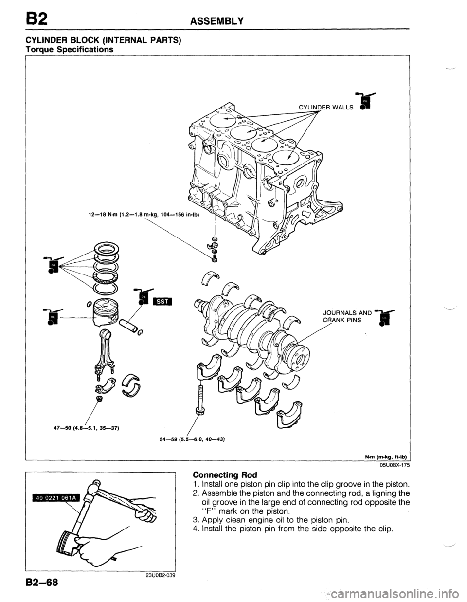
CYLINDER BLOCK (INTERNAL PARTS)
Torque Specifications
12-18 N.m (1.2-1.8
JOURNALS AND
47-50 (4.8--/6.1, 35-37)
N-m (m-kg, ft-lb)
Connecting Rod
o5uoBx-175
1. Install one piston pin clip into the clip groove in the piston.
2. Assemble the piston and the connecting rod, a ligning the
oil groove in the large end of connecting rod opposite the
“F” mark on the piston.
3. Apply clean engine oil to the piston pin.
4. Install the piston pin from the side opposite the clip.
I 23uor32.039
82-68