MITSUBISHI DIAMANTE 1900 Owners Manual
Manufacturer: MITSUBISHI, Model Year: 1900, Model line: DIAMANTE, Model: MITSUBISHI DIAMANTE 1900Pages: 408, PDF Size: 71.03 MB
Page 91 of 408
.
3-30 ENGINEANDENGINEOVERHAUL
23. Using all new gaskets, install the intake man-
ifold, air intake plenum and exhaust manifold.
24. Install the air intake hose.
25. Fill the system with coolant.
26. Connect the negative battery cable.
27. Start the engine.
28. Check and adjust the idle speed and ignition
timing.
29. Once the vehicle has cooled, recheck the
coolant level.
3.51 Engine
ti See Figure 134
1. Disconnect the negative battery cable.
2. Drain the engine coolant
Never open, service or drain the radiator or
cooling system when hot; serious burns can
occur from the steam and hot coolant. Also,
when draining engine coolant, keep in mind
that cats and dogs are attracted to ethylene
glycol antifreeze and could drink any that is
left in an uncovered container or in puddles
on the ground. This will prove fatal in suffi-
cient quantities. Always drain coolant into a
sealable container. Coolant should be reused
unless it is contaminated or is several years
old.
3. Remove the timing belt. Refer to the timing
belt procedure in this section.
4. Remove the intake and exhaust manifolds.
5. Remove the spark plug wires.
6. Remove the cylrnder head covers.
7. Remove the timing belt rear center cover.
8. Loosen the cylinder head bolts gradually in
three stages, in the opposite of the installation se-
quence.
9. Remove the cylinder head.
To install: 10. Clean the cylinder head and mounting sur-’
face on the engine block.
11. Install the cylinder head using a new gasket.
12. Tighten the bolts in sequence using three
stages to 76-83 ft. Ibs. (103-113 Nm).
13. Install the timing belt rear center cover.
14. Install the cylinder head covers using new
gaskets. Tighten the bolts to 2-3 ft. Ibs. (334 Nm).
15. Install the spark plug wires,
16. Install the intake and exhaust manifolds,
17. Install the timing belt. Refer to the timing belt
procedure in this section.
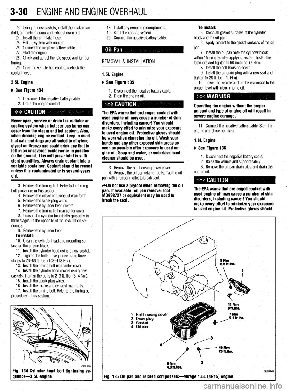
7923PGD2 Fig. 134 Cylinder head bolt tightening se-
quence-3.5L engine
18. Install any remaining components.
19. Refill the cooling system.
20. Connect the negative battery cable.
REMOVAL &INSTALLATION
1.5L Engine
p See Figure 135
1. Disconnect the negative battery cable.
2. Drain the engine oil.
The EPA warns that prolonged contact with
used engine oil may cause a number of skin
disorders, including cancer! You should
make every effort to minimize your exposure
to used engine oil. Protective gloves should
be worn when changing the oil. Wash your
hands and any other exposed skin areas as
soon as possible after exposure to used en-
gine oil. Soap and water, or waterless hand
cleaner should be used.
3. Remove the bell housing lower cover.
4. Remove the oil pan retainer bolts. Tap the oil
pan with a rubber mallet to break seal.
*Do not use a prytool when removing the oil
pan. If available, oil pan remover tool
MD998727 or equivalent may be used to
break the seal. To install:
5. Clean all gasket surfaces of the cylinder
block and the oil pan.
6. Apply sealant to the gasket surfaces of the oil
pan.
7. Install the oil pan onto the cylinder block
within 15 minutes after applying sealant. Install the
fasteners and tighten to 60 inch Ibs. (7 Nm).
8. Install the bell housing cover.
9. Install the oil drain plug with a new seal and
tighten to 29 ft. Ibs. (40 Nm).
10. Lower the vehicle and fill the crankcase to the
proper level with clean engine oil.
Operating the engine without the proper
amount and type of engine oil will result in
severe engine damage.
11. Connect the negative battery cable. Start the
engine and check for leaks.
1.8L Engine
# See Figure 136
1. Disconnect the negative battery cable.
2. Raise the vehicle and support safely.
3. Remove the oil pan drain plug and drain the
engine oil.
The EPA warns that prolonged contact with
used engine oil may cause a number of skin
disorders, including cancer! You should
make every effort to minimize your exposure
to used engine oil. Protective gloves should
I Fig. 135 Oil pan and related components-Mirage 1.5L (4615) engine
Page 92 of 408
ENGINEANDENGINEOVERHAUL 3-31
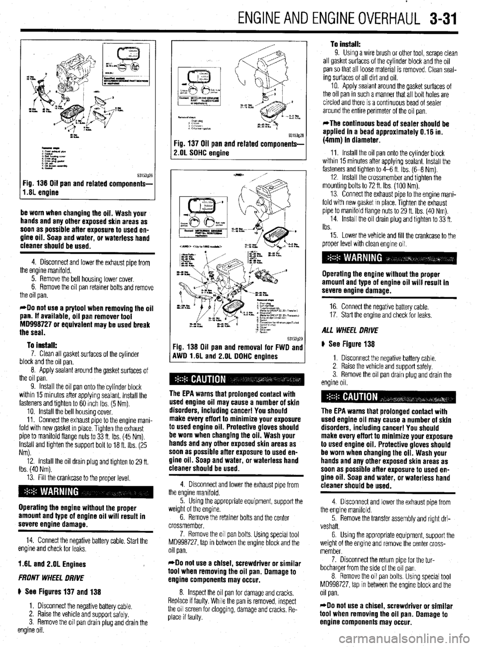
I,.s; engine g3i53g26
Fig 136 Oil pan and related components-
be worn when changing the oil. Wash your
hands and any other exposed skin areas as
soon as possible after exposure to used en-
gine oil. Soap and water, or waterless hand
cleaner should be used.
4. Disconnect and lower the exhaust pipe from
the engine manifold.
5. Remove the bell housing lower cover.
6. Remove the oil pan retainer bolts and remove
the oil pan.
*Do not use a prytool when removing the oil
pan. If available, oil pan remover tool
MD998727 or equivalent may be used break
the seal.
To install:
7. Clean all gasket surfaces of the cylinder
block and the oil pan.
8. Apply sealant around the gasket surfaces of
the oil pan.
9. Install the oil pan onto the cylinder block
within 15 minutes after applying sealant. Install the
fasteners and tighten to 60 inch Ibs. (5 Nm).
10. install the bell housing cover.
11. Connect the exhaust pipe to the engine mani-
fold with new gasket in place. Tighten the exhaust
pipe to manifold flange nuts to 33 ft. Ibs. (45 Nm).
Install and tighten the support bolt to 18 ft. Ibs. (25
Nm).
12. Install the oil drain plug and tighten to 29 ft.
Ibs. (40 Nm).
13. Fill the crankcase to the proper level.
Operating the engine without the proper
amount and type of engine oil will result in
severe engine damage.
14. Connect the negative battery cable. Start the
engine and check for leaks.
1.6L and 2.OL Engines
FRONT WHEEL DRIVE
ti See Figures 137 and 138
1. Disconnect the negative battery cable.
2. Raise the vehicle and support safely.
3. Remove the oil pan drain plug and drain the
engine oil.
93153gza Fig. 137 Oil pan and related components-
2.OL SOHC engine
93153g29 Fig. 138 Oil pan and removal for FWD and
AWD l.liL and 2.OL DDHC enoines
The EPA warns that prolonged contact with
used engine oil may cause a number of skin
disorders, including cancer! You should
make every effort to minimize your exposure
to used engine oil. Protective gloves should
be worn when changing the oil. Wash your
hands and any other exposed skin areas as
soon as possible after exposure to used en-
gine oil. Soap and water, or waterless hand
cleaner should be used.
4. Disconnect and lower the exhaust pipe from
the engine manifold.
5. Using the appropriate equipment, support the
weight of the engine.
6. Remove the retainer bolts and the center
crossmember,
7. Remove the oil pan bolts. Using special tool
MD998727, tap in between the engine block and the
oil pan.
*Do not use a chisel, screwdriver or similar
tool when removing the oil pan. Damage to
engine components may occur.
8. Inspect the oil pan for damage and cracks.
Replace if faulty. While the pan is removed, inspect
the oil screen for clogging, damage and cracks. Re-
place if faulty.
To install: 9. Using a wire brush or other tool, scrape clean
all gasket surfaces of the cylinder block and the oil
pan so that all loose material is removed. Clean seal-
ing surfaces of all dirt and oil.
10. Apply sealant around the gasket surfaces of
the oil pan in such a manner that all bolt holes are
circled and there is a continuous bead of sealer
around the entire perimeter of the oil pan.
*The continuous bead of sealer should be
applied in a bead approximately 0.16 in.
(4mm) in diameter.
11. Install the oil pan onto the cylinder block
within 15 minutes after applying sealant. Install the
fasteners and tighten to 4-6 ft. Ibs. (G8 Nm).
12. Install the crossmember and tighten the
mounting bolts to 72 ft. Ibs. (100 Nm).
13. Connect the exhaust pipe to the engine mani-
fold with new gasket In place. Tighten the exhaust
pipe to manifold flange nuts to 29 ft. Ibs. (40 Nm)
14. Install the oil drain plug and tighten to 33 ft.
Ibs.
15. Lower the vehicle and fill the crankcase to the
proper level with clean engine oil.
Operating the engine without the proper
amount and type of engine oil will result in
severe engine damage.
16. Connect the negative battery cable.
17. Start the engine and check for leaks.
ALL WHEEL DRIVE
ti See Figure 138
1. Disconnect the negative battery cable.
2. Raise the vehicle and support safely.
3. Remove the oil pan drain plug and drain the
engine oil.
The EPA warns that prolonged contact with
used engine oil may cause a number of skin
disorders, including cancer! You should
make every effort to minimize your exposure
to used engine oil. Protective gloves should
be worn when changing the oil. Wash your
hands and any other exposed skin areas as
soon as possible after exposure to used en-
gine oil. Soap and water, or waterless hand
cleaner should be used.
4. Disconnect and lower the exhaust pipe from
the engine manifold.
5. Remove the transfer assembly and right dri-
veshaft.
6. Using the appropriate equipment, support the
weight of the engine and remove the center cross-
member.
7. Disconnect the return pipe for the tur-
bocharger from the side of the oil pan.
8. Remove the oil pan bolts. Using special tool
MD998727, tap In between the engine block and the
oil pan.
*Do not use a chisel, screwdriver or similar
tool when removing the oil pan. Damage to
engine components may occur.
Page 93 of 408
.
3-32 ENGINEANDENGINEOVERHAUL
9. Inspect the oil pan for damage and cracks.
Replace if faulty, While the pan is removed, inspect
the oil screen for clogging, damage and cracks, Re-
place if faulty.
To install: 10. Using a wire brush or other tool, scrape clean
all gasket surfaces of the cylinder block and the oil
pan so that all loose material is removed. Clean seal-
ing surfaces of all dirt and oil.
11, Apply sealant around the gasket surfaces of
the oil pan in such a manner that all bolt holes are
circled and there is a continuous bead of sealer
around the entire perimeter of the oil pan.
*The continuous bead of sealer should be
applied in a bead approximately 0.16 in.
(4mm) in diameter.
12. Install the oil pan onto the cylinder block
within 15 minutes after applying sealant. Install the
fasteners and tighten to 4-6 ft. Ibs. (68 Nm).
13. Install the oil return pipe using a new gasket,
if removed. Tighten retainers to 5-7 ft. Ibs. (7-10
Nm).
14. Install the left member and tighten the forward
retainer bolts to 72 ft. Ibs. (100 Nm). Tighten the
rearward left member bolts to 58 ft. Ibs. (80 Nm).
15. Install the transfer assembly and right drive-
shaft.
16. Connect the exhaust pipe from the engine
manifold with new gasket in place. Tighten the ex-
haust pipe to manifold flange nuts to 29 ft. Ibs. (40
Nm).
17. Install the oil drain plug and tighten to 33 ft.
Ibs.
18. Lower the vehicle and fill the crankcase to the
proper level with clean engine oil.
Operating the engine without the proper
amount and type of engine oil will result in
severe enaine damage.
19. Connect the negative battery cable. Start the
engine and check for leaks.
2.4L Engine
) See Figure 139
1, Disconnect the negative battery cable. -
,(L.. K%
2 mM_
-Ip
t 8*t.almcwr
:y&pn
::Elm
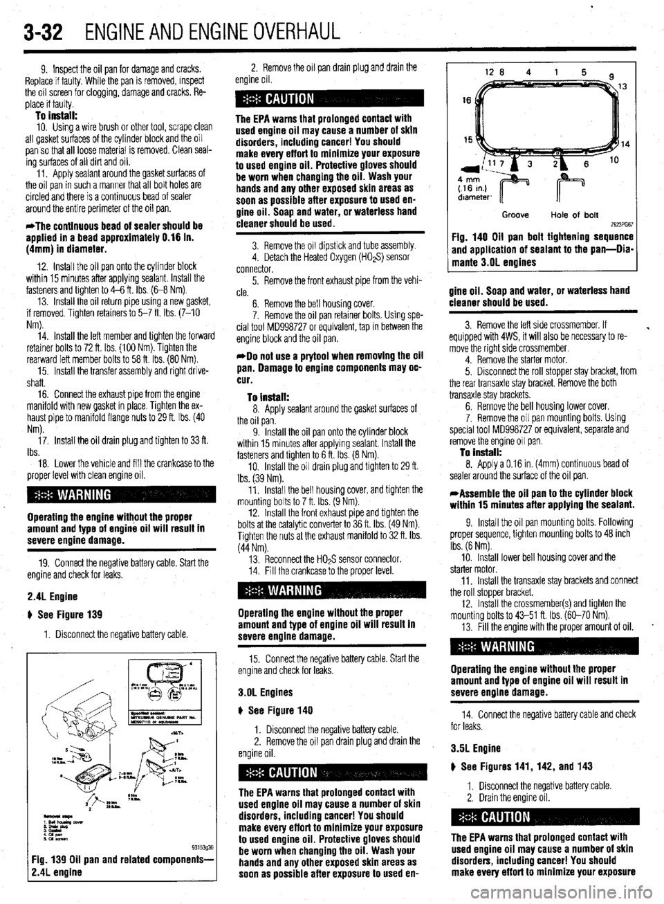
93153g30 Fig. 139 Oil pan and related components-
2.4L engine
2. Remove the oil pan drain plug and drain the
engine oil.
The EPA warns that prolonged contact with
used engine oil may cause a number of skin
disorders, including cancer! You should
make every effort to minimize your exposure
to used engine oil. Protective gloves should
be worn when changing the oil. Wash your
hands and any other exposed skin areas as
soon as possible after exposure to used en-
gine oil. Soap and water, or waterless hand
cleaner should be used.
3. Remove the oil dipstick and tube assembly.
4. Detach the Heated Oxygen (HOaS) sensor
connector.
5. Remove the front exhaust pipe from the vehi-
cle.
6. Remove the bell housing cover.
7. Remove the oil pan retainer bolts. Using spe-
cial tool MD998727 or equivalent, tap in between the
engine block and the oil pan.
*Do not use a prytool when removing the oil
pan. Damage to engine components may oc-
cur.
To install:
8. Apply sealant around the gasket surfaces of
the oil pan.
9. Install the oil pan onto the cylinder block
within 15 minutes after applying sealant. Install the
fasteners and tighten to 6 ft. Ibs. (8 Nm).
10. Install the oil drain plug and tighten to 29 ft.
Ibs. (39 Nm).
11. Install the bell housing cover, and tighten the
mounting bolts to 7 ft. Ibs. (9 Nm).
12. Install the front exhaust pipe and tighten the
bolts at the catalytic converter to 36 ft. Ibs. (49 Nm).
Tighten the nuts at the exhaust manifold to 32 ft. Ibs.
(44 Nm).
13. Reconnect the HOPS sensor connector.
Operating the engine without the proper
amount and type of engine oil will result in
severe engine damage.
15. Connect the negative battery cable. Start the
engine and check for leaks.
3.OL Engines
u See Figure 140
1. Disconnect the negative battery cable.
2. Remove the oil pan drain plug and drain the
The EPA warns that prolonged contact with
used engine oil may cause a number of skin
disorders, including cancer! You should
make every effort to minimize your exposure
to used engine oil. Protective gloves should
be worn when changing the oil. Wash your
hands and any other exposed skin areas as
soon as possible after exposure to used en-
Groove
Hole of bolt 7923PG67 Fig. 140 Oil pan bolt tightening sequence
and application of sealant to the pan-Dia-
mante 3.OL engines
gine oil. Soap and water, or waterless hand
cleaner should be used.
3. Remove the left side crossmember. If
equipped with 4WS, it will also be necessary to re-
move the right side crossmember.
4. Remove the starter motor.
5. Disconnect the roll stopper stay bracket, from
the rear transaxle stay bracket. Remove the both
transaxle stay brackets.
6. Remove the bell housing lower cover.
7. Remove the oil pan mounting bolts. Using
special tool MD998727 or equivalent, separate and
remove the engine oil pan.
To install: 8. Apply a 0.16 in. (4mm) continuous bead of
sealer around the surface of the oil pan.
*Assemble the oil pan to the cylinder block
within 15 minutes after applying the sealant.
9. Install the oil pan mounting bolts. Following
proper sequence, tighten mounting bolts to 48 inch
Ibs. (6 Nm).
10. Install lower bell housing cover and the
starter motor.
11, Install the transaxle stay brackets and connect
the roll stopper bracket.
12. Install the crossmember and tighten the
mounting bolts to 43-51 ft. Ibs. (60-70 Nm).
13. Fill the engine with the proper amount of oil.
.
Operating the engine without the proper
amount and type of engine oil will result in
severe engine damage.
14. Connect the negative battery cable and check
for leaks.
3.5L Engine
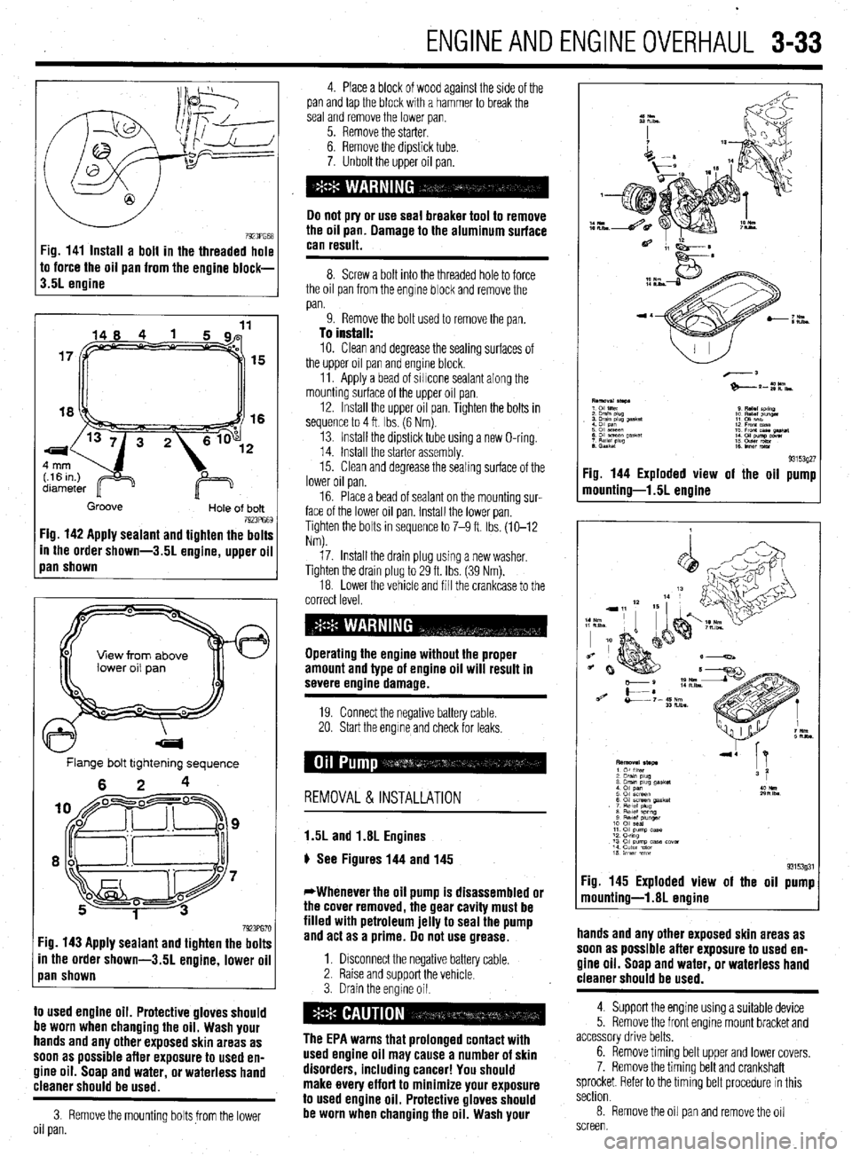
p See Figures 141, 142, and 143
1, Disconnect the negative battery cable.
2. Drain the engine oil.
The EPA warns that prolonged contact with
used engine oil may cause a number of skin
disorders, includina cancer! You should
make eve’ry effort to minimize your exposure
Page 94 of 408
ENGINEANDENGINEOVERHAUL 3-33
7923PG68 Fig. 141 Install a bolt in the threaded hole
to force the oil pan from the engine block-
3.5L engine
15
16
Groove
Hole of bolt 7923PG69 Fig. 142 Apply sealant and tighten the bolts
In the order shown-3.51 engine, upper oil
Ian shown
View from above
Flange bolt tightening sequence
6 2 4
7923PG70 :ig. 143 Apply sealant and tighten the bolts
in the order shown-3.51 engine, lower oil
pan shown
to used engine oil. Protective gloves should
be worn when changing the oil. Wash your
hands and any other exposed skin areas as
soon as possible after exposure to used en-
gine oil. Soap and water, or waterless hand
cleaner should be used.
3. Remove the mounting boltsfrom the lower
oil pan. 4. Place a block of wood against the side of the
pan and tap the block with a hammer to break the
seal and remove the lower pan.
5. Remove the starter.
6. Remove the dipstick tube.
7. Unbolt the upper oil pan.
Do not pry or use seal breaker tool to remove
the oil pan. Damage to the aluminum surface
can result.
8. Screw a bolt into the threaded hole to force
the oil pan from the engine block and remove the
pan.
9. Remove the bolt used to remove the pan.
To install:
10. Clean and degrease the sealing surfaces of
the upper oil pan and engine block.
11. Apply a bead of sillcone sealant along the
mounting surface of the upper oil pan.
12. Install the upper oil pan. Tighten the bolts in
sequence to 4 ft Ibs. (6 Nm).
13. Install the dipstick tube using a new O-ring.
14. Install the starter assembly.
15. Clean and degrease the sealing surface of the
lower oil pan.
16. Place a bead of sealant on the mounting sur-
face of the lower
oil pan. Install the lower pan.
Tighten the bolts in sequence to 7-9 ft. Ibs. (10-12
Nm).
17. Install the drain plug using a new washer,
Tighten the drain plug to 29 ft. Ibs (39 Nm).
18. Lower the vehicle and fill the crankcase to the
correct level.
Operating the engine without the proper
amount and type of engine oil will result in
severe engine damage.
19 Connect the negative battery cable.
20. Start the engrne and check for leaks,
REMOVAL & INSTALLATION
1.5L and 1.8L Engines
p See Figures 144 and 145
*Whenever the oil pump is disassembled or
the cover removed, the gear cavity must be
filled with petroleum jelly to seal the pump
and act as a prime. Do not use grease.
1. Drsconnect the negative battery cable.
2. Raise and support the vehicle.
3. Drain the engine oil.
The EPA warns that prolonged contact with
used engine oil may cause a number of skin
disorders, including cancer! You should
make every effort to minimize your exposure
to used engine oil. Protective gloves should
be worn when changing the oil. Wash your
93153927 Fig. 144 Exploded view of the oil pump
mounting-l .5L engine
93153931 Fig. 145 Exploded view of the oil pump
mounting-l.81 engine
hands and any other exposed skin areas as
soon as possible after exposure to used en-
gine oil. Soap and water, or waterless hand
. . . .
cleaner snoutd be used.
4. Support the engine using a suitable device
5. Remove the front engme mount bracket and
accessory drive belts.
6. Remove timing belt upper and lower covers.
7. Remove the timing belt and crankshaft
sprocket. Refer to the timing belt procedure in this
section.
8. Remove the oil pan and remove the oil
screen.
Page 95 of 408
3-34 ENGINEANDENGINEOVERHAUL
9. Remove the front cover mounting bolts. Note
the lengths of the mounting bolts as they are re-
moved for proper installation.
10. Remove the front case assembly and oil
pump assembly.
11. Remove the oil pump cover.
12. Remove the inner and outer gears from the
front case.
To install 13. Remove all gasket material from the mating
surfaces and clean all parts.
14. Thoroughly coat both oil pump gears with
clean engine oil and install them in the correct direc-
tion of rotation.
15. Install the pump cover and tighten the bolts to
84 inch Ibs. (10 Nm).
16. Coat the relief valve and spring with clean en-
gine oil. Install them and tighten the plug to 33 ft.
Ibs. (45 Nm).
17. Install a new front crankshaft seal and coat
the lips of the seal with clean engine oil.
18. Install the front case and oil pump assembly
to the engine block using a new gasket. Tighten the
bolts to loft. Ibs. (14 Nm)
19. Install the oil screen with new gasket. Torque
the screen bolts to 14 ft. Ibs. (19 Nm).
20. Install the oil pan.
21. Install the crankshaft sprocket and timing
belt. Refer to the timing belt procedure in this sec-
tion.
22. Fill the crankcase to the proper level.
Operating the engine without the proper
amount and type of engine oil will result in
severe enoine damaae.
23. Connect the negative battery cable.
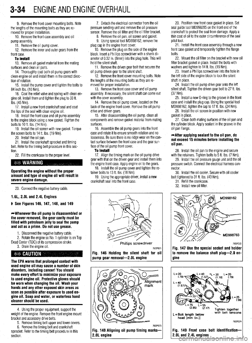
1.6L, 2.OL and 2.4L Engines
p See Figures 146, 147, 148, and 149
*Whenever the oil pump is disassembled or
the cover removed, the gear cavity must be
filled with petroleum jelly to seal the pump
and act as a prime. Do not use grease.
1. Disconnect the negative battery cable.
2. Rotate the engine so No. 1 cylinder is on Top
Dead Center (TDC) of its compression stroke.
3. Drain the engine oil.
The EPA warns that prolonged contact with
used engine oil may cause a number of skin
disorders, including cancer! You should
make every effort to minimize your exposure
to used engine oil. Protective gloves should
be worn when changing the oil. Wash your
hands and any other exposed skin areas as
soon as possible afler exposure to used en-
gine oil. Soap and water, or waterless hand
cleaner should be used.
4 Using the proper equipment, support the
weight of the engine Remove the front engine mount
bracket and accessory drive belts.
5 Remove timing belt upper and lower covers.
6. Remove the timing belt and crankshaft
sprocket. Refer to the timing belt procedure in this
section. 7. Detach the electrical connector from the oil
pressure sending unit and remove the oil pressure
sensor. Remove the oil filter and the oil filter bracket.
8. Remove the oil pan, oil screen and gasket.
9. Using special tool MD998162, remove the
plug cap in the engine front cover.
10. Remove the plug on the side of the engine
block. Insert a Phrllips screwdriver with a shank di-
ameter of 0.32 in. (8mm) into the plug hole. This will
hold the silent shaft.
11. Remove the driven gear bolt that secures the
oil pump driven gear to the silent shaft.
12. Remove the front cover mounting bolts. Note
the lengths of the mounting bolts as they are re-
moved for proper installation.
13. Remove the front case cover and oil pump
assembly. If necessary, the silent shaft can come out
with the cover assembly.
14. Remove the oil pump cover, located on the
back of the engine front cover. Remove the oil pump
drive and driven gears.
15. After disassembling the oil pump, clean all
components and remove gasket material from mating
surfaces.
16. Assemble the oil pump gears into the front
case and rotate it to ensure smooth rotation and no
looseness. Be sure there is no ridge wear on the con-
tact surface between the front case and the gear sur-
face of the oil pump front cover.
To install 17. Align the timing mark on the oil pump drive
gear with that on the driven gear and install them into
the engine front case. Apply engine 011 to the gears.
18. Install the oil pump cover and tighten the re-
tainer bolts to 13 ft. Ibs. (18 Nm).
19. Using the appropriate driver, install a new
crankshaft seal into the front case.
Phrllips screwdrrver
7923PG71 Fig. 146 Holding the silent shaft for oil
pump gear removal-2.01 engine
7923PG73 Fig. 148 Aligning oil pump timing marks-
2.OL ermine
20. Position new front case gasket in place. Set
seal guide tool MD998285 on the front end of the
crankshaft to protect the seal from damage. Apply a
thin coat of oil to the outer circumference of the seal
pilot tool.
21. Install the front case assembly through a new
front case gasket and temporarily tighten the flange
bolts.
22. Mount the oil filter on the bracket with new oil
filter bracket gasket in place. Install the bolts with
washers and tighten to 14 ft. Ibs. (19 Nm).
23. Insert a Phillips screwdriver into the hole in
the left side of the engine block to lock the silent
shaft in place.
24. Install the oil pump drive gear onto the left
silent shaft. Tighten the driven gear bolt to 27 ft. Ibs.
(37 Nm).
25. Install a new O-ring to the groove in the front
case and install the plug cap. Using the special tool
MD998162, tighten the cap to 17 ft. Ibs. (24 Nm).
26. Install the oil screen in position with new
gasket in place.
27. Clean both mating surfaces of the oil pan and
the cylinder block. Apply sealant In the groove in the
oil pan flange.
*After applying sealant to the oil pan, do
not exceed 15 minutes before installing the
oil pan.
28. Install the oil pan to the engine and secure
with the retainers. Tighten bolts to 5 ft. Ibs. (7 Nm).
29. install the oil pressure gauge unit and the oil
pressure switch. Connect the electrical harness con-
nector.
30. Install the oil cooler. Secure with oil cooler
bolt tightened to 31 ft. Ibs (43 Nm).
31. Refill the crankcase.
32. Install new oil filter.
7923PG72 Fig. 147 Use the special socket and holder
:o remove the balance shaft plug-2.0 en-
7ine
L= Bolt length below
head /mm (cn.)]
Fig. 149 Front case bolt identification-
?.OL and 2.4L engines
Page 96 of 408
ENGINEANDENGINEOVERHAUL 3-35
Operating the engine without the proper
amount and type of engine oil will result in
severe engine damage.
33. Connect the negative battery cable and start
the engine.
34. Verify correct oil pressure
35. Inspect for leaks.
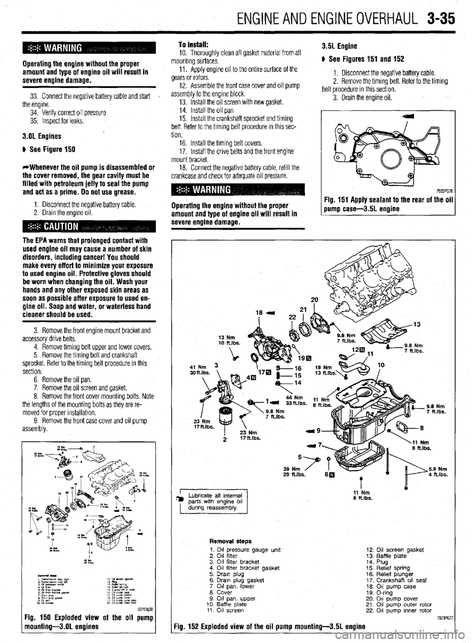
3.OL Engines
b See Figure 150
*Whenever the oil pump is disassembled or
the cover removed, the gear cavity must be
filled with petroleum jelly to seal the pump
and act as a prime. 00 not use grease.
1. Disconnect the negative battery cable.
2. Drain the engine oil.
The EPA warns that prolonged contact with
used engine oil may cause a number of skin
disorders, including cancer! You should
make every effort to minimize your exposure
to used engine oil. Protective gloves should
be worn when changing the oil. Wash your
hands and any other exposed skin areas as
soon as possible after exposure to used en-
gine oil. Soap and water, or waterless hand
cleaner should be used.
3. Remove the front engine mount bracket and
accessory drive belts.
4. Remove timing belt upper and lower covers.
5. Remove the timing belt and crankshaft
sprocket. Refer to the timing belt procedure in this
section.
6 Remove the oil pan.
7. Remove the oil screen and gasket.
8. Remove the front cover mounting bolts. Note
the lengths of the mounting bolts as they are re-
moved for proper installation.
9. Remove the front
assembly. and oil pump
9315393i 7g. 150 Exploded view of the oil pump
nounting-3.01 engines
To install:
10. Thoroughly clean all gasket material from all
mounting surfaces.
11. Apply engine oil to the entire surface of the
gears or rotors.
12. Assemble the front case cover and oil pump
assembly to the engine block.
13. Install the oil screen with new gasket.
14. Install the oil pan
15. Install the crankshaft sprocket and timing
belt. Refer to the timing belt procedure in this sec-
tion 3.5L Engine
p See Figures 151 and 152
1. Disconnect the negative battery cable.
2. Remove the timing belt. Refer to the timing
belt procedure in this section.
3. Drain the engine oil.
16. Install the timing belt covers.
17. Install the drive belts and the front engine
mount bracket.
18. Connect the negative battery cable, refill the
crankcase and check for adequate oil pressure.
Operating the engine without the proper
amount and type of engine oil will result in
severe engine damage. Fig. 151 Apply sealant to the rear of the oil
pump case-3.5L ermine
I 11 Nm
8 ft.lbs.
Removal steps
7g. 152 Exploded view of the oil pump mounting-3.51 engine
1. 011 pressure gauge unit
2. 011 filter
3. 011 filter bracket
4. 011 filter bracket gasket
5. Drain plug
6. Drawn plug gasket
7 011 lower pan,
8. Cover
9 011 pan, upper
10. Baffle date 11. 011 screen
12.
13.
14.
15.
16.
17.
10.
19.
20.
21.
22. Oil screen gasket
Baffle plate
Plug
Reltef spring
Relief plunger
Crankshaft oil seal
Oil pump case
0-ring
011 pump cover
011 pump outer rotor
011 pump inner rotor
Page 97 of 408
3-36 ENGINEANDENGINEOVERHAUL
The EPA warns that urolonaed contact with
used engine oil may cause”a number of skin
disorders, including cancer! You should
make every effort to minimize your exposure
to
used engine oil. Protective gloves should
be worn when changing the oil. Wash your
hands and any other exposed skin areas as
soon as possible after exposure to
used en-
gine oil. Soap and water, or waterless hand
cleaner should be used.
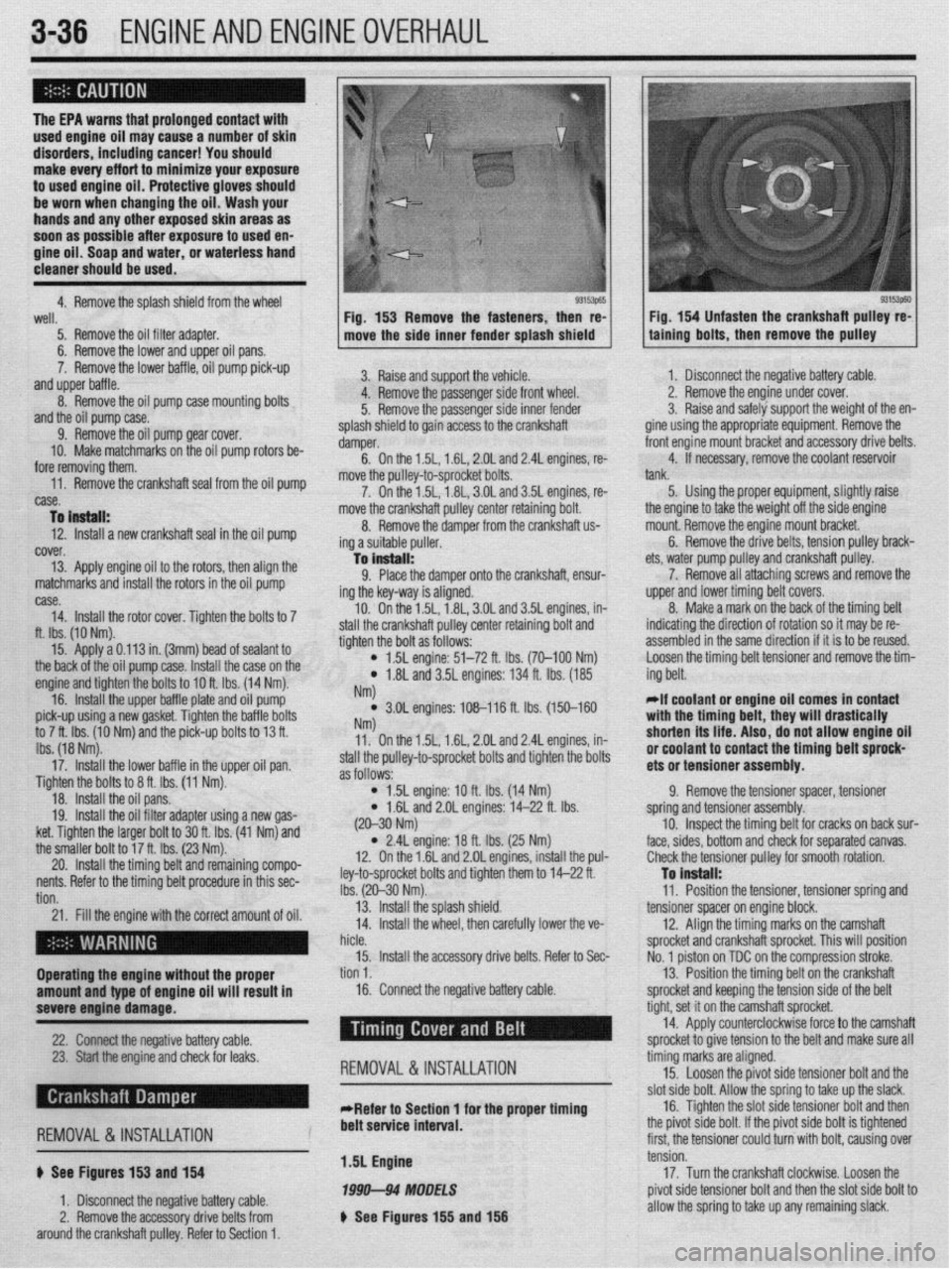
4. Remove the solash shield from the wheel
93153p65 93153p60 well.
5. Remove the oil filter adapter.
6. Remove the lower and upper oil pans.
7. Remove the lower baffle, oil pump pick-up
and upper baffle.
8. Remove the oil pump case mounting bolts
and the oil pump case.
9. Remove the oil pump gear cover.
10. Make matchmarks on the oil pump rotors be-
fore removing them.
,,. r.-- -IL- -.( -L.11---‘I --. IL- -.I _ --
nemove me cranksnarr sear rrom me 011 pump
case.
To instell:
12. Install a new crankshaft seal in the oil pump
cover.
13. Apply engine oil to the rotors, then align the
matchmarks and install the rotors in the oil pump Fig. 153 Remove the fasteners, then re-
move the side inner fender splash shield
3. Raise and support the vehicle.
4. Remove the passenger side front wheel.
5. Remove the passenger side inner fender
splash shield to gain access to the crankshaft
damper.
6. On the 1.5L, 1.6L, 2.OL and 2.4L engines, re-
move the oullev-to-sorocket bolts.
7. On thei .5L, i .8L, 3.OL and 3.5L engines, re-
move the crankshaft pulley center retaining bolt.
8. Remove the damper from the crankshaft us
ing a suitable puller.
-la install:
9. Place the damper onto the crankshaft, ensur-
ing the key-way is aligned.
10. On the 1.5L, 1.8L, 3.OL and 3.5L engines, in-
e crankshaft pulley center retaining bolt and
the bolt as follows: Fig. 154 Unfasten the crankshaft pulley re-
talning bolts, then remove the pulley
case.
14. Install the rotor cover. Tighten the bolts to 7
ft. Ibs. (10 Nm).
15. Apply a 0.113 in. (3mm) bead of sealant to
the back of the oil pump case. I[ -‘-‘I IL -~-- IL-
nsrall me ca
se on me engine and tighten the bolts to IOft Ihc 11 ,,, -. , .4 Nm).
16. Install the upper baffle r tlal te and oil pump
pick-up using a new gasket. Tic fhtti,, ,,lG va,,,ti ““a,., an tha hafflc, hnltc to 7 ft. Ibs. (10 Nm) and the pit k-up bolts to 13 ft.
Ibs. (18 Nm).
17. Install the lower baffle in the upper oil pan.
Tighten the bolts to 8 ft. Ibs. (11 Nm).
18. Install the oil pans.
19. Install the oil filter adapter using a new gas-
ket. Tighten the larger bolt to 30 ft. Ibs. (41 Nm) and
the smaller bolt to 1’ u ‘L- Inn ‘I--’ stall thl
tighten
4
) 1.5L engine: 51-72 ft. Ibs. (70-100 Nm)
l 1.8L and 3.5L engines: 134 ft. Ibs. (185
NM
l 3.OL engines: 108-116 ft. lbs. (150-160 NW 11. On the 1.5L, 1.6L, 2.OL and 2.4L engines, in-
stall the pulley-to-sprocket bolts and tighten the bolts
as follows:
l 1.5L engine: 10 ft. Ibs. (14 Nm)
* 1.6L and 2.OL engines: 14-22 ft. Ibs. 1. Disconnect the negative battery cable.
2. Remove the engine under cover.
3. Raise and safely support the weight of the en-
gine using the appropriate equipment. Remove the
front engine mount bracket and accessory drive belts.
4. If necessary, remove the coolant reservoir
tank.
5. Using the proper equipment, slightly raise
ets, water pump pulley
7. Remove all attr
upper and lower timin{
8. Make a mark o
indicating the directior
assembled in the same the engine to take the weight off the side engine
mount. Remove the engine mount bracket.
6. Remove the drive belts, tension pulley brack-
and crankshaft pulley.
aching screws and remove the
J belt covers.
n the back of the timing belt
I of rotation so it may be re-
! direction if it is to be reused.
tensioner and remove the tim-
Loosen the timing belt
ing belt.
*If coolant or engine oil comes in contact
with the timing bplt thaw will r(mcti~~llv Wll L, .,,s,, n,,, u,uu.,vu,,,
shorten its life. A ,IS o, do not allow engine oil
#.I nn..lr”* In rind In,
“I IruuI(IIIL Lu Irulll&t the timing belt sprock-
ets or tensioner assembly.
9. Remove the tensioner spacer, tensioner
spring and tensioner assembly.
cracks on back sur-
;eoarated canvas.
20. Install the tilllIllY uljllOllu IclllallllllY ~ullIPV-
:
nents. Refer to the timing belt procedure in this sec-
: tion.
21. Fill the engine with the correct amount of oil.
I . (20-30 Nm)
l 2.4L engine: 18 ft. Ibs. (25 Nm)
12. On the 1.6L and 2.OL engines, install the pul-
ley-to-sprocket bolts and tighten them to 14-22 ft.
Ibs. (20-30 Nm).
13. Install the splash shield.
14. Install the wheel, then carefully lower the ve- 10. Inspect the timing belt for I
face, sides, bottom and check for ! (
Check the tensioner pulley for smooth rotation.
To install:
11. Position the tensioner, tensioner spring and
tensioner spacer on engine block.
12. Align the timing marks on the camshaft
ft sprocket. This will position
tn the comoression stroke.
I hicle.
sprocket and cranksha
15. Install the accessory drive belts. Refer to Sec-
No. 1 piston on TDC o
Operating the engine without the proper tion 1.
13. Position the timing belt on the crankshaft
amount and type of engine oil will result in 16. Connect the negative battery cable.
sprocket and keeping the tension side of the bolt
severe engine damage.
-
22. -s
Chrmxt the nenntive h;lttm cnhle --, , I” ,.-J XL.._ I -..-., --I.-.
23. Start the engine and check for leaks.
REMOVAL &INSTALLATION
tight, set it on the cam, shaft sprocket.
14. Apply counterc Yockwise force to the camshaft
snrnckd tn nive tensin In -r .__.._. ._ J..- ._ - _ to the belt and make sure all
timing marks are aligned.
15. Loosen the pivot side tensioner bolt and the
clnt
&In hnlt Allnur thn rnrinn tn tdm III-I thn slack, cl then , d I, I’ r),“I 44”” ““IL. “ll”sl LllU .y”“yj L” L”I\U Low Ul” L .-Refer to Section 1 for the proper timing 16. Tighten the slot side tensioner bolt ark
., , , , ,, ,, ,, , , , , ,, . ,, ,~
REMOVAL &INSTALLATION
6 See Figures 153 and 154
1. Disconnect the negative battery cable.
2. Remove the accessory drive belts from
around the crankshaft pulley. Refer to Section 1. belt service interval.
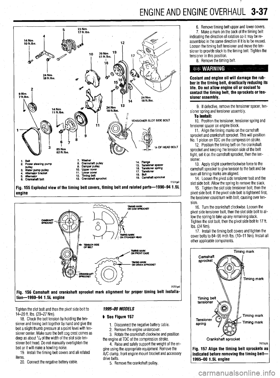
1.5L Engine
1999-94 MODELS
b See Figures 155 and 156 me p~vor sloe DOI~. IT me p~vor sloe OOII
IS ogntened
first, the tensioner could turn with bolt, causing over
tension.
17. Turn the crankshaft clockwise. Loosen the
pivot side tensioner bolt and then the slot side bolt to
allow the spring to take up any remaining slack.
Page 98 of 408
ENGINEANDENGINEOVERHAUL 3-37
1. Ben
2. Power4teerlna Dump 7. washer
8. Crankshaft pullet
9. Damper pulls
10. upper ccwer
11. Lowercowr
12. llmingbeil
13. crsnkshat? E#ocket 14. Flsnge
i 5. Tensbner spacer
16. Tef~kner WkW
1; Tgibnrr
19: camehan sprocket
91251ga
Fig. 155 Exploded view of the timing belt covers, timing belt and related parts-1990-94 1.51
engine
Fig. 156 Camshaft and crankshaft sprocket mark alignment for proper timing belt installa-
tion-1990-94 1.51 engine
Tighten the slot bolt and then the pivot side bolt to
14-20 ft. Ibs. (20-27 Nm).
18. Check the belt tension by holding the ten-
sioner and timing belt together by hand and give the
belt a slight thumb pressure at a point level with ten-
sioner center. Make sure the belt cog crest comes as
deep as about l/4 of the width of the slot side ten-
sioner bolt head. Do not manually overtighten the
belt or it will make a howling noise.
19. Install the timing belt covers and all related
items. 1995-00 MOOFLS
) See Figure 157
1. Disconnect the negative battery cable.
2. Remove the engine undercover.
3. Rotate the crankshaft clockwlse and position
the engine at TDC of the compression stroke.
4. Raise and safely support the weight of the en-
gine using the appropriate equipment. Remove the
A/C clamp, front engine mount bracket and accessory
drive belts.
20. Connect the negative battery cable.
5. Remove the crankshaft pulley. 6. Remove timing belt upper and lower covers.
7. Make a mark on the back of the timing belt
indicating the direction of rotation so it may be re-
assembled in the same direction if it is to be reused.
Loosen the timing belt tensioner and move the ten-
sioner to provide slack to the timing belt. Tighten the
tensioner in this position.
8. Remove the timing belt.
Coolant and engine oil will damage the rub-
ber in the timing belt, drastically reducing its
life. Do not allow engine oil or coolant to
contact the timing belt, the sprockets or ten-
sioner assembly.
9. If defective, remove the tensioner spacer, ten-
sioner spring and tensioner assembly.
To install: 10. Position the tensioner, tensioner spring and
tensioner spacer on engine block.
11. Align the timing marks on the camshaft
sprocket and crankshaft sprocket. This will position
No. 1 piston on TDC on the compression stroke.
12. Position the timing belt on the crankshaft
sprocket and keeping the tension side of the belt
tight, set it on the camshaft sprocket, then the ten-
sioner.
13. Apply slight counterclockwise force to the
camshaft sprocket to give tension to the belt and be
sure all timing marks are aligned.
14. Loosen the pivot side tensioner bolt and the
slot side bolt. Allow the spring to remove the slack.
15. Tighten the slot side tensioner bolt, then the
pivot side bolt. If the pivot side bolt is tightened first,
the tensioner could turn with bolt, causing over ten-
sion.
16. Turn the crankshaft clockwise. Loosen the
pivot side tensioner bolt, then the slot side bolt to al-
low the spring to take up any remaining slack.
Tighten the slot bolt, then the pivot side bolt to 17 ft.
Ibs. (24 Nm).
17. Install the timing belt covers and tighten the
cover bolts to 84-96 inch Ibs. (E-11 Nm). Install all
other applicable components.
liming mark
ming mark
Timing mark
Timing mark
Crankshaft sprocket
79235g5t Fig. 157 Align the timing belt sprockets as
indicated before removing the timing belt-
1995-00 1.51 engine
Page 99 of 408
3-38 ENGINEANDENGINEOVERHAUL
1.61&? 2.OL (Non-Turbo) DOHC Engines
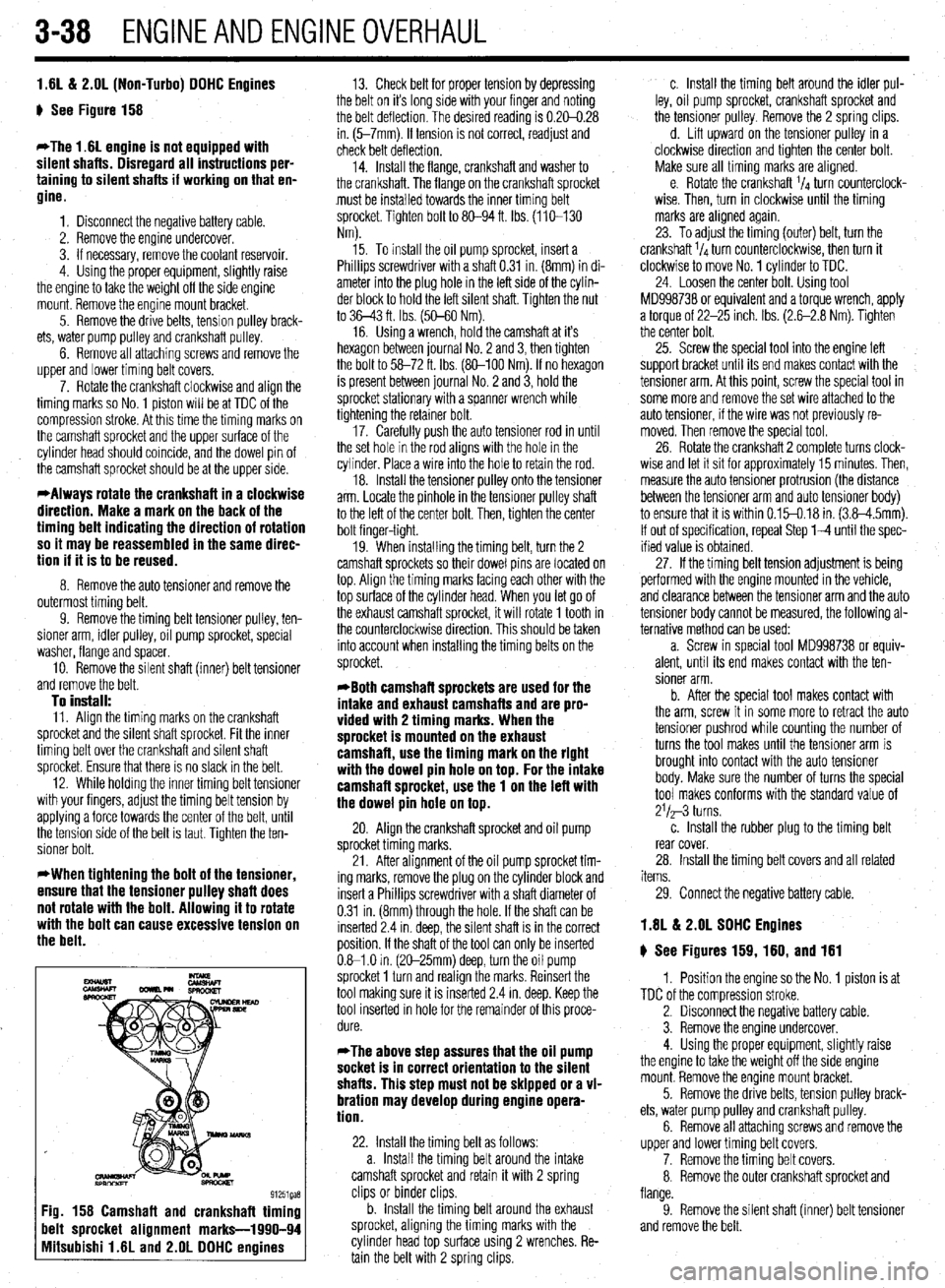
g See Figure 158
*The 1.6L engine is not equipped with
silent shafts. Disregard all instructions per-
taining to silent shafts if working on that en-
gine.
1. Disconnect the negative battery cable.
2. Remove the engine undercover.
3. If necessary, remove the coolant reservoir.
4. Using the proper equipment, slightly raise
the engine to take the weight off the side engine
mount. Remove the engine mount bracket.
5. Remove the drive belts, tension pulley brack-
ets, water pump pulley and crankshaft pulley.
6. Remove all attaching screws and remove the
upper and lower timing belt covers.
7. Rotate the crankshaft clockwise and align the
timing marks so No. 1 piston will be at TDC of the
compression stroke. At this time the timing marks on
the camshaft sprocket and the upper surface of the
cylinder head should coincide, and the dowel pin of
the camshaft sprocket should be at the upper side.
*Always rotate the crankshaft in a clockwise
direction. Make a mark on the back of the
timing belt indicating the direction of rotation
so it may be reassembled in the same direc-
tion if it is to be reused.
8. Remove the auto tensioner and remove the
outermost timing belt.
9. Remove the timing belt tensioner pulley, ten-
sioner arm, idler pulley, oil pump sprocket, special
washer, flange and spacer.
10. Remove the silent shaft (inner) belt tensioner
and remove the belt.
To install: 11. Align the timing marks on the crankshaft
sprocket and the silent shaft sprocket. Fit the inner
timing belt over the crankshaft and silent shaft
sprocket. Ensure that there is no slack in the belt.
12. While holding the inner timing belt tensioner
with your fingers, adjust the timing belt tension by
applying a force towards the center of the belt, until
the tension side of the belt is taut. Tighten the ten-
sioner bolt.
*When tightening the bolt of the tensioner,
ensure that the tensioner pulley shaft does
not rotate with the bolt. Allowing it to rotate
with the bolt can cause excessive tension on
the belt.
13. Check belt for proper tension by depressing
the belt on it’s long side with your finger and noting
the belt deflection. The desired reading is 0.20-0.28
in. (5-7mm). If tension is not correct, readjust and
check belt deflection.
14. Install the flange, crankshaft and washer to
the crankshaft. The flange on the crankshaft sprocket
must be installed towards the inner trming belt
sprocket. Tighten bolt to 80-94 ft. Ibs. (110-130
Nm).
15. To install the oil pump sprocket, insert a
Phillips screwdriver with a shaft 0.31 in. (8mm) in di-
ameter into the plug hole in the left side of the cylin-
der block to hold the left silent shaft. Tighten the nut
to 36-43 ft. Ibs. (50-60 Nm).
16. Using a wrench, hold the camshaft at it’s
hexagon between journal No. 2 and 3, then tighten
the bolt to 58-72 ft. Ibs. (80-100 Nm). If no hexagon
is present between journal No. 2 and 3, hold the
sprocket stationary with a spanner wrench while
tightening the retainer bolt.
17. Carefully push the auto tensioner rod in until
the set hole in the rod aligns with the hole in the
cylinder. Place a wire into the hole to retain the rod.
18. Install the tensioner pulley onto the tensioner
arm. Locate the pinhole in the tensioner pulley shaft
to the left of the center bolt. Then, tighten the center
bolt finger-tight.
19. When installing the timing belt, turn the 2
camshaft sprockets so their dowel pins are located on
top. Align the timing marks facing each other with the
top surface of the cylinder head. When you let go of
the exhaust camshaft sprocket, it will rotate 1 tooth in
the counterclockwise direction. This should be taken
into account when installing the timing belts on the
sprocket.
*Both camshaft sprockets are used for the
intake and exhaust camshafts and are pro-
vided with 2 timing marks. When the
sprocket is mounted on the exhaust
camshaft, use the timing mark on the right
with the dowel pin hole on top. For the intake
camshafl sprocket, use the 1 on the left with
the dowel pin hole on top.
20. Align the crankshaft sprocket and oil pump
sprocket timing marks.
21. After alignment of the oil pump sprocket tim-
ing marks, remove the plug on the cylinder block and
insert a Phillips screwdriver with a shaft diameter of
0.31 in. (8mm) through the hole. If the shaft can be
inserted 2.4 in. deep, the silent shaft is in the correct
position. If the shaft of the tool can only be inserted
0.61 .O in. (2C-25mm) deep, turn the oil pump
sprocket 1 turn and realign the marks. Reinsert the
tool making sure it is inserted 2.4 in. deep. Keep the
tool inserted in hole for the remainder of this proce-
dure.
*The above step assures that the oil pump
socket is in correct orientation to the silent
shafts. This step must not be skipped or a vi-
bration may develop during engine opera-
tion.
22. Install the timing belt as follows:
a. Install the timing belt around the intake
camshaft sprocket and retain it with 2 spring
clips or binder clips.
b. Install the timing belt around the exhaust
sprocket, aligning the timing marks with the
cylinder head top surface using 2 wrenches. Re-
tain the belt with 2 spring clips. c. Install the timing belt around the idler pul-
ley, oil pump sprocket, crankshaft sprocket and
the tensioner pulley. Remove the 2 spring clips.
d. Lift upward on the tensioner pulley in a
clockwise direction and tighten the center bolt.
Make sure all timing marks are aligned.
e. Rotate the crankshaft ‘14 turn counterclock-
wise. Then, turn in clockwise until the timing
marks are alrgned again.
23. To adjust the timing (outer) belt, turn the
crankshaft ‘14 turn counterclockwise, then turn it
clockwise to move No. 1 cylinder to TDC.
24. Loosen the center bolt. Using tool
MD998738 or equivalent and a torque wrench, apply
a torque of 22-25 inch. Ibs. (2.6-2.8 Nm). Tighten
the center bolt.
25. Screw the special tool into the engine left
support bracket until its end makes contact with the
tensioner arm. At this point, screw the special tool in
some more and remove the set wire attached to the
auto tensioner, if the wire was not previously re-
moved. Then remove the specral tool.
26. Rotate the crankshaft 2 complete turns clock-
wise and let it sit for approximately 15 minutes. Then,
measure the auto tensioner protrusion (the distance
between the tensioner arm and auto tensioner body)
to ensure that it is within 0.15-0.18 in. (3.8-4.5mm).
If out of specification, repeat Step l-4 until the spec-
ified value is obtained.
27. If the timing belt tension adjustment is being
performed with the engine mounted in the vehicle,
and clearance between the tensioner arm and the auto
tensioner body cannot be measured, the following al-
ternative method can be used:
a. Screw in special tool MD998738 or equiv-
alent, until its end makes contact with the ten-
sioner arm.
b. After the special tool makes contact with
the arm, screw it in some more to retract the auto
tensioner pushrod while counting the number of
turns the tool makes until the tensioner arm is
brought into contact with the auto tensioner
body. Make sure the number of turns the special
tool makes conforms with the standard value of
21/a-3 turns.
c. Install the rubber plug to the timing belt
rear cover.
28. Install the timing belt covers and all related
items.
29. Connect the negative battery cable.
1.8L & 2.OL SOHC Engines
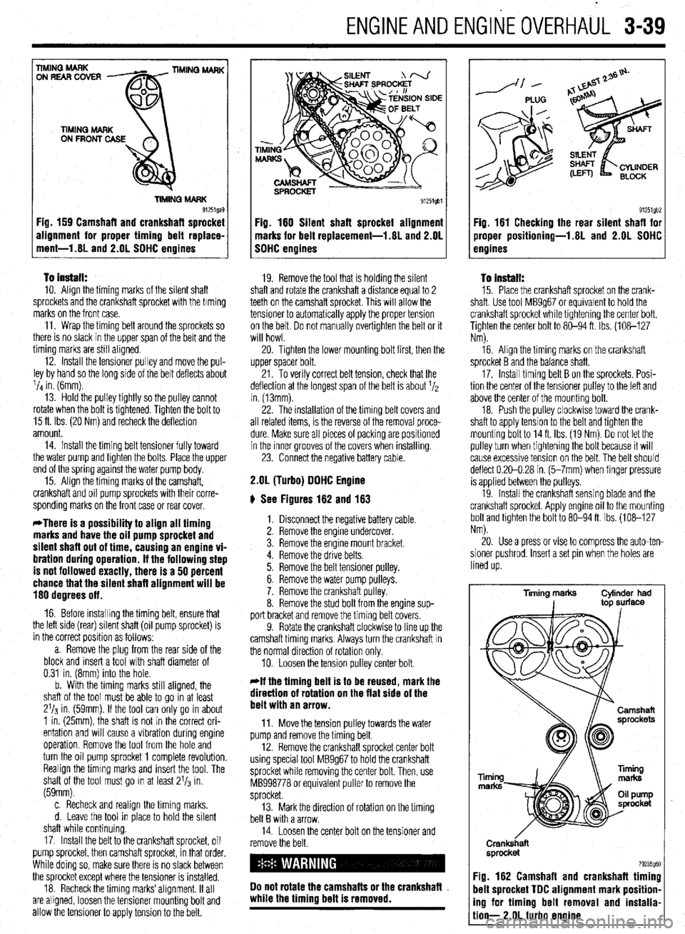
g See Figures 159, 160, and 161
1. Position the engine so the No. 1 piston is at
TDC of the compression stroke.
2. Disconnect the negative battery cable.
3. Remove the engine undercover.
4. Using the proper equipment, slightly raise
the engine to take the weight off the side engine
mount. Remove the engine mount bracket.
5. Remove the drive belts, tension pulley brack-
ets, water pump pulley and crankshaft pulley.
6. Remove all attaching screws and remove the
upper and lower timing belt covers.
7. Remove the timing belt covers.
8. Remove the outer crankshaft sprocket and
flange.
9. Remove the silent shaft (inner) belt tensioner
and remove the belt.
Page 100 of 408
.
ENGlNEANDENGlliEOVERHAUL 3-39
To install: IO. Align the timing marks of the silent shaft
sprockets and the crankshaft sprocket with the timing
marks on the front case.
11. Wrap the timing belt around the sprockets so
there is no slack in the upper span of the belt and the
timing marks are still aligned.
12. Install the tensioner pulley and move the pul-
ley by hand so the long side of the belt deflects about
l/d in. (6mm).
13. Hold the pulley tightly so the pulley cannot
rotate when the bolt is tightened. Tighten the bolt to
15 ft. Ibs. (20 Nm) and recheck the deflection
amount.
14. Install the timing belt tensioner fully toward
the water pump and tighten the bolts. Place the upper
end of the spring against the water pump body.
15. Align the timing marks of the camshaft,
crankshaft and oil pump sprockets with their corre-
sponding marks on the front case or rear cover.
*There is a possibility to align all timing
marks and have the oil pump sprocket and
silent shaft out of time, causing an engine vi-
bration during operation. If the following step
is not followed exactly, there is a 50 percent
chance that the silent shaft alignment will be
180 degrees off.
16. Before installing the timing belt, ensure that
the left side (rear) silent shaft (oil pump sprocket) is
in the correct position as follows:
a. Remove the plug from the rear side of the
block and insert a tool with shaft diameter of
0.31 in. (8mm) into the hole.
b. With the timing marks still aligned, the
shaft of the tool must be able to go in at least
2’13 in. (59mm). If the tool can only go in about
1 in. (25mm), the shaft is not in the correct ori-
entation and will cause a vibration during engine
operation. Remove the tool from the hole and
turn the oil pump sprocket 1 complete revolution.
Realign the timing marks and insert the tool. The
shaft of the tool must go in at least 21/3 in.
(59mm).
c. Recheck and realign the timing marks.
d. Leave the tool in place to hold the silent
shaft while continuing
17. Install the belt to the crankshaft sprocket, oil
pump sprocket, then camshaft sprocket, in that order.
While doing so, make sure there is no slack between
the sprocket except where the tensioner is installed.
18. Recheck the timing marks’alignment. If all
are aligned, loosen the tensioner mounting bolt and
allow the tensioner to apply tension to the belt.
E
91251gbl
Fig. 180 Silent shaft sprocket alignment
marks for belt replacement-l.81 and 2.OL
SOHC engines
19. Remove the tool that is holding the silent
shaft and rotate the crankshaft a distance equal to 2
teeth on the camshaft sprocket. This will allow the
tensioner to automatically apply the proper tension
on the belt. Do not manually overtighten the belt or it
will howl.
20. Tighten the lower mounting bolt first, then the
upper spacer bolt.
21. To verify correct belt tension, check that the
deflection at the longest span of the belt is about 1/2
in. (13mm).
22. The installation of the timing belt covers and
all related items, is the reverse of the removal proce-
dure. Make sure all pieces of packing are positioned
in the inner grooves of the covers when installing.
23. Connect the negative battery cable.
2.OL (Turbo) OOHC Engine
ti See Figures 162 and 163
1. Disconnect the negative battery cable.
2. Remove the engine undercover.
3. Remove the engine mount bracket.
4. Remove the drive belts.
5. Remove the belt tensioner pulley.
6. Remove the water pump pulleys.
7. Remove the crankshaft pulley.
8. Remove the stud bolt from the engine sup-
port bracket and remove the timing belt covers.
9. Rotate the crankshaft clockwise to line up the
camshaft timing marks. Always turn the crankshaft in
the normal direction of rotation only.
10. Loosen the tension pulley center bolt.
*If the timing belt is to be reused, mark the
direction of rotation on the flat side of the
belt with an arrow.
11. Move the tension pulley towards the water
pump and remove the timing belt.
12. Remove the crankshaft sprocket center bolt
using special tool MB9g67 to hold the crankshaft
sprocket while removing the center bolt. Then, use
MB998778 or equivalent puller to remove the
sprocket.
13. Mark the direction of rotation on the timing
belt B with a arrow.
14. Loosen the center bolt on the tensioner and
remove the belt.
00 not rotate the camshafts or the crankshafl
while the timing belt is removed.
/--- PLUG
91251gb2 Fig. 161 Checking the rear silent shafl for
jroper positioning-1.8L and 2.OL SOHC
Pnoines
To Install:
15. Place the crankshaft sprocket on the crank-
shaft. Use tool MB9g67 or equivalent to hold the
crankshaft sprocket while tightening the center bolt.
Tighten the center bolt to 80-94 ft. Ibs. (108-127
Nm).
16. Align the timing marks on the crankshaft
sprocket B and the balance shaft.
17. Install timing belt B on the sprockets. Posi-
tion the center of the tensioner pulley to the left and
above the center of the mounting bolt.
18. Push the pulley clockwise toward the crank-
shaft to apply tension to the belt and tighten the
mounting bolt to 14ft. Ibs. (19 Nm) Do not let the
pulley turn when tightening the bolt because it will
cause excessive tension on the belt. The belt should
deflect 0.20-0.28 in. (5-7mm) when finger pressure
is applied between the pulleys.
19. Install the crankshaft sensing blade and the
crankshaft sprocket. Apply engine oil to the mounting
bolt and tighten the bolt to 80-94 ft. Ibs. (108-127
Nm).
20. Use a press or vise to compress the auto-ten-
sioner pushrod, Insert a set pin when the holes are
lined up.
Tming marks Cylinder had
I top surface
Ti
m
Crank&aft
sprocket
79235g60 :ig. 162 Camshaft and crankshaft timing
lelt sprocket TOC alignment mark position-
ng for timing belt removal and installa-
ion- 2.OL turbo engine