MITSUBISHI DIAMANTE 1900 Repair Manual
Manufacturer: MITSUBISHI, Model Year: 1900, Model line: DIAMANTE, Model: MITSUBISHI DIAMANTE 1900Pages: 408, PDF Size: 71.03 MB
Page 121 of 408
3-60 ENGINE/
-w
remove any covers remaining on the engine such as
on today’s automobiles: the Overhead Valve (OHV)
and the Overhead Camshaft (OHC). The latter can
also be broken down into two subgroups: the Single the rocker arm, front or timing cover and oil pan.
Overhead Camshaft (SOHC) and the Dual Overhead
Camshaft (DOHC). Generally, if there is only a single
camshaft on a head. it is iust referred to as an OHC Some front covers may require the vibration damper
and/or crank pulley to be removed beforehand. The
idea is to reduce the engine to the bare necessities
(cylinder head(s), valve train, engine block, crank-
shaft, pistons and connecting rods), plus any other
‘in block’ components such as oil pumps, balance
shafts and auxiliary shafts.
Finally, remove the cylinder head(s) from the en-
gine block and carefully place on a bench. Disassem-
bly instructions for each component follow later in
this section.
There are two basic types of cylinder heads used
Most cylinder heads these days are made of an
aluminum alloy due to its light weight, durability and
L--L I _--- 1^- _..^ I:,:^^ I I ^...^. .^_ ^^^I :_-_ ..^^ ,L- same environment. The same goes for any other unchanged. One aspect to pay attention to is careful
component on the cylinder head. Think of it as an in- labeling of the parts on the dual camshaft cylinder
“’ surance policy against future problems related to that head. There will be an intake camshaft and followers
component. as well as an exhaust camshaft and followers and
Unfortunately, the only way to find out which com- they must be labeled as such. In some cases, the
ponents need replacing, is to disassemble and care- components are identical and could easily be in-
fully check each piece. After the cylinder head(s) are stalled incorrectly. DO NOT MIX THEM UP! Deter-
disassembled, thoroughly clean all of the compo- mining which is which is very simple; the intake
nents. camshaft and components are on the same side of
DISASSEMBLY the head as was the intake manifold. Conversely, the
exhaust camshaft and components are on the same
side of the head as was the exhaust manifold.
ti See Figures 237 and 238
Whether it is a single or dual overhead camshaft Cup Type Camshaft Followers
cylinder head, the disassembly procedure is relatively 6 See Figures 239, 240, and 241
t “” ““’ 1 Most cylinder heads with cup type camshaft fol-
1 1 head. Also, an engine with an OHV cylinder head is j:, ’
I also known as a pushrod engine. : .; :-,
_I lowers will have the valve spring, retainer and locks
recessed within the followers bore. You will need a
C-clamp style valve spring compressor tool, an OHC
spring removal tool (or equivalent) and a small mag-
net to disassemble the head.
1. If not already removed, remove the camshaft(s)
and/or followers, Mark their positions for assembly.
2. Position the cylinder head to allow use of a C-
clamp style valve spring compressor tool.
IIRN il~llSlt?l ~Lldll~l~S. IlUWttVtJ, MS1 11011 W8S lilt: material of choice in the past, and is still used on
many vehicles today. Whether made from aluminum
or iron, all cylinder heads have valves and seats.
Some use fwo valves per cylinder, while the more hi-
tech engines will utilize a multi-valve configuration
using 3‘4 and even 5 valves per cylinder. When the
valve contacts the seat, it does so on precision ma-
chined surfaces, which seals the combustion cham-
ber, All cylinder heads have a valve guide for each
valve. The auide centers the valve to the seat and al-
lows it to move up and down within it. The clearance
between the valve and guide can be critical. Too
much clearance and the engine may consume oil,
lose vacuum and/or damaae the seat. Too little. and
the valve can stick in the guide causing the engine to
run poorly if at all, and possibly causing severe dam-
age. The last component all cylinder heads have are
valve springs. The spring holds the valve against its
seat. It also returns the valve to this position when
the valve has been opened by the valve train or
camshaft. The spring is fastened to the valve by a re-
tainer and valve locks (sometimes called keepers).
Aluminum heads will also have a valve spring shim
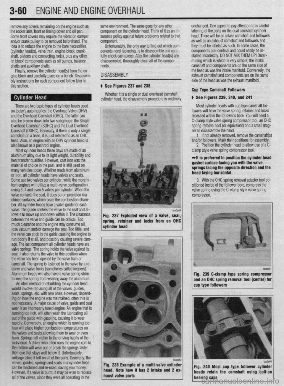
to keep the spring from wearing away the aluminum. Fig, 237 Exploded view of a valve, seal,
1 cylinder head ----r- 1 spring, retamer and locks from an OHC
An ideal method of rebuilding the cylinder head
would involve replacing all of the valves, guides,
seats, springs, etc. with new ones. However, depend-
ing on how the engine was maintained, often this is
not necessary. A major cause of valve, guide and seat
wear is an improperly tuned engine. An engine that is
~~f~t~~ rich, will often wash the lubricating oil
out ofthe guide with gasoline, causing it to wear
~~fdfy. lonely, an engine which is running too
lean wifl pface higher combustion temperatures on
Me valves and seats allowing them to wear or even
bum. Springs fall victim to the driving habits of the
f~~iduaf. A driver who often runs the engine rpm to
tfre redfine will wear out or break the springs faster
then one tfrat stays well below it. Unfortunately,
mileage takes it tot1 on all of the parts. Generally, the
valves, guides, springs and seats in a cylinder head
can be machined and re-used, saving you money.
.However, if a valve is burnt, it may be wise to replace
all of the valves, since they were all operating in the oi a multi-valve cylinder
t has 2 intake
and 2 ex-
At is preferred to position the cylinder head lasket’surtace facing you with tee valve
springs facing the opposite direction and the
lead laying horizontal.
3. With the OHC spring removal adapter tool po-
,itioned inside of the follower bore, compress the
alve spring using the C-clamp style valve spring
:ompressor.
tcca3p51 fig. 239 C-clamp type spring compressor
and an OHC spring removal tool (center) for
cup type followers
Fig. 240 Most cup type follower cylinder
/ heads retain the camshaft using bolt-on
bearing caps
Page 122 of 408
ENGINEAND ENGINEOVERHAUL 3-61
6. Withdraw the valve from the cylinder head. *Due to engine varnish, the retainer may
7. If equipped, remove the valve seal. stick to the valve locks. A gentle tap with a
*Special valve seal removal tools are avail- hammer may help to
break it loose.
able. Regular or needlenose type pliers, if 4. Remove the valve locks from the valve tip
used with care, will work
just as well. If us- and/or retainer. A small magnet may help in remov-
ing ordinary pliers, be sure not to damage ing the small locks.
the follower bore. The follower and its bore 5. Lift the valve spring, tool and all, off of the
are machined to close tolerances and any valve stem.
damage to the bore will effect this relation- 6. If equipped, remove the valve seal. If the seal
ship. is difl icult to remove wi ‘th the valve in place, try re-
8. If equip(jed, remove the valve spring shim. A moving the valve first, t hen the seal. Follow the steps
small magnetic tool or screwdriver will aid in re- below for valve removal I.
moval. 7. Position the head to allow access for with-
9. Repeat Steps 3 through 8 until all of the valves drawing the valve.
have been removed. - --.---a- LL-. L-..- -.-.. .~. . .
-Cylinder nears InaI nave seen a IOI or
**
nllrr rh..sr . . ..x.. *#....a . . . . . ..lmr~...r~
Rocker Arm Type Camshaft Followers
b See Figures 242 thru 250 mnes anuIul aUUJl IllcrY IIQVli lltUJllrUVlllliU
the valve lock gmve and/or tip, causing diffi-
. . _
-- -__- I -Z.L- ._-I__- I*.LI_ L-- L--
culty in
Dmuval UT me vane. II ms nas nap- nnnnd llse a metal file to carefully remove
pots around the lock grooves
n-s.. a:.- :. ---_--L ._ -II____ -- r-..--, ” Most cylinder heads with rocker arm-type the high s
camshaft followers are easily disassembled using a and/or tip. UIIIY IIIU II enuugn IU alluw NP standard valve spring compressor. However, certain moval.
models may not have enough open space around the
spring for the standard tool and may require you to 8. Remove the valve from the cylinder head.
use a C-clamp style compressor tool instead. 9. If equipped, remove the valve spring shim. A
1. If not already removed, remove the rocker small magnetic tool or screwdriver will aid in re-
arms and/or shafts and the camshaft. If applicable, moval.
- also remove the hydraulic lash adjusters. Mark their 10. Repeat Steps 3 though 9 until all of the valves
positions for assembly. have been removed.
2. Position the cylinder head to allow access to
the valve spring.
INSPECTION
3. Use a valve spring compressor tool to relieve
the spring tension from the retainer. Now that all of the cylinder head components are
clean, it’s time to inspect them for wear and/or dam- or screwunver WIII ala In removal.
5. Release the compressor tool and remove the
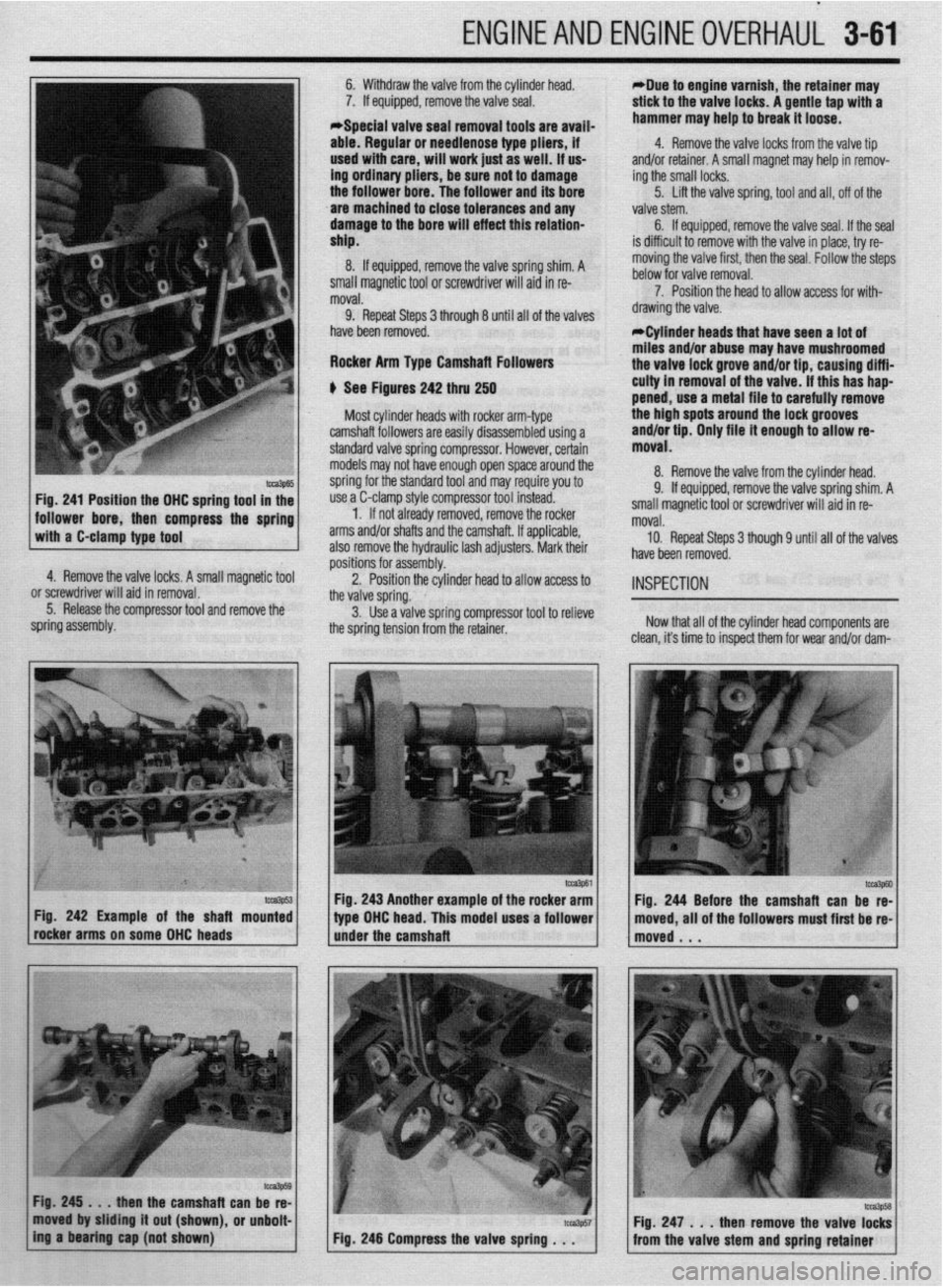
to?&55 Fig. 241 Position the DHC spring tool in the
follower bore, then compress the spring
with a C-clamp type tool
4. Remove the valve locks. A small magnetic tool
pring assembly.
Imp53 Fig. 242 Example of the shaft mounted
meker arms on some DHC heads
@Ja3Ps
Fig.245... then the camshaft can be re-
moved by sliding it out (shown), or unbolt-
ing a bearfng cap (not shown) Fig. 243 Another example of the rocker arm
type DHC head. This model uses a follower
iider the camshaft all of the followers must first be re
Page 123 of 408
.
3-62 ENGINEANDENGINEOVERHAUL
lge. To accurately inspect them, you will need some
,pecialized tools:
l A O-l in. micrometer for the valves l A dial indicator or inside diameter gauge for
he valve guides
l A spring ressure test gau e
If you do no P Yl have access to t e proper tools,
‘ou may want to bring the components to a shop
hat does.
lalves
1 See Figures 251 and 252
The first thing to inspect are the valve heads. Look
E :losely at the head, margin and face for any cracks,
rxcessive wear or burning. The margin is the best
)lace?o look for burning. It should have a squared E
c
edge with an even width all around the diameter.
When a valve burns, the margin will look melted and
the edges rounded. Also inspect the valve head for
any signs of tulipping. This will show as a lifting of
the edges or dishing in the center of the head and will
usually not occur to all of the valves. All of the heads
should look the same, any that seem dished more
than others are probably bad. Next, inspect the valve
lock grooves and valve tips. Check for any burrs
around the lock grooves, especially if you had to file
them to remove the valve. Valve tips should appear
flat, although slight rounding with high mileage en-
gines is normal. Slightly worn valve tips will need to
be machined flat. last, measure the valve stem diam-
eter with the micrometer. Measure the area that rides
within the guide, especially towards the tip where
most of the wear occurs. Take several measurements along its length and compare them to each other.
Wear should be even along the length with little to no
taper. If no minimum diameter is given in the specifi-
cations, then the stem should not read more than
0.001 in. (0.025mm) below the unworn area of the
valve stem. Any valves that fail these inspections
should be replaced.
Springs, Retainers and Valve Locks
$ See Figures 253 and 254
The first thing to check is the most obvious, bro-
ken springs. Next check the free length and square-
ness of each spring. If applicable, insure to distin-
guish between intake and exhaust springs. Use a
ruler and/or carpenter’s square to measure the length.
A carpenter’s square should be used to check the
lCZS3144
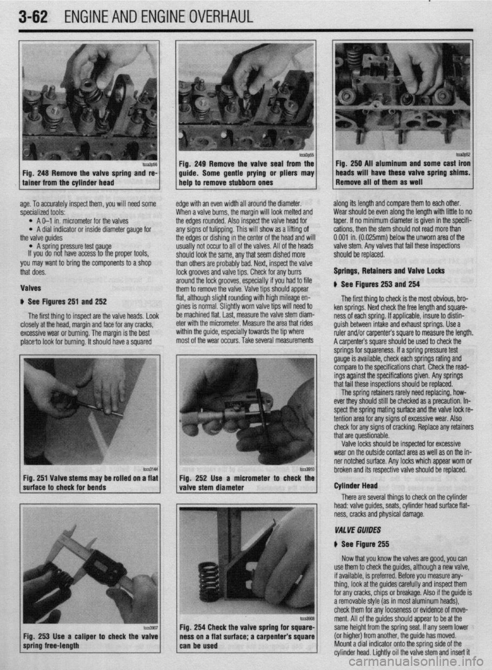
I I hrnknn itc Fig. 251 Valve stems may be rolled on a flat Fio. 252 Use a micrometer
suhace to check for bends
valve stem diameter r to check the
I
There are seve Cylinder Head
ral things to check on the cylinder
head: valve guides, seats, cylinder head surface flat-
ness, cracks and physical damage.
VA1 YE GUIDES
N See Figure 255
Now that you know the valves are good, you can
254 Check the valve spring fo
s on a flat surface; a carpenter use them to check the guides, although a new valve,
if available, is preferred. Before you measure any-
thing, look at the guides carefully and inspect them
for any cracks, chips or breakage. Also if the guide is
a removable style (as in most aluminum heads),
check them for any looseness or evidence of move-
ment. All of the guides should appear to be at the
same height from the spring seat. If any seem lower
(or higher) from another, the guide has moved.
Mount a dial indicator onto the sorina side of the
cylinder head. Lightly oil the valve stem and insert it
Page 124 of 408
ENGINEANDENGINEOVERHAUL 3-63
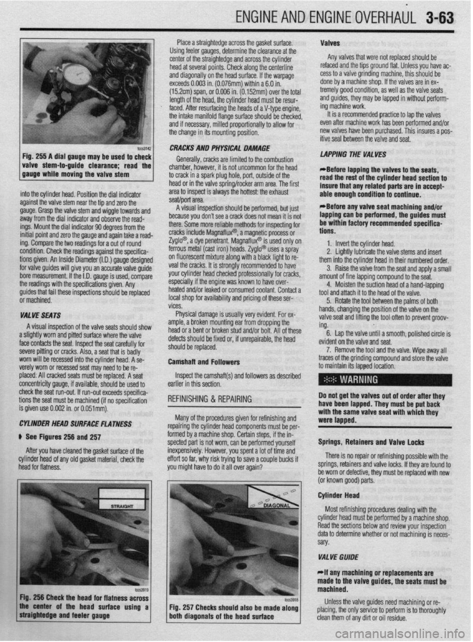
Place a straightedge across the gasket surface. Valves
Using feeler gauges, determine the clearance at the
center of the straightedge and across the cylinder Any valves that were not replaced should be
head at several points. Check along the centerline refaced and the tips ground flat. Unless you have ac-
and diagonally on the head surface. If the warpage cess to a valve grinding machine, this should be
exceeds 0.003 in. (0.076mm) within a 6.0 in. done by a machine shop. If the valves are in ex-
(152cm) span, or 0.006 in. (0.152mm) over the total tremely good condition, as well as the valve seats
length of the head, the cylinder head must be resur- and guides, they may be lapped in without petform-
,
I mg macnme worK.
4
It is a recnmmended practice to lap the valves faced. After resurfacing the heads of a V-type engine
the intake manifold flange surface should be checker,
and if necessary, milled proportionally to allow for
the change in its mounting position. _ - _ _ _ .- - - _
even after machine work has been p&formed and/or
new valves have been purchased. This insures a pos-
itive seal between the valve and seat.
-guide clearance; the 1
read
. .
into the cylinder head. Position the dial indicator
against the valve stem near the tie and zero the
gauge. Grasp the valve stem and’wiggle towards and
away from the dial indicator and observe the read-
ings. Mount the dial indicator 90 degrees from the
initial point and zero the gauge and again take a read-
ing. Compare the two readings for a out of round
condition. Check the readings against the specifica-
tions given. An Inside Diameter (I.D.) gauge designed
for valve guides will give you an accurate valve guide
bore measurement. If the I.D. gauge is used, compare
the readings with the specifications given. Any CRACKS AND PHYSICAL DAMAGE
Generally, cracks are limited to the combustion
chamber, hbwever, it is not uncommon for the head
to crack in a spark plug hole, port, outside of the
head or in the valve spring/rocker arm area. The first
area to inspect is always the hottest: the exhaust
.I *
seawpon area.
8 I .,“““I llly”Lv”l~ .ml”“l” - plr”llll”“, ““I ,“a’
because you don’t see a crack does not mean it is not
there. Some more reliable methods for inspecting for
cracks include Magnaflux? a magn$i,c process or
Zyglo? a dye penetrant. Ma{ -’
InatluxW IS used only on
ferrous metal (cast iron) heat Is. Zyglo@ uses a spray
on fluorescent mixture along with a black light to re-
veal the cracks. It is strongly recommended to have
your cylinder head checked professionally for cracks,
especially if the engine was known to have over-
I .* I,. ..^.. LAPPING THE VALVES
*Before iaoaino the valves to the seats,
read the rest of the cylinder head section to
insure that any related parts are in accept-
able enough condition to continue.
*Before anv valve seat machining and/or
lapping can be performed, the guides must
be within factory recommended specifica-
tions.
1. Invert the cylinder head.
2. Linhtlv Iuhrir;rB the valve stems and insert
-. _ ~ . . . . . .--.._-._
them into the cylinder head in their numbered order.
3. Raise the valve from the seat and apply a small
amount of fine lanninn compound to the seat.
4.
i guides that fail these inspections should be replaced nearea analor ieaKea or consumea coolant. Contact a Moisten the suction head of a hand-lapping
tool and attach it to the head of the valve.
i or machined. local shop for availability and pricing of these ser-
5. Rotate the tool between the palms of both
I vices.
I
VALVE SEATS Physical damage is usually very evident. For ex- hands, changing the position of the valve on the
valve seat and lifting the tool often to prevent groov-
A visual inspection of the valve seats should show
amnb P hrnbn mntlntinn ear from dropping the I and/or bolt. All of these ing.
.a,... . 6. Lap the valve until a smooth, polished circle is
a slightly worn and pitted surface where the valve
face contacts the seat. Inspect the seat carefully for
severe pitting or cracks. Also, a seat that is badly
worn will be recessed into the cylinder head. A se-
verely worn or recessed seat may need to be re- uetecIs SIIOUIO oe nxea or, IT unrepairaole, me neaa
should be replaced.
Camshaft and Followers evid
7
traces of the grinding corn
to maintain its lapped loca lent on the valve and seat.
‘. Remove the tool and the valve. Wipe away all
pound and store the valve
placed: All cracked seats must be replaced. A seat
concentricity gauge, if available, should be used to
check the seat run-out. If run-out exceeds specifica-
tions the seat must be machined (if no soecification
is given use 0.002 in. or O.O51mt$. Inspect the camshaft(s) and followers as described
earlier in this section.
REFINISHING & REPAIRING Do not get the valves out of order after they
have been lapped. They must be put back
: ..^^ I... --I:^:-L!-- --A
Many of the procedures gIveI
WI WIIIIISIIIIIIJ ~IIU repairing the cylinder head components must be per-
formed by a machine shop. Certain steps, if the in-
spected part is not worn, can be performed yourself
inexpensively. However, you spent a lot of time and
effort so far, why risk trying to save a couple bucks if
you might have to do it all over again?
I- with the same valve seat with which they
were lapped.
Springs, Retainers and Valve locks
There is no repair or refinishing possible with the
springs, retainers and valve locks. If they are found to
be worn or defective, they must be replaced with new
lor known nnod narts CYLtNDEt? HEAD SURFACE FLATNESS
) See Figures 256 and 257
After you have cleaned the gasket surface of the
cylinder head of any old gasket material, check the
head for flatness.
\- - a---r r- .-.
Cylinder Head
Most refinishing procedures dealing with the
VALVE GWDE
elf any machining or replacements are
e valve guides, the seats must be
Fig. 257 Checks should also be made along Unless the valve guides need machining or re-
placing, the only service to perform is to thoroughly‘
clean them of any dirt or oil residue.
Page 125 of 408
.
3-64 ENGINEANDENGINEOVERHAUL
There are only two types of valve guides used on
automobile engines: the replaceable-type (all alu-
minum heads) and the cast-in integral-type (most
cast iron heads). There are four recommended meth-
ods for repairing worn guides.
. Knurling
l Inserts l Reaming oversize l Replacing
Knurling is a process in which metal is displaced
and raised, thereby reducing clearance, giving a true
center, and providing oil control. It is the least ex-
pensive way of repairing the valve guides. However,
it is not necessarily the best, and in some cases, a
knurled valve guide will not stand up for more than
a short time. It requires a special knurlizer and pre-
cision reaming tools to obtain proper clearances. It
would not be cost effective to purchase these tools,
unless you plan on rebuilding several of the same
cylinder head.
Installing a guide insert involves machining the
guide to accept a bronze insert. One style is the coil-
type which is installed into a threaded guide. Another
is the thin-walled insert where the guide is reamed machined.
If the seats are in good condition, the valves can
be lapped to the seats, and the cylinder head assem-
bled. See the valves section for instructions on lap-
ping.
If the valve seats are worn, cracked or damaged,
they must be serviced by a machine shop. The valve
seat must be perfectly centered to the valve guide,
which requires very accurate machining.
CYLINDER HEAD SURFACE
If the cylinder head is warped, it must be ma-
chined flat. If the warpage is extremely severe, the
head may need to be replaced. In some instances, it
may be possible to straighten a warped head enough
to allow machining. In either case, contact a profes-
sional machine sh& for service. Cup Type Camshafl Followers
To install the springs, retainers and valve locks on
heads which have these components recessed into
the camshaft followers bore, you will need a small
I” .1.1.“1.“”
., ,, just after compressing the spring but before the *Any OHC cylinder head that shows exces-
sive warpage should have the camshaft bear-
ing journals align bored after the cylinder
head has been resurfaced. screwdriver-type tool, some clean white grease and a
lot of patience. You will also need the C-clamp style
spring compressor and the OHC tool used to disas-
semble the head.
1. Lightly lubricate the valve stems and insert all
of the valves into the cylinder head. If possible, main-
tain their original locations.
2. If equipped, install any valve spring shims
which were removed.
3. If equipped, install the new valve seals, keep-
ing the following in mind:
l If the valve seal presses over the guide,
lightly lubricate the outer guide surfaces.
l If the seal is an 0-rina tvoe. it rc rn+#fld
valve locks.
4. Place thevalve spring and retainer over the
stem.
5. Position the spring compressor and the OHC
tool, then compress the spring.
6. Using a small screwdriver as a spatula, fill
the valve stem side of the lock with white grease. Use
the excess grease on the screwdriver to fasten the
lock to the driver.
7. Carefully install the valve lock, which is stuck
to the end of the screwdriver, to the valve stem then
press on it with the screwdriver until the grease
squeezes out. The valve lock should now be stuck to
the stem.
8. Repeat Steps 6 and 7 for the remaining valve
lock. :
oversize to accept a split-sleeve insert. After the in-
sert is installed, a special tool is then run through the
guide to expand the insert, locking it to the guide.
The insert is then reamed to the standard size for
proper valve clearance.
Reamina for oversize valves restores normal clear- Failure to align bore the camshaft bearing
journals could result in severe engine dam-
age including but not limited to: valve and
oiston damage. connectinu rod damaoe,
iamshaft and/or crankshaft breakage,
antes and provides a true valve seat. Most cast-in
i tvpe guides can be reamed to accept an valve with an CRACKS AND PHYSICAL DAMAGE
oversize stem. The cost factor for this can become
quite high as you will need to purchase the reamer
and new, oversize stem valves for all guides which
were reamed. Oversizes are generally 0.003 to 0.030
in. (0.076 to 0.762mm), with 0.015 in. (0.381mm)
being the most common.
To replace cast-in type valve guides, they must be
drilled out, then reamed to accept replacement
guides, This must be done on a fixture which will al-
low centering and leveling off of the original valve
seat or quide, otherwise a serious guide-to-seat mis-
alignment may occur making it impossible to prop-
erly machine the seat.
Replaceable-type guides are pressed into the
cylinder head. A hammer and a stepped drift or
punch may be used to install and remove the guides.
Before removing the guides, measure the protrusion
on the spring side of the head and record it for instal-
tation. Use the stepped drift to hammer out the old
guide from the combustion chamber side of the head.
when in~llfng, determine whether or not the guide
also seals a water jacket in the head, and if it does,
use the ~o~ended sealing agent. If there is no
water jacket grease the valve guide and its bore. Use
the stepped drift, and hammer the new guide into the
cylinder head from the spring side of the cylinder
head. A stack af washers the same thickness as the
measured Eaton may help the installation Certain cracks can be repaired in both cast iron
and aluminum heads. For cast iron, a tapered
threaded insert is installed along the length of the
crack. Aluminum can also use the tapered inserts,
however welding is the preferred method. Some
physical damage can be repaired through brazing or
welding. Contact a machine shop to get expert advict
for your particular dilemma.
ASSEMBLY
+ See Figure 258
The first step for any assembly job is to have a
clean area in which to work. Next, thoroughly clean
all of the parts and components that are to be assem-
bled. Finally, place all of the components onto a suit-
able work space and, if necessary, arrange the parts
to their respective positions.
process.
VALVE SEATS
*Before any valve seat maChining can be
aerformed. the guides must be within factory
recommended specifications.
-
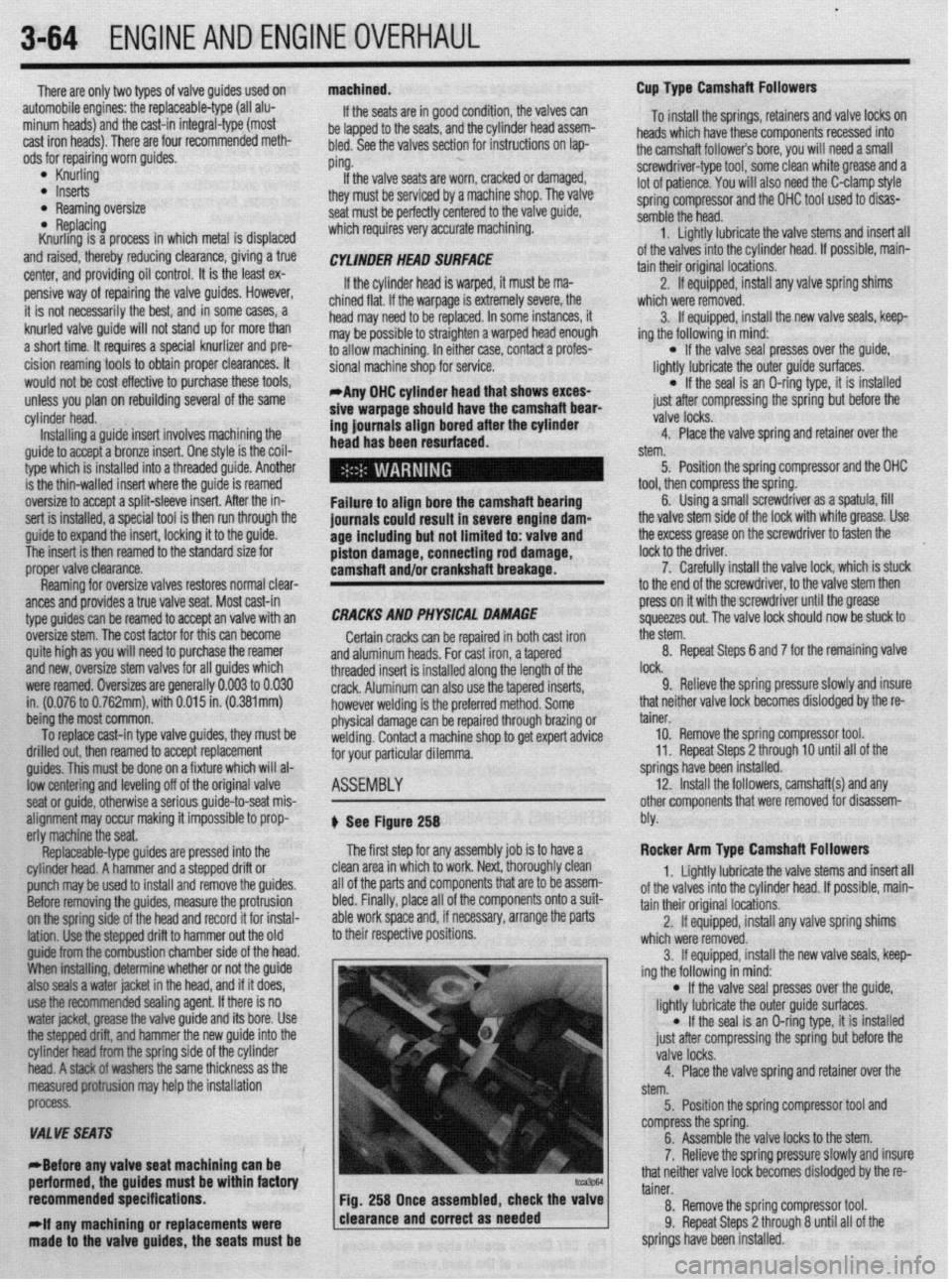
1 Fig. 258 Once assembled, check the valve
;
rlf any machtning or replacements were 1 clearance and correct as needed
I
made to the valve guides, the seats must be 9. Relieve the spring pressure slowly and insure
that neither valve lock becomes dislodged by the re-
tainer.
10. Remove the spring compressor tool.
11. Repeat Steps 2 through 10 until all of the
springs have been installed.
12. Install the followers, camshaft(s) and any
other components that were removed for disassem-
bly.
Rocker Arm Type Camshaft Followers
1. Lightly lubricate the valve stems and insert all
of the valves into the cylinder head. If possible, main-
tain their original locations.
2. If equipped, install any valve spring shims
which were removed.
3. If equipped, install the new valve seals, keep-
ing the following in mind:
l If the valve seal presses over the guide,
lightly lubricate the outer guide surfaces.
l If the seal is an O-ring type, it is installed
just after compressing the spring but before the
valve locks.
4. Place the valve spring and retainer over the
stem.
5. Position the spring compressor tool and
compress the spring.
6. Assemble the valve locks to the stem.
7. Relieve the spring pressure slowly and insure
that neither valve lock becomes dislodged by the re-
tainer.
8. Remove the spring compressor tool.
9. Repeat Steps 2 through 8 until all of the
springs have been installed.
Page 126 of 408
I)
ENGINEANDENGINEOVERHAUL 3-65
10. Install the camshaft(s), rockers, shafts and
any other components that were removed for disas-
sembly.
GENERAL INFORMATION ways number 1. However, depending on the engine
placement, the front of the engine could either be the
flywheel or damper/pulley end. Generally the front of
the engine faces the front of the vehicle. Use a num-
ber punch or scribe and also mark the main bearing
caps from front to rear with the front most cap being
number 1 (if there are five caps, mark them 1 through
5, front to rear).
A thorough overhaul or rebuild of an engine block
would include replacing the pistons, rings, bearings,
timing belt/chain assembly and oil pump. For OHV
engines also include a new camshaft and lifters. The
block would then have the cylinders bored and honed
oversize (or if using removable cylinder sleeves, new
sleeves installed) and the crankshaft would be cut
undersize to provide new wearing surfaces and per-
feet clearances. However, your particular engine may Take special care when pushing the connect-
ing rod up from the crankshaft because the
sharp threads of the rod bolts/studs will
score the crankshaft journal. Insure that spe-
cial plastic caps are installed over them, or
cut two pieces of rubber hose to do the
same.
Again, rotate the engine, this time to position the
number one cylinder bore (head surface) up. Turn the
crankshaft until the number one piston is at the bot-
tom of its travel, this should allow the maximum ac-
cess to its connecting rod. Remove the number one
connecting rods fasteners and cap and place two
lengths of rubber hose over the rod bolts/studs to
protect the crankshaft from damage. Using a sturdy
wooden dowel and a hammer, push the connecting
rod up about 1 in. (25mm) from the crankshaft and
remove the upper bearing insert. Continue pushing
or tapping the connecting rod up until the piston
rings are out of the cylinder bore. Remove the piston
and rod by hand, put the upper half of the bearing in-
sert back into the rod, install the cap with its bearing
insert installed, and hand-tighten the cap fasteners. If
the parts are kept in order in this manner, they will
not get lost and you will be able to tell which bear-
ings came form what cylinder if any problems are
discovered and diagnosis is necessary. Remove all
the other piston assemblies in the same manner. On
V-style engines, remove all of the pistons from one
bank, then reposition the engine with the other cylin-
der bank head surface up, and remove that banks nis-
prevent the assemblies from being removed,
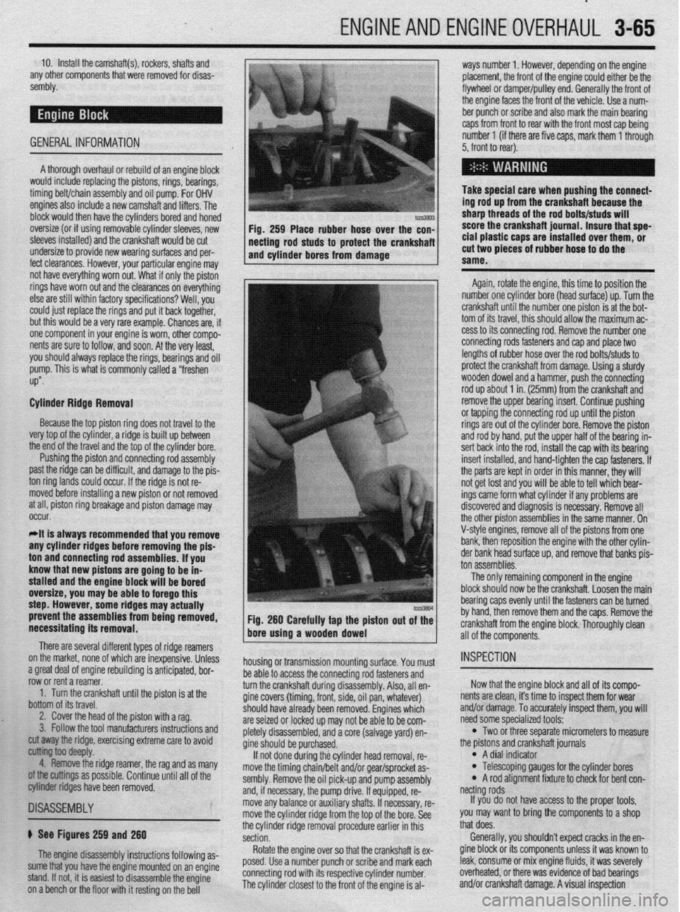
necessitating its removal. Fig. 260 Carefully tap the piston out of the
bore using a wooden dowel
There are several different types of ridge reamers
on the market, none of which are inexpensive, Unless
.3 “me.+ ,-ins, rdnnn;nn mh~lil.-linn ;I nn+:n:nnL.* l.^W
a ylwx “Gal “I cllylllc Ir;““ll”llly 13 dllLILlpxC”, ““I- row or rent a reamer.
1. Turn the crankshaft until the piston is at the
bottom of its travel.
2. Cover the head of the piston with a rag.
3. Follow the tool manufacturers instructions and housing or transmission mounting surface. You must
1 as many
II of the
~1SA~E~BLY
b See Figures 259 and 260
The engine disassembly instructions following as-
sume that you have the engine mounted on an engine
stand. If not, it is easiest to disassemble the engine
on a bench or the floor with it resting on the bell be able to access the connecting rod fasteners and
turn the crankshaft during disassembly. Also, all en-
gine covers (timing, front, side, oil pan, whatever)
should
are sei2
nletelv have already been removed. Engines which
,ed or locked up may not be able to be com-
r’-‘-‘, disassembled, and a core (salvage yard) en-
gine sh ould be purchased.
If no
t done during the cylinder head removal, re-
move the timing chain/belt and/or gear/sprocket as-
sembly. Remove the oil pick-up and pump assembly
and, if necessary, the pump drive. If equipped, re-
move any balance or auxiliary shafts. If necessary, re-
move the cylinder ridge from the top of the bore. See
the cylinder ridge removal procedure earlier in this
section.
Rotate the engine over so that the crankshaft is ex-
posed. Use a number punch or scribe and mark each
connecting rod with its respective cylinder number.
The cylinder closest to the front of the engine is al- cut away the ridge, exercising extreme care to avoid
~ ioo deepfy.
4. Remove the ridge reamer, the rag and
armings as possible. Continue until a
biter ridges have been removed. ton assemblies.
The only remaining component in the engine
block should now be the crankshaft. Loosen the main
bearing caps evenly until the fasteners can be turned
by hand, then remove them and the caps. Remove the
crankshaft from the engine block. Thoroughly clean
all of the components.
INSPECTION
Now that the engine block and all of its compo-
nents are clean, it’s time to inspect them for wear
and/or damage. To accurately inspect them, you will
need some specialized tools:
l Two or three separate micrometers to measure
the prstons and crankshaft journals
l A dial indicator l Telescoping gauges for the cylinder bores l A rod alignment fixture to check for bent con-
netting rods
If you do not have access to the proper tools,
you may want to bring the components to a shop
that does.
Generally, you shouldn’t expect cracks in the en-
gine block or its components unless it was known to
leak, consume or mix engine fluids, it was severely
overheated, or there was evidence of bad bearings
and/or crankshaft damage. A visual inspection
Page 127 of 408
3-66 ENGINEANDENGINEOVERHAUL
should be performed on all of the components, but
just because you don’t see a crack does not mean it
is not there. Some more reliable methods for inspect-
ing for cracks include Magnaflux? a magnetic
process or Zyglo@‘, a dye penetrant. Magnaflux@ is
used only on ferrous metal (cast iron). Zyglo@ uses a
spray on fluorescent mixture along with a black light
to reveal the cracks. It is strongly recommended to
have your engine block checked professionally for
cracks, especially if the engine was known to have
overheated and/or leaked or consumed coolant. Con-
tact a local shop for availability and pricing of these
services.
Engine Block
ENGINE BLOCK BEARING ALIGNMENT
Remove the main bearing caps and, if still in:
stalled, the main bearing inserts. Inspect all of the
main bearing saddles and caps for damage, burrs or
high spots. If damage is found, and it is caused from
a spun main bearing, the block will need to be align-
bored or, if severe enough, replacement. Any burrs or
high spots should be carefully removed with a metal
file.
Place a straightedge on the bearing saddles, in the
engine block, along the centerline of the crankshaft. If
any clearance exists between the straightedge and the
saddles, the block must be align-bored.
Align-boring consists of machining the main
bearing saddles and caps by means of a flycutter that
runs through the bearing saddles.
DECK FLATNESS
The top of the engine block where the cylinder
head mounts is called the deck. Insure that the deck
surface is clean of dirt, carbon deposits and old gas-
ket material. Place a straightedge across the surface
of the deck along its centerline and, using feeler
gauges, check the clearance along several points. Re-
peat the checking procedure with the straightedge
placed along both diagonals of the deck surface. If
the reading exceeds 0.003 in. (0.076mm) within a 6.0
in. (152cm) span, or 0.006 in. (0.152mm) over the
total length of the deck, it must be machined.
CYLINDER BORES
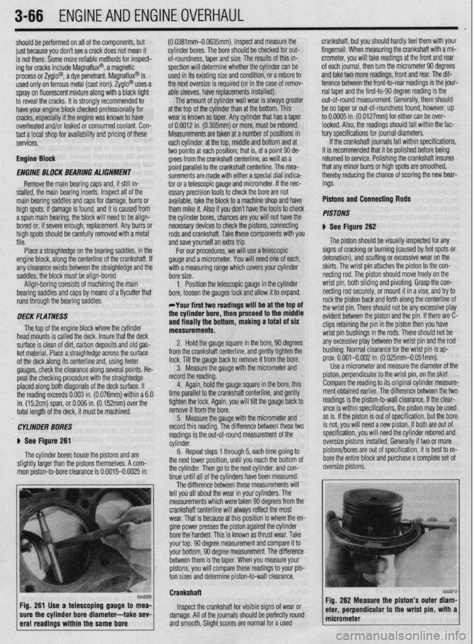
$ See Figure 261
The cylinder bores house the pistons and are
slightly larger than the pistons themselves. A com-
mon piston-to-bore clearance is 0.0015-0.0025 in. (0.0381mm-O.0635mm). Inspect and measure the
cylinder bores. The bore should be checked for out-
of-roundness, taper and size. The results of this in-
spection will determine whether thecylinder can be
used in its existing size and condition, or a rebore to
the next oversize is required (or in the case of remov-
able sleeves, have replacements installed).
The amount of cylinder wall wear is always greater
at the top of the cylinder than at the bottom. This
wear is known as taper. Any cylinder that has a taper
of 0.0012 in. (0.305mm) or more, must be rebored.
Measurements are taken at a number of positions in
each cylinder: at the top, middle and bottom and at
two points at each position; that is, at a point 90 de-
grees from the crankshaft centerline, as well as a
point parallel to the crankshaft centerline. The mea-
surements are made with either a special dial indica-
tor or a telescopic gauge and micrometer. If the nec-
essary precision tools to check the bore are not
available, take the block to a machine shop and have
them mike it. Also if you don’t have the tools to check
the cylinder bores, chances are you will not have the
necessary devices to check the pistons, connecting
rods and crankshaft. Take these components with you
and save yourself an extra trip.
For our procedures, we will use a telescopic
gauge and a micrometer. You will need one of each,’
with a measuring range which covers your cylinder
bore size.
1, Position the telescopic gauge in the cylinder
bore, loosen the gauges lock and allow it to expand.
*Your first two readings will be at the top of
the cylinder bore, then proceed to the middle
and finally the bottom, making a total of six
measurements.
2. Hold the gauge square in the bore, 90 degrees
from the crankshaft centerline, and gently tighten the
lock. Tilt the gauge back to remove it from the bore.
3. Measure the gauge with the micrometer and
record the reading.
4. Again, hold the gauge square in the bore, this
time parallel to the crankshaft centerline, and gently
tighten the lock. Again, you will tilt the gauge back to
remove it from the bore.
5. Measure the gauge with the micrometer and
record this reading. The difference between these two
readings is the out-of-round measurement of the
cylinder.
6. Repeat steps 1 through 5, each time going to
the next lower position, until you reach the bottom of
the cylinder. Then go to the next cylinder, and con-
tinue until all of the cylinders have been measured.
The difference between these measurements will
tell you all about the wear in your cylinders. The
measurements which were taken 90 degrees from the
crankshaft centerline will always reflect the most
wear.,That is because at this position is where the en-
gine power presses the piston against the cylinder
bore the hardest. This is known as thrust wear. Take
your top, 90 degree measurement and compare it to
your bottom, 90 degree measurement. The difference
between them is the taper. When you measure your
pistons, you will compare these readings to your pis-
ton sizes and determine piston-to-wall clearance. crankshaft, but you should hardly feel them with your
fingernail. When measuring the crankshaft with a mi-
crometer, you will take readings at the front and rear
of each journal, then turn the micrometer 90 degrees
and take two more readings, front and rear. The dif-
ference between the front-to-rear readings is the jour-
nal taper and the first-to-90 degree reading is the
out-of-round measurement. Generally, there should
be no taper or out-of-roundness found, however, up
to 0.0005 in. (0.0127mm) for either can be over-
looked. Also, the readings should fall within the fac-
tory specifications for journal diameters.
If the crankshaft journals fall within specifications,
it is recommended that it be polished before being
returned to service. Polishing the crankshaft insures
that any minor burrs or high spots are smoothed,
thereby reducing the chance of scoring the new bear-
ings.
Pistons and Connecting Rods
PISTONS
N See Figure 262
The piston should be visually inspected for any
signs of cracking or burning (caused by hot spots or
detonation), and scuffing or excessive wear on the
skirts. The wrist pin attaches the piston to the con-
netting rod. The piston should move freely on the
wrist pin, both sliding and pivoting. Grasp the con-
netting rod securely, or mount it in a vise, and try to
rock the piston back and forth along the centerline of
the wrist pin. There should not be any excessive play
evident between the piston and the pin. If there are C-
clips retaining the pin in the piston then you have
wrist pin bushings in the rods. There should not be
any excessive play between the wrist pin and the rod
bushing. Normal clearance for the wrist pin is ap-
prox. 0.001-0.002 in. (0.025mm-0.051mm).
Use a micrometer and measure the diameter of the
piston, perpendicular to the wrist pin, on the skirt.
Compare the reading to its original cylinder measure-
ment obtained earlier. The difference between the two
readings is the piston-to-wall clearance. If the clear-
ante is within specifications, the piston may be used
as is. If the piston is out of specification, but the bore
is not, you will need a new piston. If both are out of
specification, you will need the cylinder rebored and
oversize pistons installed. Generally if two or more
pistons/bores are out of specification, it is best to re-
bore the entire block and purchase a complete set of
oversize pistons.
Crankshaft
Inspect the crankshaft for visible signs of wear or
damage. All of the journals should be perfectly round
and smooth. Slight scores are normal for a used
Page 128 of 408
ENGINEANDENGINEOVERHAUL 3-67
CONNECTING ROD
You should have the connecting rod checked for
StraiQhtness at a machine shop. If the connecting rod
is bent, it will unevenly wear the bearing and piston,
as well as place greater stress on these components.
Any bent or twisted connecting rods must be re-
placed. If the rods are straight and the wrist pin clear-
ance is within specifications, then only the bearing
end of the rod need be checked. Place the connecting
rod into a vice, with the bearing inserts in place, in-
stall the cap to the rod and torque the fasteners to
specifications. Use a telescoping gauge and carefully
measure the inside diameter of the bearings. Com-
pare this reading to the rods original crankshaft jour-
nal diameter measurement. The difference is the oil
clearance. If the oil clearance is not within specifica-
tions, install new bearings in the rod and take another
.
specifica- L
need to
shop as the pistons must be installed in the con measurement. it the Clearance is still out of :
tions, and the crankshaft is not, the rod will
be reconditioned by a machine shop.
*You can also use Plastigage’
@to check the
bearing clearances. The assen- . ...= - _______
Mm sectinn has complete instructions on its use.
Camshaft
Inspect the camshaft and lifters/followers as de
scribed earlier in this section.
Bearings
All of the enaine bearinos should be visuallv in-
~~~ I~ .- - -- ..-_-..,
spected for we; and/or damage. The bearing should
look evenly worn all around with no deep scores or
pits. If the bearing is severely worn, scored, pitted or
heat blued, then the bearing, and the components
that use it, should be brought to a machine shop for
block. ,ect
relationshipto the rod or engine damage can occur,
Pistons and Connecting Rods
I
b See Fiaute 264 --- --*------
Only pistons with the wrist pin retained by C-clips
are serviceable by the home-mechanic. Press fit pis-
tons require special presses and/or heaters to re- I”
rr
rove/install the connecting rod and should only be
PC srformed by a machine shop.
All pistons will have a mark indicating the direc-
tir 9n to the front of the engine and the must be in-
stalled into the engine in that manner. Usually it is a
notch or arrow on the top of the piston, or it may be
the letter F cast or stamped into the piston.
ASEtiBlY
1
crankshaft. Replace any freeze or oil galley plugs
which were removed during disassembly.
Crankshaft
u See Figures 265, 266, 267, and 266
1. Remove the main bearing inserts from the
block and bearing caps.
2. If the crankshaft main bearing journals have
been refinished to a definite undersize, install the
correct undersize bearina. Be sure that the bearina
inserts and bearing bores are clean. Foreign mateiial
under inserts will distort bearinq and cause failure.
3. Place the upper main bearing inserts in bores
*The oil holes in the bearing inserts must
be aligned with the oil holes in the cylinder
. . .
inspection. Full-circle bearings (used on most
camshafts, auxiliary shafts, balance shafts, etc.) re-
quire specialized tools for removal and installation, ’
and should be brought to a machine shop for service.
Oil Pump Before you begin assembling the engine, first give
yourself a clean, dirt free work area. Next, clean every
engine component again. The key to a QOOd assem-
hhr io da~nlinmw “‘I Ia ~rGiOllll,lc7.Ja. Mount the engine block into the engine stand and
II
*The oil pump is responsible fo
r providing wasn It one last time usmg water and detergent (dish-
unrhinn rldarnant ~nrirc well), While washing it, with a soft bristle brush and
: oil oassaoes. Comoletelv constant lubrication to the whole engine and 1ILl.M 0, ,y “GSGl ycx II ““1 n
so it is recommended that a new oil pump be scrub the cylinder bore:
installed when rebuilding the engine. thoroughly clean all oft
dry the engine and spra
Completely disassemble the oil pump and thor- with an anti-rust solutio
oughly clean all of the components. Inspect the oil
pro
pump Qears and housing for wear and/or damage. In- exe
sure that the pressure relief valve operates properly sac
and there is no binding or sticking due to varnish or
debris. If all of the parts are in proper working condi-
tion, lubricate the gears and relief valve, and assem-
r
j ht
y the entire assembly down’
in such as WD-4Q@ or similar Fig. 265 Apply a strip of gauging material
Iduct. Take a clean lint-free rag and wipe up any
less anti-rust solution from the bores, bearing
Idles, etc. Repeat the final cleaning process on the !torguethe~~p * ,’ / to the bearmg lournal, then mstall and
ble the pump.
REFINISHING
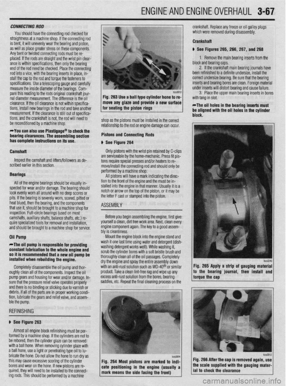
# See Figure 263
Almost all engine block refinishing must be per-
I
IUIIII~U uy a macnme snap. ir me cynnoers are nor ro
be rebored, then the cylinder glaze can be removed
with a ball hone. When removing cylinder glaze with
a ball hone, use a light or penetrating type oil to Iu-
bricate the hone. Do not allow the hone to run dry as
this may cause excessive scoring of the cylinder
bores and wear on the hone. If new pistons are re-
quired, they will need to be installed to the connect-
ing rods. This should be oerformed bv a machine Fig. 266 After the cap is removed again, use
Page 129 of 408
.
3-68 ENGINEANDENGINEOVERHAUL
crankshaft end-play 8. Install the rear main seal.
the inner portion of the lower land. If the lower
9. After the bearings have been fitted, apply a
lands have high steps, the piston should be re-
light coat of engine oil to the journals and bearings.
placed.
Install the rear main bearing cap. Install all bearing
2. Unless new pistons are installed, be sure to
caps except the thiust bearing cap. Be sure that main
I
install the pistons in the cylinders from which they
bearing caps are installed in original locations.
were removed. The numbers on the connecting rod
Tighten the bearing cap bolts to specifications.
and bearing cap must be on the same side when in-
10. Install the thrust bearing cap with bolts fin-
stalled in the cylinder bore. If a connecting rod is
ger-tight.
ever transposed from one engine or cylinder to an-
11. Pry the crankshaft forward against the thrust
other, new bearings should be fitted and the connect-
surface of upper half of bearing.
ing rod should be numbered to correspond with the *
12. Hold the crankshaft forward and pry the thrust
new cylinder number. The notch on the piston head
bearing cap to the rear. This aligns the thrust sur-
goes toward the front of the engine.
faces of both halves of the bearing.
3. Install all of the rod bearing inserts into the
13. Retain the forward pressure on the crankshaft.
rods and caps.
Tighten the cap bolts to specifications.
4. Install the rings to the pistons. Install the oil
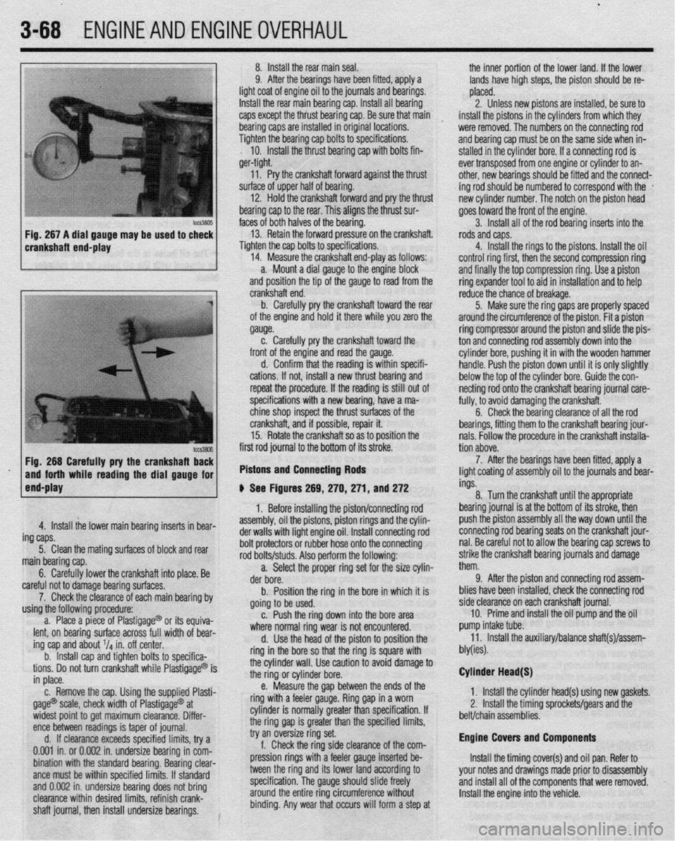
14. Measure the crankshaft end-play as follows:
control ring first, then the second compression ring
a. Mount a dial gauge to the engine block
and finally the top compression ring. Use a piston
and position the tip of the gauge to read from the
ring expander tool to aid in installation and to help
Fig. 266 Carefully pry the crankshafl Ez
and forth while reading the dial gauge for
end-play first rod journal to the bottom of its stroke.
Pistons and Connecting Rods
4. Install the lower main bearing inserts in bear-
ing caps.
5. Clean the mating surfaces of block and rear
main bearing cap.
6. Carefully lower the crankshaft into place. Be
careful not to damage bearing surfaces.
7. Check the clearance of each main bearing by
using the following procedure:
a. Place a piece of Plastigage@ or its equiva-
lent, on bearing surface across full width of bear-
ing cap and about V4 in. off center.
b. Install cap and tighten bolts to specifica-
tions. Do not turn crankshaft while Plastigage@ is
in place.
c. Remove the cap. Using the supplied Plasti-
gage@ scale, check width of Plastigage@ at
widest point to get maximum clearance. Differ-
ence between readings is taper of journal.
d. If clearance exceeds specified limits, try a
0.001 in. or 0.002 in. undersize bearing in com-
bination with the standard bearing. Bearing clear-
ante must be within specified limits. If standard
and 0.002 in. undersize bearing does not bring
clearance within desired limits, refinish crank-
shaft journal, then install undersize bearings. crankshaft end.
b. Carefully pry the crankshaft toward the rear
of the engine and hold it there while you zero the
gauge.
c. Carefully pry the crankshaft toward the
front of the engine and read the gauge.
d. Confirm that the reading is within specifi-
cations. If not, install a new thrust bearing and
repeat the procedure. If the reading is still out of
specifications with a new bearing, have a ma-
chine shop inspect the thrust surfaces of the
crankshaft, and if possible, repair it.
15. Rotate the crankshaft so as to position the
# See Figures 269, 270,271, and 272
1. Before installing the piston/connecting rod
assembly, oil the pistons, piston rings and the cylin-
der walls with light engine oil. Install connecting rod
bolt protectors or rubber hose onto the connecting
rod bolts/studs. Also perform the following:
a. Select the proper ring set for the size cylin-
der bore.
b. Position the ring in the bore in which it is
going to be used.
c. Push the ring down into the bore area
where normal ring wear is not encountered.
d. Use the head of the piston to position the
ring in the bore so that the ring is square with
the cylinder wall. Use caution to avoid damage to
the ring or cylinder bore.
e. Measure the gap between the ends of the
ring with a feeler gauge. Ring gap in a worn
cylinder is normally greater than specification. If
the ring gap is greater than the specified limits,
try an oversize ring set.
f. Check the ring side clearance of the com-
pression rings with a feeler gauge inserted be-
tween the ring and its lower land according to
specification. The gauge should slide freely
around the entire ring circumference without
binding. Any wear that occurs will form a step at reduce the chance of breakage.
5. Make sure the ring gaps are properly spaced
around the circumference of the piston. Fit a piston
ring compressor around the piston and slide the pis-
ton and connecting rod assembly down into the
cylinder bore, pushing it in with the wooden hammer
handle. Push the piston down until it is only slightly
below the top of the cylinder bore. Guide the con-
netting rod onto the crankshaft bearing journal care-
fully, to avoid damaging the crankshaft.
6. Check the bearing clearance of all the rod
bearings, fitting them to the crankshaft bearing jour-
nals. Follow the procedure in the crankshaft installa-
tion above.
7. After the bearings have been fitted, apply a
light coating of assembly oil to the journals and bear-
ings.
8. Turn the crankshaft until the appropriate
bearing journal is at the bottom of its stroke, then
push the piston assembly all the way down until the
connecting rod bearing seats on the crankshaft jour-
nal. Be careful not to allow the bearing cap screws to
strike the crankshaft bearing journals and damage
them.
9. After the piston and connecting rod assem-
blies have been installed, check the connecting rod
side clearance on each crankshaft journal.
10. Prime and install the oil pump and the oil
pump intake tube.
11. Install the auxiliary/balance shaft(s)/assem-
bly(ies).
Cylinder Head(S)
1. Install the cylinder head(s) using new gaskets.
2, Install the timing sprockets/gears and the
belt/chain assemblies.
Engine Covers and Components
Install the timing cover(s) and oil pan. Refer to
your notes and drawings made prior to disassembly
and install all of the components that were removed.
Install the engine into the vehicle.
Page 130 of 408
ENGINEANDENGINEOVERHAUL 3-69
STARTING THE ENGINE
clearance using the ring and a Now that the engine is installed and every wire and
hose is properly connected, go back and double
check that all coolant and vacuum hoses are con-
, netted. Check that your oil drain plug is installed and
tt tl
C ti
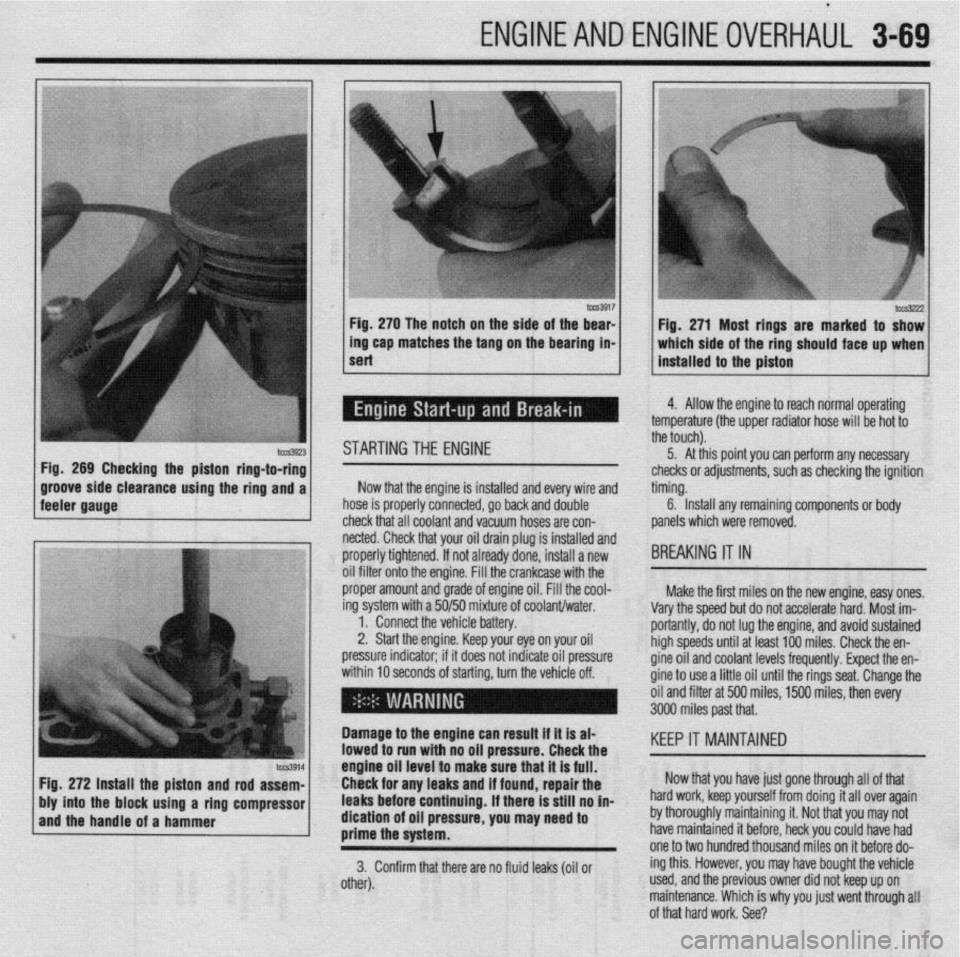
hYs3222 Fig. 271 Most rings are marked to show
which side of the ring should face up when
installed to the piston
J
4. Allow the engine to reach normal operating
?mperature (the upper radiator hose will be hot to
ie touch).
5. At this point you can perform any necessary
hecks or adjustments, such as checking the ignition
ming.
6. Install any remaining components or body
anels which were removed.
IREAKING IT IN
Make the first miles on the new engine, easy ones.
arv the soeed but do not accelerate hard. Most im-
oriantly, do not lug the engine, and avoid sustained
igh speeds until at least 100 miles. Check the en-
ine oil and coolant levels frequently. Expect the en-
ine to use a little oil until the rings seat. Change the
il and filter at 500 miles, 1500 miles, then every