MITSUBISHI DIAMANTE 1900 Repair Manual
Manufacturer: MITSUBISHI, Model Year: 1900, Model line: DIAMANTE, Model: MITSUBISHI DIAMANTE 1900Pages: 408, PDF Size: 71.03 MB
Page 171 of 408
4-28 DRIVEABILITYAND EMISSIONS CONTROLS
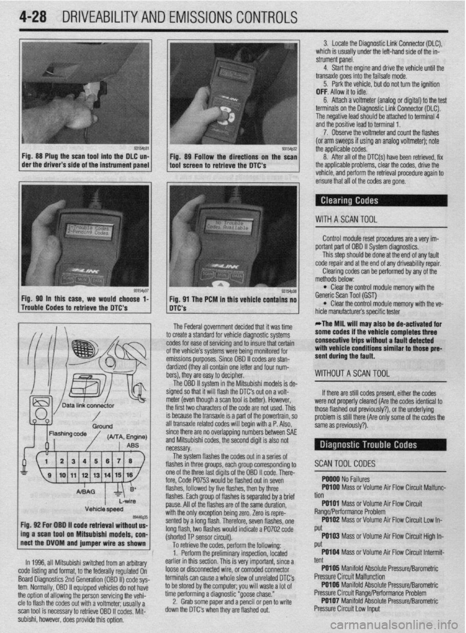
Fig. 88 Plug the scan tool into the DLC un-
Fig. 89 Follow the directions on the scan
der the driver’s side of the instrument panel
tool screen to retrieve the DTC’s 3. Locate the Diagnostic Link Connector (DLC),
which is usually under the left-hand side of the in-
strument panel.
4. Start the engine and drive the vehicle until the
transaxle goes into the failsafe mode.
5. Park the vehicle, but do not turn the ignition
OFF. Allow it to idle.
6. Attach a voltmeter (analog or digital) to the test
terminals on the Diagnostic Link Connector (DLC).
The negative lead should be attached to terminal 4
and the positive lead to terminal 1.
7. Observe the voltmeter and count the flashes
(or arm sweeps if using an analog voltmeter); note
the applicable codes.
- 8. After all of the DTC(s) have been retrieved, fix
the applicable problems, clear the codes, drive the
vehicle, and perform the retrieval procedure again to
ensure that all of the codes are gone.
WITHASCANTOOL
Control module reset procedures are a very im-
portant part of OBD II System diaqnostics.
This step should be done at the end of any fault
code repair and at the end of any driveability repair.
Clearing codes can be performed by any of the
Fig. 90 in this case, we would choor- A ’ ma*-. . . * .
Trouble Codes to retrieve the DTC’s
-.- -
A mere mar
. . methods below: l Clear the control module memory with the
se l-
I I ng. vi me rtim In mts venicie contains no Generic Scan Tool (GST) l DTC’S Clear the control module memory with the ve-
L’-‘m iufacturer’s specific tester
The Federal government decided that it was time
to create a standard for vehicle diagnostic systems
codes for ease of servicing and to insure that certain
of the vehicle’s systems were being monitored for
emissions purposes. Since OBD II codes are stan-
dardized (they all contain one letter and four num-
bers), they are easy to decipher.
The OBD II system in the Mitsubishi models is de-
signed so that it will flash the DTC’s out on a volt-
meter (even though a scan tool is better). However,
the first two characters of the code are not used. This
is because the transaxle is a part of the powertrain, so
all transaxle related codes will begin with a P. Also, *The MIL will may also be de-activated for
some codes if the vehicle completes three
consecutive trips without a fault detected
with vehicle conditions similar to those pre-
sent during the fault.
WITHOUTASCAN TOOL
If there are still codes p
resent, either the codes
were not properly cleared f
:Are the codes identical to
those flashed out previous
I$‘), or the underlying
problem is still there (Are I
only some of the codes the
same as oreviouslv?).
since there are no overlapping numbers between SAE
and Mitsubishi codes, the second digit is also not
necessary.
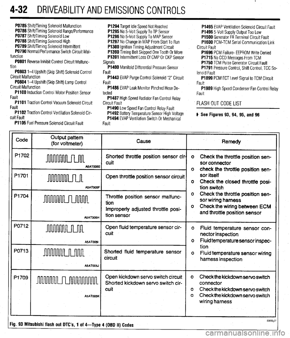
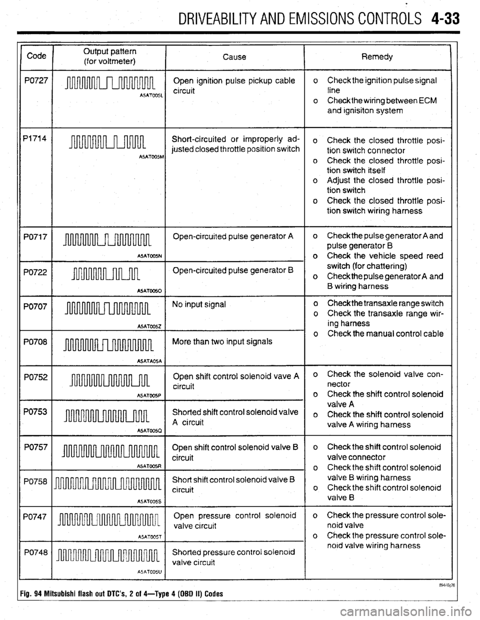
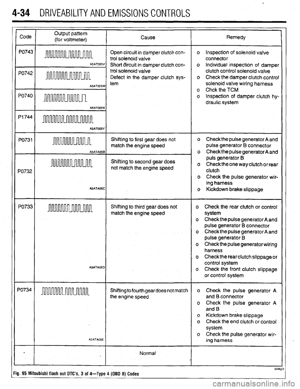
The system flashes the codes o
ut ma series of
flashes in
three nmm mh nrnlll -- J.-lr-, ---.. ~.--
p corresponding to
one of the
three last diaits of the OBD II code. There-
fore, Code WJJ wuuw UC:
IIKWAJ WI III XVWI flashes, followed by five flashes, then by three
flashes. Each group of flashes is se
pause. All of the flashes are of the (
witi the or$, nvrontinn hoinn mm sented by z
long flash,
(shorted Tt SWIWI LIIW. rparated by a brief
;ame duration,
88, “rw”I.‘L’“‘I uv,,,y LUI”.
Zero is repre-
1 long flash. Therefore, seven flashes, one
two flashes would indicate a PO702 code
3 nnmn^r ,.:*....:I I r
SCANTOOLCODES
. YYY” I ‘I” I cuI”I”.J PO100 Mass or Volume Air Flow Circuit Malfunc-
Lb
non
PO101 Mass orVolume Air Flow Circuit
Range/Performance Problem
PO102 Mass or Volume Air Flow Circuit Low In-
Put
.
To retrieve the codes, perform the following: PO103 Mass or Volume Air Flow Circuit High In-
i Put
1. Perform the preliminary inspection, located PO104 Mass or Volume Air Flow Circuit Intermit-
-;
Vehicle speed es446e35 Fig. 92 For OBO ii code retrieval without us-
ing a scan tool on Mitsubishi models, con-
nect the DVOM and jumper wire as shown
In 1996, all Mitsubishi switched from an arbitrary
code listing and format, to the federally regulated On
Board Diagnostics 2nd Generation (OBD II) code sys-
tern. Normally, OBD II equipped vehicles do not have
the option of allowing the person servicing the vehi-
cle to flash the codes out with a voltmeter; usually a
scan tool is necessary to retrieve OBD II codes. Mit-
subishi, however, does provide this option, earlier in this section. This is very important, since a
loose or disconnected wire, or corroded connector
terminals can cause a whole slew of unrelated DTC’s
to be stored by the computer; you will waste a lot of
time performing a diagnostic “goose chase.”
2. Grab some paper and a pencil or pen to write
down the DTC’s when they are flashed out. tent
PO105 Manifold Absolute Pressure/Barometric
Pressure Circuit Malfunction
PO106 Manifold Absolute Pressure/Barometric
Pressure Circuit Range/Performance Problem
PO107 Manifold Absolute Pressure/Barometric
Pressure Circuit Low Input
Page 172 of 408
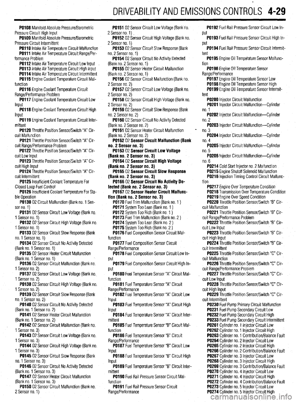
DRIVEABILITYAND EMISSIONS CONTROLS 4-29
PO108 Manifold Absolute Pressure/Barometric
Pressure Circuit High Input
PO109 Manifold Absolute Pressure/Barometric
Pressure Circuit Intermittent
PO110 intake Air Temperature Circuit Malfunction
PO111 Intake Air Temperature Circuit Range/Per-
formance Problem
PO112 Intake Air Temperature Circuit Low Input
PO113 Intake Air Temoerature Circuit Hiah lnout
PO114 Intake Air Temberature Circuit lnt&miitent
PO115 Engine Coolant Temperature Circuit Mal-
function -
PO116 Engine Coolant Temperature Circuit
Range/Performance Problem
PO117 Engine Coolant Temperature Circuit Low
Input
PO118 Engine Coolant Temperature Circuit High
Input
PO119 Engine Coolant Temperature Circuit Inter-
mittent
PO120 Throttle Position Sensor/Switch “A” Cir-
cuit Malfunction
PO121 Throttle Position Sensor/Switch “A” Cir-
cuit Range/Performance Problem
PO122 Throttle Position Sensor/Switch “A” Cir-
cuit Low Input
PO123 Throttle Position Sensor/Switch “A” Cir-
cuit High Input
PO124 Throttle Position Sensor/Switch “A” Cir-
cuit Intermittent
PO125 Insufficient Coolant Temperature For
Closed Loop Fuel Control
PO126 Insufficient Coolant Temperature For Sta-
ble Operation
PO130 02 Circuit Malfunction (Bank no. 1 Sen-
sor no. 1)
PO131 02 Sensor Circuit Low Voltage (Bank no.
1 Sensor no. 1)
PO132 02 Sensor Circuit High Voltage (Bank no.
1 Sensor no. 1)
PO133 02 Sensor Circuit Slow Response (Bank
no. 1 Sensor no. 1)
PO134 02 Sensor Circuit No Activity Detected
(Bank no. 1 Sensor no. 1)
PO135 02 Sensor Heater Circuit Malfunction
(Bank no. 1 Sensor no. 1)
PO136 02 Sensor Circuit Malfunction (Bank no.
1 Sensor no. 2)
PO137 02 Sensor Circuit Low Voltage (Bank no.
1 Sensor no. 2)
PO138 02 Sensor Circuit High Voltage (Bank no.
1 Sensor no. 2)
PO139 02 Sensor Circuit Slow Response (Bank
no. 1 Sensor no. 2)
PO140 02 Sensor Circuit No Activity Detected
(Bank no. 1 Sensor no. 2)
PO141 02 Sensor Heater Circuit Malfunction
(Bank no. 1 Sensor no. 2)
PO142 02 Sensor Circuit Malfunction (Bank no.
1 Sensor no. 3)
PO143 02 Sensor Circuit Low Voltage (Bank no.
1 Sensor no. 3)
PO144 02 Sensor Circuit High Voltage (Bank no.
1 Sensor no. 3)
PO145 02 Sensor Circuit Slow Response (Bank
no. 1 Sensor no. 3)
PO146 02 Sensor Circuit No Activity Detected
(Bank no. 1 Sensor no. 3)
PO147 02 Sensor Heater Circuit Malfunction
(Bank no. 1 Sensor no. 3)
PO150 02 Sensor Circuit Malfunction (Bank no.
2 Sensor no. 1) PO151 02 Sensor Circuit Low Voltage (Bank no.
2 Sensor no. 1)
PO152 02 Sensor Circuit High Voltage (Bank no.
2 Sensor no. 1)
PO153 02 Sensor Circuit Slow Response (Bank
no. 2 Sensor no. 1)
PO154 02 Sensor Circuit No Activity Detected
(Bank no. 2 Sensor no. 1)
PO155 02 Sensor Heater Circuit Malfunction
(Bank no. 2 Sensor no. 1)
PO156 02 Sensor Circuit Malfunction (Bank no.
2 Sensor no. 2)
PO157 02 Sensor Circuit Low Voltage (Bank no.
2 Sensor no. 2)
PO158 02 Sensor Circuit High Voltage (Bank no.
2 Sensor no. 2)
PO159 02 Sensor Circuit Slow Response (Bank
no. 2 Sensor no. 2)
PO160 02 Sensor Circuit No Activity Detected
(Bank no. 2 Sensor no. 2)
PO161 02 Sensor Heater Circuit Malfunction
(Bank no. 2 Sensor no. 2)
PO162 02 Sensor CircuitMalfunction(8ank
no.2 Sensorno.3)
PO16302 Sensor Circuit Low Voltage
(Bankno. Sensorno.3)
PO16402 Sensor Circuit HighVoltage
(Bankno. Sensorno.3)
PO16502 Sensor Circuit Slow Response
(Bankno. Sensorno.3)
PO166 02 Sensor Circuit No Activity De-
tected(Bankno.2 Sensorno.3)
PO16702 SensorHeaterCircuitMalfunc-
tion(Bank no.2 Sensorno.3)
PO170 Fuel Trim Malfunction (Bank no. 1 )
PO171 System Too Lean (Bank no. 1 )
PO172 Svstem Too Rich (Bank no 1 )
PO173 F;el Trim Malfundtion (Bank io. 2 )
PO174 System Too Lean (Bank no 2 )
PO175 System Too Rich (Bank no. 2 )
PO176 Fuel Composition Sensor Circuit Mal-
function
PO177 Fuel Composition Sensor Circuit
Range/Performance
PO178 Fuel Composition Sensor Circuit Low In-
put
PO179 Fuel Composition Sensor Circuit High In-
put
PO180 Fuel Temperature Sensor “A” Circuit Mal-
function
PO181 Fuel Temperature Sensor “A” Circuit
Range/Performance
PO182 Fuel Temperature Sensor “A” Circuit Low
Input
PO183 Fuel Temperature Sensor “A” Circuit High
Input
PO184 Fuel Temperature Sensor “A” Circuit Inter-
mittent
PO185 Fuel Temperature Sensor “B” Circuit Mal-
function
PO186 Fuel Temperature Sensor “B” Circuit
Range/Performance
PO187 Fuel Temperature Sensor “B” Circuit Low
Input
PO188 Fuel Temperature Sensor “B” Circuit High
Input
PO189 Fuel Temperature Sensor “B” Circuit Inter-
mittent
PO190 Fuel Rail Pressure Sensor Circuit Mal-
funchon
PO191 Fuel Rail Pressure Sensor Circuit
Range/Performance PO192 Fuel Rail Pressure Sensor Circuit Low In-
put
PO193 Fuel Rail Pressure Sensor Circuit High In-
put
PO194 Fuel Rail Pressure Sensor Circuit Intermit-
tent
PO195 Engine Oil Tempetature Sensor Malfunc-
tion
PO198 Engine Oil Temperature Sensor
Range/Performance
PO197 Engine Oil Temperature Sensor Low
PO198 Engine Oil Temperature Sensor High
W199 Engine Oil Temperature Sensor Intermit-
tent
PO200 Injector Circuit Malfunction
PO201 Injector Circuit Malfunction-Cylinder
no. 1
PO202 Injector Circuit Malfunction-Cylinder
no. 2
PO203 Injector Circuit Malfunction-Cylinder
no. 3
PO204 Injector Circuit Malfunction-Cylinder
no. 4
PO205 Injector Circuit Malfunction-Cylinder
no. 5
PO206 Injector Circuit Malfunction-Cylinder
no. 6
PO214 Cold Start Injector no. 2 Malfunction
PO215 Engine Shutoff Solenoid Malfunction
PO218 Injection Timing Control Circuit Malfunc-
tion
PO217 Engine Over Temperature Condition
PO218 Transmission Over Temperature Condition
PO219 Engine Over Speed Condition
PO220 Throttle Position Sensor/Switch ‘9” Cir-
cuit Malfunction
PO221 Throttle Position Sensor/Switch “B” Cir-
cuit Range/Performance Problem
PO222 Throttle Position Sensor/Switch “B” Cir-
cuit Low Input
PO223 Throttle Position Sensor/Switch “B” Cir-
cuit High Input
PO224 Throttle Position Sensor/Switch “B” Cir-
cuit Intermittent
PO225 Throttle Position Sensor/Switch “C” Cir-
cuit Malfunction
PO226 Throttle Position Sensor/Switch “C” Cir-
cuit Range/Performance Problem
PO227 Throttle Position Sensor/Switch “c” Cir-
cuit Low Input
PO228 Throttle Position Sensor/Switch “C” Cir-
cuit High Input
PO229 Throttle Position Sensor/Switch “C” Cir-
cuit Intermittent
PO230 Fuel Pump Primary Circuit Malfunction
PO231 Fuel Pump Secondary Circuit Low
PO232 Fuel Pump Secondary Circuit High
PO233 Fuel Pump Secondary Circuit Intermittent
PO261 Cylinder no. 1 Injector Circuit Low
PO262 Cylinder no. 1 Injector Circuit High
PO263 Cylinder no. 1 Contribution/Balance Fault
PO264 Cvlinder no. 2 lniector Circuit Low
PO265 Cylinder no. 2 Injector Circuit High
PO266 Cylinder no. 2 Contribution/Balance Fault
PO267 Cylinder no. 3 Injector Circuit Low
PO268 Cylinder no. 3 Injector Circuit High
PO269 Cylinder no. 3 Contribution/Balance Fault
PO270 Cylinder no. 4 Injector Circuit Low
PO271 Cvlinder no. 4 lniector Circuit Hiah
PO272 Cylinder no. 4 CbntributionlBalaice Fault
PO273 Cylinder no. 5 Injector Circuit Low
PO274 Cylinder no. 5 Injector Circuit High
Page 173 of 408
.
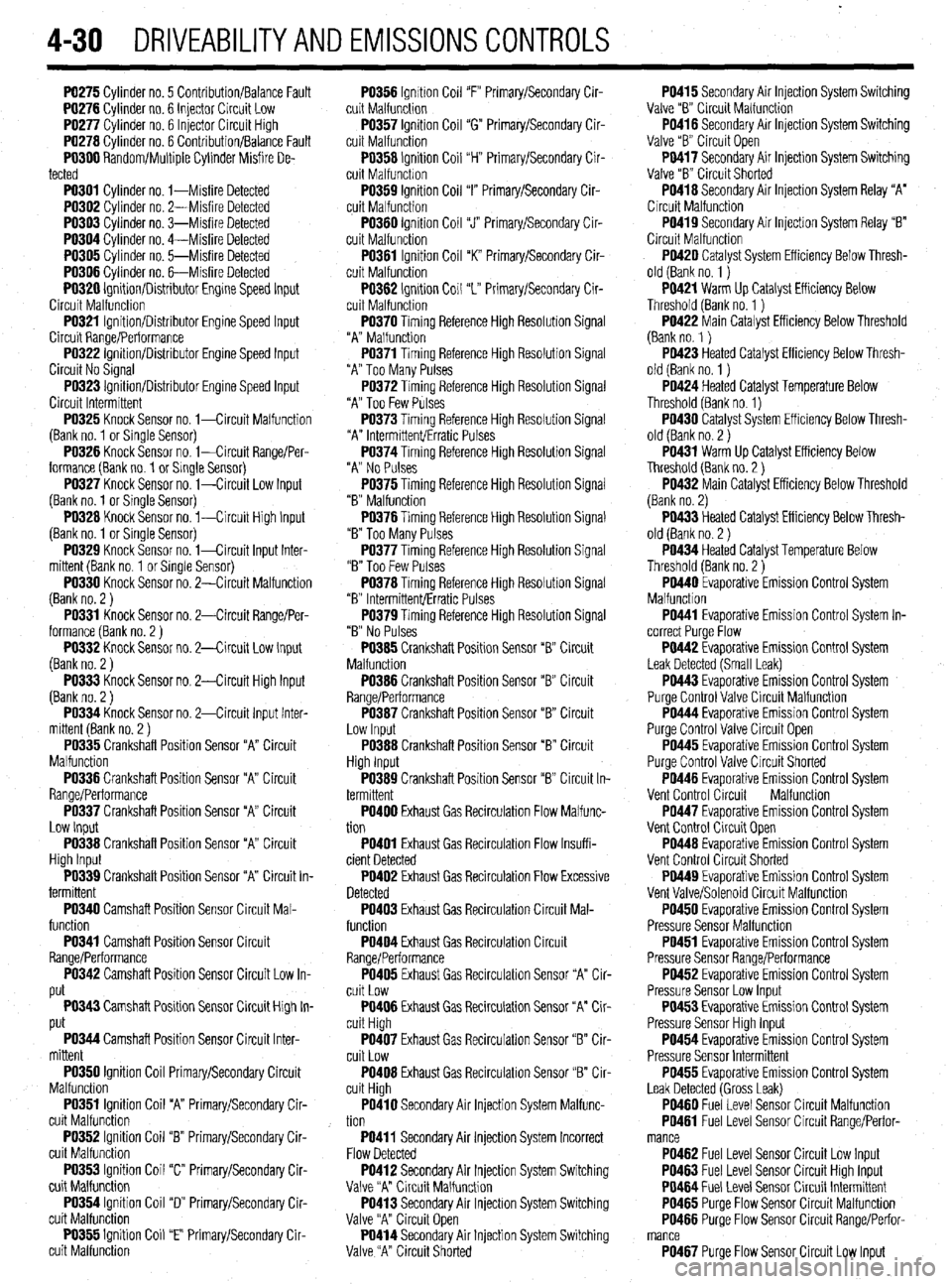
4-30 DRIVEABILITYAND EMISSIONS CONTROLS
PO275 Cvlinder no. 5 Contribution/Balance Fault
PO276 Cylinder no. 6 Injector Circuit Low
PO277 Cylinder no. 6 lniector Circuit High
PO278 Cylinder no. 6 Contribution/Balance Fault
PO300 Random/Multiple Cylinder Misfire De-
tected
PO301 Cylinder no. l-Misfire Detected
PO302 Cvlinder no 2-Misfire Detected
PO303 Cylinder no. 3-Misfire Detected
PO304 Cylinder no. 4-Misfire Detected
PO305 Cylinder no. +-Misfire Detected
PO306 Cylinder no. &-Misfire Detected
PO320 Ignition/Distributor Engine Speed Input
Circuit Malfunction
PO321 Ignition/Distributor Engine Speed Input
Circuit Range/Performance
PO322 Ignibon/Distributor Engine Speed Input
Circuit No Signal
PO323 Ignition/Distributor Engine Speed Input
Circuit Intermittent
PO325 Knock Sensor no. l-Circuit Malfunction
(Bank no. 1 or Single Sensor)
PO326 Knock Sensor no. l-Circuit Range/Per-
formance (Bank no. 1 or Srngle Sensor)
PO327 Knock Sensor no. l-Circuit Low Input
(Bank no. 1 or Single Sensor)
PO328 Knock Sensor no. l-Circuit High Input
(Bank no. 1 or Single Sensor)
PO329 Knock Sensor no. l-Circuit Input Inter-
mittent (Bank no. 1 or Smgle Sensor)
PO330 Knock Sensor no. 2-Circuit Malfunction
(Bank no. 2 )
PO331 Knock Sensor no. 2-Circuit Range/Per-
formance (Bank no. 2 )
PO332 Knock Sensor no. 2-Circuit Low Input
(Bank no. 2 )
PO333 Knock Sensor no. 2-Circuit High Input
(Bank no. 2 )
PO334 Knock Sensor no. 2-Circuit Input Inter-
mittent (Bank no. 2)
PO335 Crankshaft Position Sensor “A” Circuit
Malfunction
PO336 Crankshaft Position Sensor “A” Circuit
Range/Performance
PO337 Crankshaft Position Sensor “A” Circuit
Low Input
PO338 Crankshaft Position Sensor “A” Circuit
High Input
PO339 Crankshaft Position Sensor “A” Circuit In-
termittent
PO340 Camshaft Position Sensor Circuit Mal-
function
PO341 Camshaft Position Sensor Circuit
Range/Performance
PO342 Camshaft Position Sensor Circuit Low In-
put
PO343 Camshaft Position Sensor Circuit High In-
put
PO344 Camshaft Position Sensor Circuit Inter-
mittent
PO350 Ignition Coil Primary/Secondary Circuit
Malfunction
PO351 Ignition Coil “A” Primary/Secondary Cir-
cuit Malfunction
PO352 Ignition Coil “B” Primary/Secondary Cir-
cuit Malfunction
PO353 Ignition Coil “C” Primary/Secondary Cir-
cuit Malfunction
PO354 Ignition Coil “D” Primary/Secondary Cir-
cuit Malfunction
PO355 Ignition Coil “E” Primary/Secondary Cir-
cuit Malfunction PO356 Ignition Coil “F” Primary/Secondary Cir-
cuit Malfunction
PO357 Ignition Coil “G” Primary/Secondary Cir-
cuit Malfunction
PO358 Ignition Coil ‘Y-l” Primary/Secondary Cir-
cuit Malfunctron
PO359 Ignition Coil “I” Primary/Secondary Cir-
cuit Malfunction
PO360 Ignition Coil “J” Primary/Secondary Cir-
cuit Malfunction
PO361 Ignition Coil “K” Primary/Secondary Cir-
cuit Malfunction
PO362 Ignition Coil “L” Primary/Secondary Cir-
cuit Malfunction
PO370 Timing Reference High Resolution Signal
“A” Malfunction
PO371 Timing Reference High Resolution Signal
“A” Too Many Pulses
PO372 Timing Reference High Resolution Signal
“A” Too Few Pulses
PO373 Timing Reference High Resolution Signal
“A” Intermittent/Erratic Pulses
PO374 Timing Reference High Resolution Signal
“A” No Pulses
PO375 Timing Reference High Resolution Signal
“B” Malfunction
PO376 Timing Reference High Resolution Signal
“B” Too Many Pulses
PO377 Timing Reference High Resolution Signal
9” Too Few Pulses
PO378 Timing Reference High Resolution Signal
“B” Intermittent/Erratic Pulses
PO379 Timing Reference High Resolution Signal
“B” No Pulses
PO385 Crankshaft Position Sensor 9” Circuit
Malfunction
PO386 Crankshaft Position Sensor “B” Circuit
Range/Performance
PO387 Crankshaft Position Sensor ‘9” Circuit
Low Input
PO388 Crankshaft Position Sensor “B” Circuit
High Input
PO389 Crankshaft Position Sensor “B” Circuit In-
termittent
PO400 Exhaust Gas Recirculation Flow Malfunc-
tion
PO401 Exhaust Gas Recirculation Flow Insuffi-
cient Detected
PO402 Exhaust Gas Recirculation Flow Excessive
Detected
PO403 Exhaust Gas Recirculation Circuit Mal-
function
PO404 Exhaust Gas Recirculation Circuit
Range/Performance
PO405 Exhaust Gas Recirculation Sensor “A” Cir-
cuit Low
PO406 Exhaust Gas Recirculation Sensor “A” Cir-
cuit High
PO407 Exhaust Gas Recirculation Sensor “B” Cir-
cuit Low
PO408 Exhaust Gas Recirculation Sensor “B” Cir-
cuit High
PO410 Secondary Air Injection System Malfunc-
tion
PO411 Secondary Air Injection System Incorrect
Flow Detected
PO412 Secondary Air Injection System Switching
Valve “A” Circuit Malfunction
PO413 Secondary Air Injection System Switching
Valve “A” Circuit Open
PO414 Secondary Air Injection System Switching
Valve “A” Circuit Shorted PO415 Secondary Air Injection System Switching
Valve “B” Circuit Malfunction
PO416 Secondary Air Injection System Switching
Valve “B” Circuit Open
PO417 Secondary Air Injection System Switching
Valve “B” Circuit Shorted
PO418 Secondary Air Injection System Relay “A
Circuit Malfunction
PO419 Secondary Air Injection System Relay “B”
Circuit Malfunction
PO420 Catalyst System Efficiency Below Thresh-
old (Bank no. 1 )
PO421 Warm Up Catalyst Efficiency Below
Threshold (Bank no. 1 )
PO422 Main Catalyst Efficiency Below Threshold
(Bank no. 1 )
PO423 Heated Catalyst Efficiency Below Thresh-
old (Bank no. 1 )
PO424 Heated Catalyst Temperature Below
Threshold (Bank no. 1)
PO430 Catalyst System Efficiency Below Thresh-
old (Bank no. 2 )
PO431 Warm Up Catalyst Efficiency Below
Threshold (Bank no. 2 )
PO432 Main Catalyst Efficiency Below Threshold
(Bank no. 2)
PO433 Heated Catalyst Efficiency Below Thresh-
old (Bank no. 2 )
PO434 Heated Catalvst Temoerature Below
Threshold (Bank no. 2
j ’
PO440 Evaporative Emission Control System
Malfunction
PO441 Evaporative Emission Control System In-
correct Purge Flow
PO442 Evaporative Emission Control System
Leak Detected (Small Leak)
PO443 Evaporative Emission Control System
Purge Control Valve Circuit Malfunction
PO444 Evaporative Emission Control System
Purge Control Valve Circuit Open
PO445 Evaporative Emission Control System
Purge Control Valve Circuit Shorted
PO446 Evaporative Emission Control System
Vent Control Circuit Malfunction
PO447 Evaporative Emission Control System
Vent Control Circuit Open
PO448 Evaporative Emission Control System
Vent Control Circuit Shorted
PO449 Evaporative Emission Control System
Vent Valve/Solenoid Circuit Malfunction
PO450 Evaporative Emission Control System
Pressure Sensor Malfunction
PO451 Evaporative Emission Control System
Pressure Sensor Range/Performance
PO452 Evaporative Emission Control System
Pressure Sensor Low Input
PO453 Evaporative Emission Control System
Pressure Sensor High Input
PO454 Evaporative Emission Control System
Pressure Sensor Intermittent
PO455 Evaporative Emission Control System
Leak Detected (Gross Leak)
PO460 Fuel Level Sensor Circuit Malfunction
PO461 Fuel Level Sensor Circuit Range/Perfor-
mance
PO462 Fuel Level Sensor Circuit Low Input
PO463 Fuel Level Sensor Circuit High Input
PO464 Fuel Level Sensor Circuit Intermittent
PO465 Purge Flow Sensor Circuit Malfunction
PO466 Purge Flow Sensor Circuit Range/Perfor-
mance
PO467 Purge Flow Sensor Circuit Low Input
Page 174 of 408
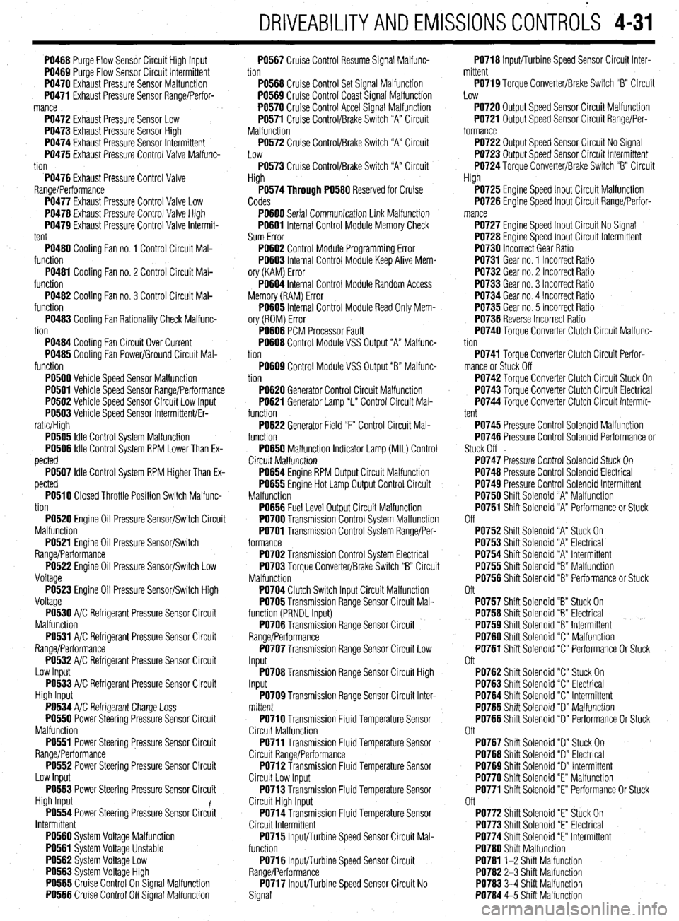
DRIVEABILITYAND EMISSIONSCONTROL-S 4-31
PO466 Purge Flow Sensor Circuit High Input
PO469 Purqe Flow Sensor Circuit Intermittent
PO470 Exhaust Pressure Sensor Malfunction
PO471 Exhaust Pressure Sensor Range/Perfor-
mance
PO472 Exhaust Pressure Sensor Low
PO473 Exhaust Pressure Sensor Hiah
PO474 Exhaust Pressure Sensor lnirmittent
PO475 Exhaust Pressure Control Valve Malfunc-
tion
PO476 Exhaust Pressure Control Valve
Range/Performance
PO477 Exhaust Pressure Control Valve Low
PO476 Exhaust Pressure Control Valve High
PO479 Exhaust Pressure Control Valve Intermit-
tent
PO460 Cooling Fan no 1 Control Circuit Mal-
function
PO461 Cooling Fan no. 2 Control Circuit Mal-
function
PO462 Cooling Fan no. 3 Control Circuit Mal-
function
PO463 Cooling Fan Rationality Check Malfunc-
tion
PO464 Cooling Fan Circuit Over Current
PO465 Cooling Fan Power/Ground Circuit Mal-
function
PO500 Vehicle Speed Sensor Malfunction
PO501 Vehicle Speed Sensor Range/Performance
PO502 Vehicle Speed Sensor Circuit Low Input
PO503 Vehicle Speed Sensor Intermittent/Er-
ratic/High
PO505 Idle Control System Malfunction
PO506 Idle Control System RPM Lower Than Ex-
pected
PO507 Idle Control System RPM Higher Than Ex-
pected
PO510 Closed Throttle Position Switch Malfunc-
tion
PO520 Engine Oil Pressure Sensor/Switch Circuit
Malfunction
PO521 Engine Oil Pressure Sensor/Switch
Range/Performance
PO522 Engine Oil Pressure Sensor/Switch Low
Voltage
PO523 Engine Oil Pressure Sensor/Switch High
Voltage
PO530 A/C Refrigerant Pressure Sensor Circuit
Malfunction
PO531 A/C Refrigerant Pressure Sensor Circuit
Range/Performance
PO532 A/C Refrigerant Pressure Sensor Circuit
Low Input
PO533 A/C Refrigerant Pressure Sensor Circuit
High Input
PO534 A/C Refrigerant Charge Loss
PO550 Power Steering Pressure Sensor Circuit
Malfunction
PO551 Power Steering Pressure Sensor Circuit
Range/Performance
PO552 Power Steering Pressure Sensor Circuit
Low Input
PO553 Power Steering Pressure Sensor Circuit
High Input
PO554 Power Steering Pressure Sensor Circiit
Intermittent
PO560 System Voltage Malfunction
PO561 System Voltage Unstable
PO562 System Voltage Low
PO563 Svstem Voltaoe Hlah
PO565 Ciuise Control On%ignal Malfunction
PO566 Cruise Control Off Signal Malfunction PO567 Cruise Control Resume Signal Malfunc-
tion
PO566 Cruise Control Set Signal Malfunction
PO569 Cruise Control Coast Signal Malfunction
PO570 Cruise Control Accel Signal Malfunction
PO571 Cruise Control/Brake Switch “A” Circuit
Malfunction
PO572 Cruise Control/Brake Switch “A” Circuit
Low
PO573 Cruise Control/Brake Switch “A” Circuit
High
P0574Through PO560 Reserved for Cruise
Codes
PO600 Serial Communication Link Malfunction
PO601 Internal Control Module Memory Check
Sum Error
PO602 Control Module Programming Error
PO603 Internal Control Module Keep Alive Mem-
ory (KAM) Error
PO604 Internal Control Module Random Access
Memory (RAM) Error
PO605 Internal Control Module Read Only Mem-
ory (ROM) Error
PO606 PCM Processor Fault
PO606 Control Module VSS Output “A” Malfunc-
tion
PO609 Control Module VSS Output “6” Malfunc-
tion
PO620 Generator Control Circuit Malfunction
PO621 Generator Lamp “L” Control Circuit Mal-
function
PO622 Generator Field “F” Control Circuit Mal-
function
PO650 Malfunction Indicator Lamp (MIL) Control
Circuit Malfunctron
PO654 Engine RPM Output Circuit Malfunction
PO655 Engine Hot Lamp Output Control Circuit
Malfunction
PO656 Fuel Level Output Circuit Malfunction
PO700 Transmission Control System Malfunction
PO701 Transmission Control System Range/Per-
formance
PO702 Transmission Control System Electrical
PO703 Torque Converter/Brake Switch “B” Circuit
Malfunction
PO704 Clutch Switch Input Circuit Malfunction
PO705 Transmission Range Sensor Circuit Mal-
function (PRNDL Input)
PO706 Transmission Range Sensor Circuit
Range/Performance
PO707 Transmission Range Sensor Circuit Low
Input
PO706 Transmission Range Sensor Circuit High
Input
PO709 Transmission Range Sensor Circuit Inter-
mittent
PO710 Transmission FluId Temperature Sensor
Circuit Malfunction
PO711 Transmission Fluid Temperature Sensor
Circuit Range/Performance
PO712 Transmission Fluid Temperature Sensor
Circuit Low Input
PO713 Transmission Fluid Temperature Sensor
Circuit High Input
PO714 Transmission Fluid Temperature Sensor
Circuit Intermittent
PO715 Input/Turbine Speed Sensor Circuit Mal-
function
PO716 Input/Turbine Speed Sensor Circuit
Range/Performance
PO717 InpWurbine Speed Sensor Circuit No
Signal PO716 Inputflurbine Speed Sensor Circuit Inter-
mittent
PO719 Torque Converter/Brake Switch “B” Circuit
Low
PO720 Output Speed Sensor Circuit Malfunction
PO721 Output Speed Sensor Circuit Range/Per-
formance
PO722 Output Speed Sensor Circuit No Signal
PO723 Output Speed Sensor Circuit Intermittent
PO724 Toraue Converter/Brake Switch “B” Circuit
High
PO725 Engine Speed Input Circuit Malfunction
PO726 Engine Speed Input Circuit Range/Perfor-
PO727 Engine Speed Input Circuit No Signal
PO726 Engine Speed Input Circuit Intermittent
PO730 Incorrect Gear Ratio
PO731 Gear no. 1 Incorrect Ratio
PO732 Gear no. 2 Incorrect Ratio
PO733 Gear no. 3 Incorrect Ratio
PO734 Gear no 4 Incorrect Ratio
PO735 Gear no. 5 Incorrect Ratio
PO736 Reverse Incorrect Ratio
PO740 Torque Converter Clutch Circuit Malfunc-
tion
PO741 Torque Converter Clutch Circuit Perfor-
mance or Stuck Off
PO742 Torque Converter Clutch Circuit Stuck On
PO743 Torque Converter Clutch Circuit Electrical
PO744 Torque Converter Clutch Circuit Intermit-
tent
PO745 Pressure Control Solenoid Malfunction
PO746 Pressure Control Solenoid Performance or
Stuck Off
PO747 Pressure Control Solenoid Stuck On
PO746 Pressure Control Solenoid Electrical
PO749 Pressure Control Solenoid Intermittent
PO750 Shift Solenoid “A” Malfunction
PO751 Shift Solenoid “A” Performance or Stuck
Off
PO752 Shift Solenoid “A” Stuck On
PO753 Shift Solenoid “A” Electrical
PO754 Shift Solenoid “A” Intermittent
PO755 Shift Solenoid “8 Malfunction
PO756 Shift Solenoid “B” Performance or Stuck
Oft
PO757 Shift Solenoid “B” Stuck On
PO756 Shift Solenoid “6” Electrical
PO759 Shift Solenoid “8” Intermittent
PO760 Shift Solenoid “C” Malfunction
PO761 Shift Solenoid “C” Performance Or Stuck
Oft
PO762 Shift Solenoid “C” Stuck On
PO763 Shift Solenoid “C” Electrical
PO764 Shift Solenoid “C” Intermittent
PO765 Shift Solenoid “D” Malfunction
PO766 Shift Solenoid “D” Performance Or Stuck
Oft
PO767 Shift Solenoid “D” Stuck On
PO766 Shift Solenoid “D” Electrical
PO769 Shift Solenoid “D” Intermittent
PO770 Shift Solenoid “E” Malfunction
PO771 Shift Solenoid “E” Performance Or Stuck
Off
PO772 Shift Solenoid “E” Stuck On
PO773 Shift Solenoid “E” Electrical
PO774 Shift Solenoid “E” Intermittent
PO760 Shift Malfunction
PO761 l-2 Shift Malfunction
PO762 2-3 Shift Malfunction
PO763 3-4 Shift Malfunction
PO764 4-5 Shift Malfunction
Page 175 of 408
4-32 DRIVEABILITYAND EMISSIONS CONTROLS
PO785 Shift/Timing Solenoid Malfunction
PO786 Shift/Timing Solenoid Range/Performance
PO787 Shift/Timing Solenoid Low
PO788 Shift/Timing Solenord High
PO789 Shift/Timing Solenoid Intermittent
PO790 Normal/Performance Switch Circuit Mal-
function
PO801 Reverse Inhibit Control Circuit Malfunc-
tion
PO803 l-4 Upshift (Skip Shift) Solenoid Control
Circuit Malfunction
PO804 l-4 Upshift (Skip Shift) Lamp Control
Circuit Malfunction
PllOO Induction Control Motor Position Sensor
Fault
PI101 Traction Control Vacuum Solenoid Circuit
Fault
Pl102 Traction Control Ventilation Solenoid Cir-
cuit Fault P1294 Target Idle Speed Not Reached
P1295 No 5-Volt Supply To TP Sensor
P1296 No 5-Volt Supply To MAP Sensor
P1297 No Change In MAP From Start To Run
PI300 Ignition Timing Adjustment Circuit
Pl390 Timing Belt Skipped One Tooth Or More
Pl391 Intermittent Loss Of CMP Or CKP Sensor
Signals P1495 EVAP Ventilation Solenoid Circurt Fault
P1496 5-Volt Supply Output Too Low
Pl500 Generator FR Terminal Circuit Fault
Pl600 PCM-TCM Serial Communication Link
Circuit Fault
Pl400 Manifold Differential Pressure Sensor
Fault P1696 PCM Failure- EEPROM Write Denied
Pl715 No CCD Messages From TCM
Pl750 TCM Pulse Generator Circuit Fault
Pl791 Pressure Control, Shift Control, TCC So-
lenoid Fault
P1443 EVAP Purge Control Solenoid “2” Circuit
Fault P1899 PCM ECT Level Signal to TCM Circuit
Fault
P1486 EVAP Leak Monitor Pinched Hose De-
tected
P1989 High Speed Condenser Fan Control Relay
Fault
P1487 High Speed Radiator Fan Control Relay
Circuit Fault
Pl490 Low Speed Fan Control Relay Fault
P1492 Battery Temperature Sensor High Voltage
P1494 EVAP Ventilation Switch Or Mechanical
FLASH OUT CODE LIST
# See Figures
93, 94, 95, and 96
Fault PI105 Fuel Pressure Solenoid Circuit Fault
Code
Output pattern
(for voltmeter) Cause
P1702
Shorted throttle position sensor cil
cuit
MATOOSE
Pl701
Open throttle position sensor circuii
A!iATW5F
p1704 -
Throttle position sensor malfunc-
tion
Improperly adjusted throttle posi-
ASATmH tion sensor
PO71 2
Open fluid temperature sensor cir-
u 1 cuit
ASAT
PO71 3
Shorted fluid temperature sensor
circuit
ASATOOU
Pl709
I I Open kickdown servo switch circuit
Shorted kickdown servo switch cir-
cuit
A5ATOOSK
Remedy
o Check the throttle position sen-
sor connector
o check the throttle position sen-
sor itself
o Check the closed throttle posi-
tion switch
o Check the throttle position sen-
sor wiring harness
o Check the wiring between ECM
and throttle position sensor
o Fluid temperature sensor con-
nector inspection
o Fluid temperature sensor inspec-
tion
o Fluid temperature sensor wiring
harness inspection
o Check the kickdown servo switch
connector
o Check the kickdown servo switch
o Checkthe kickdown servo switch
wiring harness
Fig. 93 Mitsubishi flash out DTC's, 1 of 4-Type 4 (DBD II) Codes
Page 176 of 408
DRIVEABILITYAND EMISSIONS CONTROLS 4-33
Code
PO727
P1714
PO71 7
PO722
PO707
PO708
PO752
PO753
PO757
PO758
PO747
PO748 Output pattern
(for voltmeter) Cause Remedy
A5ATW51
Open ignition pulse pickup cable
circuit o Check the ignition pulse signal
line
o Checkthe wiring between ECM
and ignisiton system
Short-circuited or improperly ad-
o Check the closed throttle posi-
justed closed throttle position switch
tion switch connector
ASATOOSM o Check the closed throttle posi-
tion switch itself
o Adjust the closed throttle posi-
tion switch
o Check the closed throttle posi-
tion switch wiring harness
Open-circuited pulse generator A o Check the pulse generator A and
pulse generator 6
ASATOOSN o Check the vehicle speed reed
Open-circuited pulse generator B switch (for chattering)
o CheckthepulsegeneratorA and
A5ATOO50 B wiring harness
m No input signal o Checkthe transaxle range switch
o Check the transaxle range wir-
A5ATOO.52 ing harness
o Check the manual control cable
ASATOOSP
ASATOO5Q
A5ATOOSS
I Open shift control solenoid vave A
circuit
Shorted shift control solenoid valve
Open shift control solenoid valve B
Short shift control solenoid valve B
circuit o Check the solenoid valve con-
nector
o Check the shift control solenoid
valve A
o Check the shift control solenoid
valve A wiring harness
o Check the shift control solenoid
valve connector
o Check the shift control solenoid
valve B wiring harness
o Check the shift control solenoid
valve B
Open pressure control solenoid
valve circuit o Check the pressure control sole-
noid valve
o Check the pressure control sole-
noid valve wiring harness
ASATOOSJ
I
89446928
i9. 94 Mitsubishi flash out DTC’s, 2 of 4-Type 4 (DBD II) Codes
Page 177 of 408
.
4-34 DRIVEABILITYAND EMISSIONS CONTROLS
Open circuit in damper clutch con-
trol solenoid valve
Short circuit in damper clutch con-
trol solenoid valve
Defect in the damper clutch sys- o Inspection of solenoid valve
connector
o Individual inspection of damper
clutch control solenoid valve
o Check the damper clutch control
solenoid valve wiring harness
o Chck the TCM
o Inspection of damper clutch hy-
draulic system
PO732 Shifting to first gear does not heckthe pulse generator A and
match the engine speed pulse generator B connector
o Check the pulse generator A and
Shifting to second gear does puls generator B
not match the engine speed o Checkthe one way clutch or rear
clutch
o Check the pulse generator wir-
ing harness
ASATAOSC o Kickdown brake slippage
PO733 Shifting to third gear does not o Check the rear clutch or control
match the engine speed system
o Check the pulse generator A and
pulse generator B connector
o Check the pulse generator A and
pulse generator B
o Checkthe pulse generatorwiring
harness
o Check the rear clutch slippage or
control system
A5ATA05D o Check the front clutch slippage
or control system
PO734
Shifting to fourth geardoes not match o Check the pulse generator A
the engine speed and B connector
o Check the pulse generator A
and B
o Kickdown brake slippage
o Check the end clutch or control
system
o Check the pulse generator wir-
ASATA05E ing harness
Normal
J
89446 :ig. 95 Mitsubishi flash out DTC’s, 3 of 4-Type 4 (OBD II) Codes
Page 178 of 408
.
DRIVEABILITYAND EMISSIONS CONTROLS 4-35
FAIL-SAFE ITEM
A5ATOO5P 1
Open-circuited pulse Locked in third (D) or When code No.0722 is
generator B second (2,L) generated fourth time
Open-circuited or
shorted shift control
solenoid valve A Lock in third When code No.0752 or
0753 is generated fourth
time
PO753 m
MAT0050 1
Open-circuited or
shorted shift control
solenoid valve B
PO758
PO731
PO732
A5ATAO58
A5ATAO5C
PO733
A5ATAOSD
PO734
A5ATAOSE
Gear shifting does not
match the engine speec Fail-safe Note
(relation to diagnostic
1 trouble code)
Locked in third (D) or When code No.071 7 is
second (2,L) generated fourth time
I
Lock in third gear
Locked in third (D) or When code No.0747
second (2,L) or 0748 is generated
fourth time
Locked in third (D) or When either code
second (2,L) No.O731,0732,0733 or
0734 is generated fourth
time
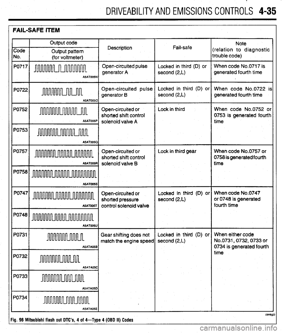
ig. 96 Mitsubishi flash out DTC’s, 4 of 4-Type 4 (060 II) Codes
Page 179 of 408
4-36 DRIVEABILITYAND EMISSIONS CONTROLS
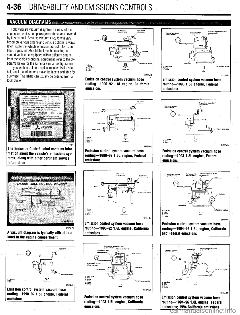
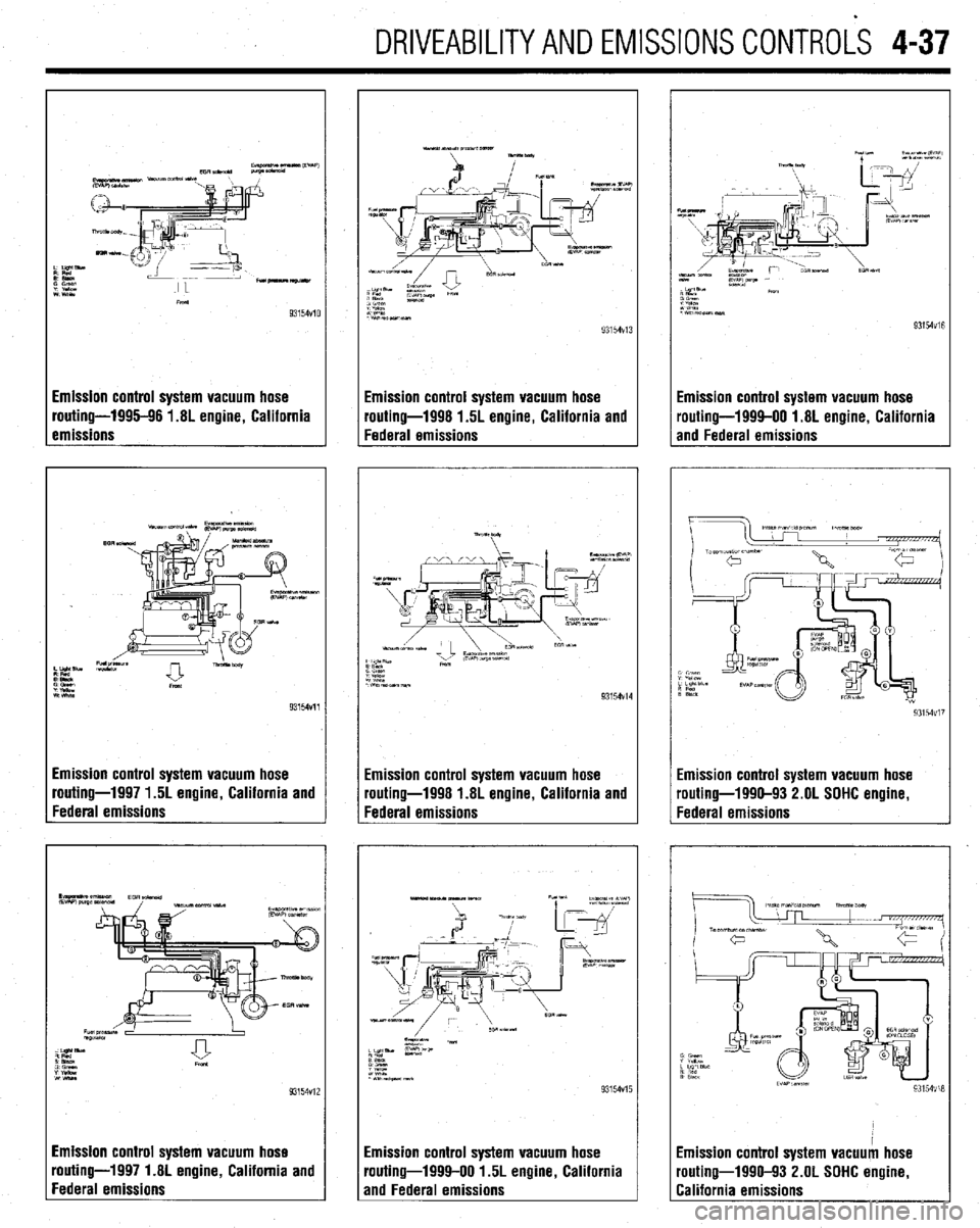
Following are vacuum magrams for most of the
engine and emissions package combinations covered
by this manual Because vacuum circuits will vary
based on various engine and vehicle options, always
refer first to the vehicle emission control Information
label, if present. Should the label be missing, or
should vehicle be equipped with a different engine
from the vehicle’s original equipment, refer to the di-
agrams below for the same or similar configuration.
If you wish to obtain a replacement emissions la-
bel, most manufacturers make the labels available for
lurchase. The labels can usually be ordered from a
ocal dealer.
A vacuum diagram is typically affixed to a
label in the engine compartment
93154voI Emission control system vacuum hose
routing-1990-92 1.5L engine, Federal
emissions
93154vul Emission control system vacuum hose
routing-1990-92 1.5L engine, California
emissions
Emission control system vacuum hose
routing-1990-92 1.6L engine, Federal
emissions
Emission control system vacuum hose
routing-1990-92 1.6L engine, California
emissions
Emission control system vacuum hose
routing-1993 1.5L engine, California
emissions
I
r
I I
1 I
Emission control system vacuum hose
routing-1993 1.5L engine, Federal
emissions
-
Emission control system vacuum hose
‘outing-1993 1.6L engine, Federal
rmissions
93154vo8 Emission control system vacuum hose
routing-1994-96 1.5L engine. California
and Federal emissions -
routing-1994-96 1.8L engine, Federal
emissions; 1994 California emissions
Page 180 of 408
DRIVEABILITYAND EMISSIONS CONTROLi 4-37
,i
Ii *ul--
hm
93154VlO
Emission control system vacuum hose
routing-1995-96 1.8L engine, California
emissions
93154Vll
Emission control system vacuum hose
routing-1997 1.5L engine, California and
Federal emissions
Emission control system vacuum hose
‘outing-1997 1.8L engine, California and
Federal emissions Emission control system vacuum hose
routing-1998 1.5L engine, California and
Federal emissions
Emission control system vacuum hose
routing-1998 1.8L engine, California and
Federal emissions
93154v15
Emission control system vacuum hose
fouting-1999-00 1.5L engine, California
%nd Federal emissions Emission control system vacuum hose
routing-1999-00 1.8L engine, California
and Federal emissions
93154v17
Emission control system vacuum hose
routing-1990-93 2.OL SOHC engine,
Federal emissions
Emission control system vacuum hose
routing-1990-93 2.OL SOHC engine,
California emissions