MITSUBISHI DIAMANTE 1900 Repair Manual
Manufacturer: MITSUBISHI, Model Year: 1900, Model line: DIAMANTE, Model: MITSUBISHI DIAMANTE 1900Pages: 408, PDF Size: 71.03 MB
Page 211 of 408
6-8 CHASSIS ELECTRICAL
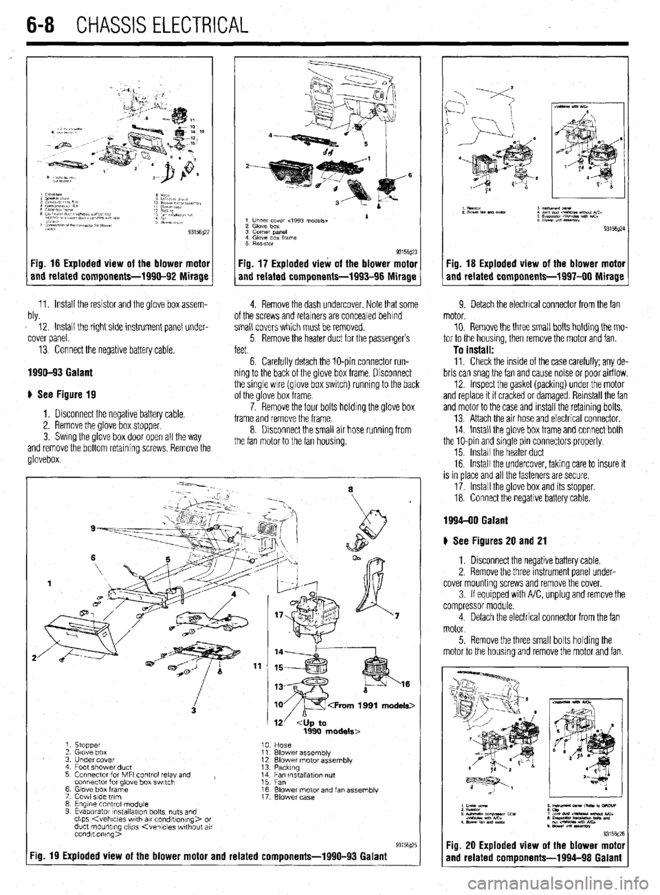
Fig. 16 Exploded view of the blower motor
and related components-1990-92 Mirage
11. Install the resistor and the glove box assem- W 12. Install the right side instrument panel under-
cover panel.
13. Connect the negative battery cable.
1990-93 Galant
# See Figure 19
1. Disconnect the negative battery cable.
2. Remove the glove box stopper.
3. Swing the glove box door open all the way
and remove the bottom retainina screws. Remove the
glovebox
1 Under cover 4993 models, 1
2 Glove box
3 corner pane,
4 Glove box frame
5 RBSlStOr
93156~23
Fig. 17 Exploded view of the blower motor
and related components-1993-96 Mirage
4. Remove the dash undercover. Note that some 9. Detach the electrical connector from the fan
ot the screws and retainers are concealed behind
small covers which must be removed.
5 Remove the heater duct for the passenger’s
feet.
6. Carefully detach the lo-pin connector run-
ning to the back of the glove box frame. Disconnect
the single wire (glove box switch) running to the back
of the glove box frame.
7. Remove the four bolts holding the glove box
frame and remove the frame.
8. Disconnect the small air hose running from
the fan motor to the fan housing. motor.
10. Remove the three small bolts holding the mo-
tor to the housing, then remove the motor and fan.
To install: 11. Check the inside of the case carefully: any de-
bris can snag the fan and cause noise or poor airflow.
12. Inspect the gasket (packing) under the motor
and replace it if cracked or damaged. Reinstall the fan
and motor to the case and Install the retaining bolts.
13. Attach the air hose and electrical connector.
14. Install the glove box frame and connect both
the lo-pin and sinqle pin connectors properly.
15. Install the heater duct
16. Install the undercover, taking care to insure it
is in place and all the fasteners are secure.
17. Install the glove box and its stopper.
18. Connect the negative battery cable.
:ig. 19 Exploded view of the blower motor and related components-1990-93 Galant
1. stopper
‘2 Glove box
3 Under cover
4 Foot shower duct
5 Connector for MFI control relay and ,
connector for glove box swtch
6 Glove box frame
7 Cowl side trim
8 Engine control module
9 Evaporator lnstallatlon bolts, nuts and
clips
duct mounting clips Kvehlcles wthout air
condltionlng>
Fig. 18 Exploded view of the blower motor
and related components-1997-00 Mirage
--.
8
12’
Blower assemblv
Blower motor assembly
Packtng
;;c, tnstallatlon nut
Blower motor and fan assembly
Blower case
1994-00 Galant
) See Figures 20 and 21
1. Disconnect the negative battery cable.
2. Remove the three instrument panel under-
cover mounting screws and remove the cover.
3 If equipped with A/C, unplug and remove the
compressor module.
4. Detach the electrical connector from the fan
motor.
5. Remove the three small bolts holding the
motor to the housing and remove the motor and fan.
; y&M 5 m- M ,RC m .3RcuP
3 lulomafs corn-r ECU :2%brtr-Mbi&C>
.“eM *nn mi
1 slmhn.m”m,n 8 ~y~tipJ*-m-=%9 md
S sa*n”nlUSW
931561
Fig. 20 Exploded view of the blower mote
and related comoonents-1994-98 Galan
Page 212 of 408
CHASSIS ELECtRldAL 6-9
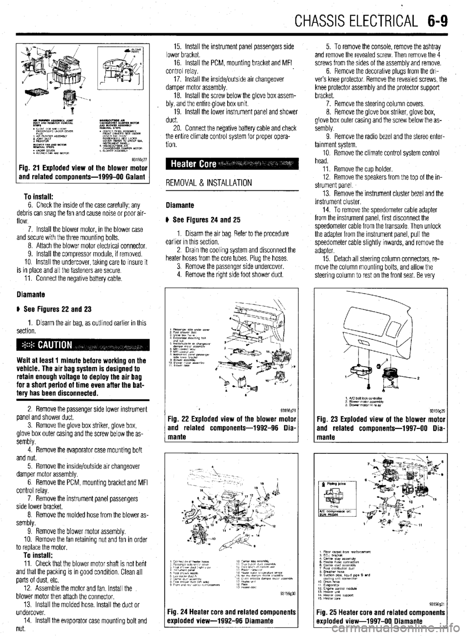
93156g27 Fig. 21 Exploded view of the blower motor
and related components-1999-00 Galant
To install:
6. Check the inside of the case carefully; any
debris can snag the fan and cause noise or poor air-
flow.
7. Install the blower motor, in the blower case
and secure with the three mounting bolts,
8. Attach the blower motor electrlcal connector,
9. Install the compressor module, if removed.
10. Install the undercover, takmg care to insure it
is in place and all the fasteners are secure.
11. Connect the negative battery cable.
Diamante
u See Figures 22 and 23
1. Disarm the air bag, as outlined earlier in this
section.
Wait at least 1 minute before working on the
vehicle. The air bag system is designed to
retain enough voltage to deploy the air bag
for a short period of time even after the bat-
tery has been disconnected.
2. Remove the passenger side lower instrument
panel and shower duct,
3. Remove the glove box striker, glove box,
glove box outer casing and the screw below the as-
sembly.
4. Remove the evaporator case mounting bolt
and nut.
5. Remove the inside/outside air changeover
damper motor assembly.
6 Remove the PCM, mounting bracket and MFI
control relay.
7. Remove the instrument panel passengers
side lower bracket.
8. Remove the molded hose from the blower as-
sembly.
9. Remove the blower motor assembly.
10. Remove the fan retaining nut and fan in order
to replace the motor,
To install: 11. Check that the blower motor shaft is not bent
and that the packing is in good condition, Clean all
parts of dust, etc.
12. Assemble the motor and fan. Install the
blower motor then attach the connector.
13. Install the molded hose. Install the duct or
undercover.
14. Install the evaporator case mounting bolt and
nut. 15. Install the instrument panel passengers side
lower bracket.
16. Install the PCM, mounting bracket and MFI
control relay.
17. Install the inside/outside air changeover
damper motor assembly.
18. Install the screw below the glove box assem-
bly, and the entire glove box unit.
19. Install the lower instrument panel and shower
duct.
20. Connect the negative battery cable and check
the entire climate control system for proper opera-
tion.
REMOVAL & INSTALLATION
Diamante
u See Figures 24
and 25
1. Disarm the air bag Refer to the procedure
earlier in this section.
2. Dram the cooling system and disconnect the
heater hoses from the core tubes. Plug the hoses.
3. Remove the passenger side undercover.
4. Remove the right side foot shower duct. 5. To remove the console, remove the ashtray
and remove the revealed screw. Then remove the 4
screws from the sides of the assembly and remove.
6. Remove the decorative plugs from the drl-
ver’s knee protector. Remove the revealed screws, the
knee protector assembly and the protector support
bracket.
7. Remove the steering column covers.
8. Remove the glove box striker, glove box,
glove box outer casing and the screw below the as-
sembly.
9. Remove the radio bezel and the stereo enter-
tainment system.
10. Remove the climate control system control
head.
11. Remove the cup holder.
12. Remove the speakers from the top of the in-
strument panel.
13. Remove the instrument cluster bezel and the
instrument cluster.
14. To remove the speedometer cable adapter
from the instrument panel, first disconnect the
speedometer cable from the transaxle. Then unlock
the adapter from the instrument panel, pull the
speedometer cable slightly inwards, and remove the
adapter
15. Detach all steering column connectors, re-
move the column mounting bolts, and allow the
steering column to rest on the front seat. Be very
Fig. 23 Exploded view of the blower motor
and related components-1997-00 Dia-
Fig. 25 Heater core and related components
exploded view-1997-00 Diamante
Page 213 of 408
640 CHASSIS ELECTRICAL
careful not to allow anything to come in contact with
the air bag unit.
16. Remove the glove box lamp assembly.
17. Remove the remaining instrument panel
mounting screws and remove the instrument panel
from the vehicle.
18. Remove the left side foot shower ductwork,
lap cooler duct and center duct.
19. Remove the front and center reinforcements
and center stay assembly.
20. Remove the air distribution duct assembly.
21. Detach all connectors from heater-box-
mounted items.
22. Remove the heater box mounting screws and
nut, then remove the unit from the vehicle.
23. Disassemble on a workbench. Remove the
heater core from the heater case.
To install:
24. Thoroughly clean and dry the inside of the
case and install the heater core and all related parts.
25. Install the heater unit to the vehicle and install
the mounting screws and nut. Be sure the evaporator
case and heater case are fitted together properly. At-
tach all connectors to heater-box-mounted items.
26. Install the air distribution duct assembly. In-
stall the front and center reinforcements and center
stay assembly.
27. Install the center duct, lap cooler duct and left
side foot shower duct.
28. Install the instrument panel and mounting
screws.
29. Install the glove box lamp assembly.
30. Secure the steering column and attach all
steering column connectors.
31. Install the speedometer cable adapter to the
instrument panel.
32. Install the instrument cluster and the instru-
ment cluster bezel.
33. Install the speakers to the top of the instru-
ment panel.
34. Install the cup holder.
35. Install the climate control system control
head.
36. Install the stereo entertainment system and
bezel.
37. Install the screw below the glove box assem-
bly, and the entire glove box unit.
38. Install the steering column covers.
39. Install the knee protector support bracket, the
protector and the decorative plugs.
40. Install the console and the ashtray. 41. Install the right side foot shower duct.
42. Install the passenger side undercover.
43. Connect the heater hoses to the core tubes.
44. Fill the cooling system.
45. Connect the negative battery cable and check
the entire climate control system for proper operation
and leaks.
Galant
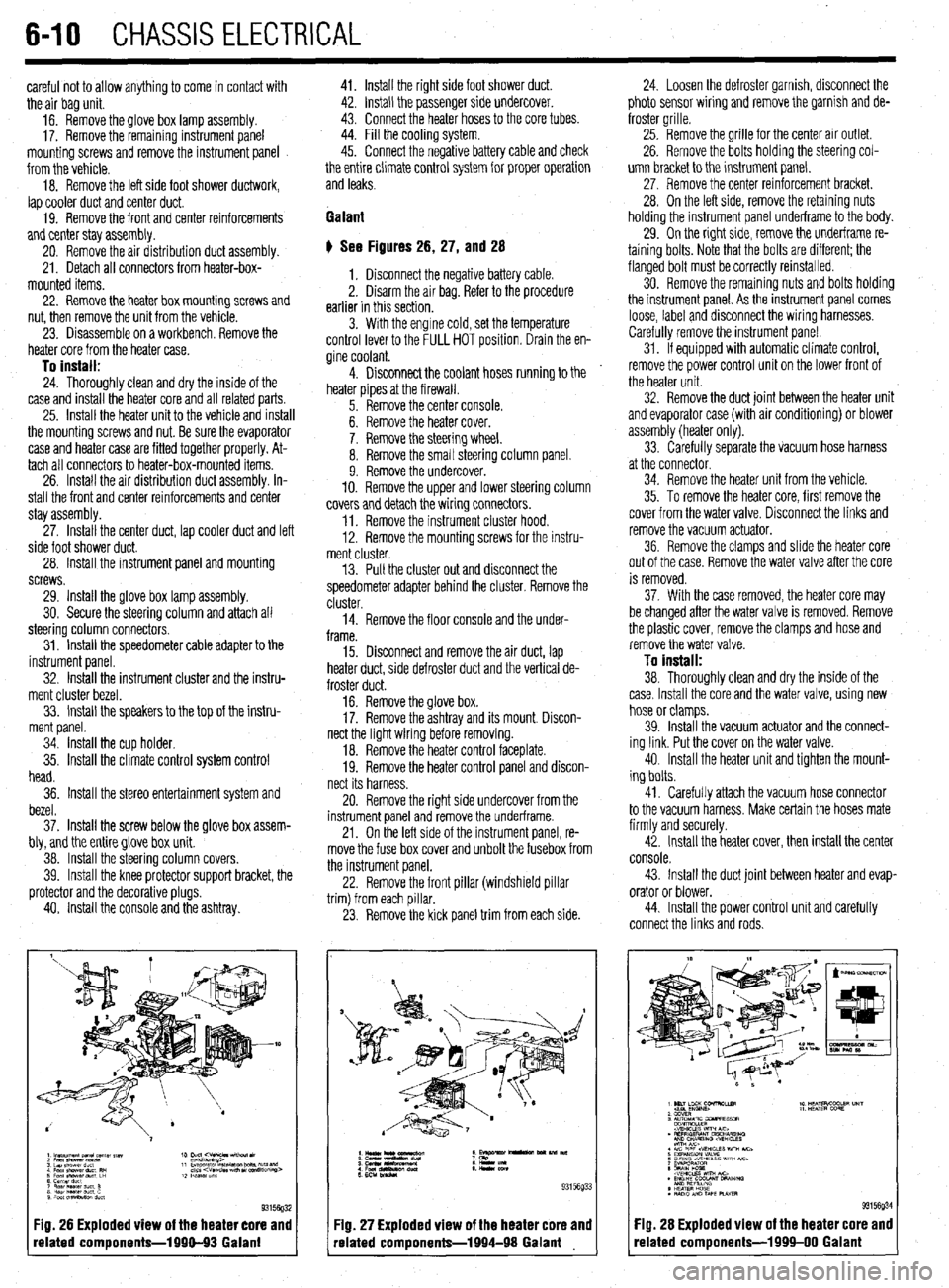
# See Figures 26, 27, and 28
1. Disconnect the negative battery cable.
2. Disarm the air bag. Refer to the procedure
earlier in this section.
3. With the engine cold, set the temperature
control lever to the FULL HOT position. Drain the en-
gine coolant.
4. Disconnect the coolant hoses running to the
heater pipes at the firewall.
5. Remove the center console.
6. Remove the heater cover.
7. Remove the steering wheel.
8. Remove the small steering column panel.
9. Remove the undercover.
10. Remove the upper and lower steering column
covers and detach the wiring connectors.
11. Remove the instrument cluster hood.
12. Remove the mounting screws for the instru-
ment cluster.
13. Pull the cluster out and disconnect the
speedometer adapter behind the cluster. Remove the
cluster.
14. Remove the floor console and the under-
frame.
15. Disconnect and remove the air duct, lap
heater duct, side defroster duct and the vertical de-
froster duct.
16. Remove the glove box.
17. Remove the ashtray and its mount. Discon-
nect the light wiring before removing.
18. Remove the heater control faceplate.
19. Remove the heater control panel and discon-
nect its harness.
20. Remove the right side undercover from the
instrument panel and remove the underframe.
21. On the left side of the instrument panel, re-
move the fuse box cover and unbolt the fusebox from
the instrument panel.
22. Remove the front pillar (windshield pillar
trim) from each pillar.
23. Remove the kick panel trim from each side.
Fig. 26 Exploded view of the heater core and
related components-1990-93 Galant
:IQ. 27 Exploded view of the heater core and
-elated components-1994-98 Galant 24. Loosen the defroster garnish, disconnect the
photo sensor wiring and remove the garnish and de-
froster grille.
25. Remove the grille for the center air outlet.
26. Remove the bolts holding the steering col-
umn bracket to the instrument panel.
27, Remove the center reinforcement bracket.
28. On the left side, remove the retaining nuts
holding the instrument panel underframe to the body.
29. On the right side, remove the underframe re-
taining bolts. Note that the bolts are different; the
flanged bolt must be correctly reinstalled.
30. Remove the remaining nuts and bolts holding
the instrument panel. As the instrument panel comes
loose, label and disconnect the wiring harnesses.
Carefully remove the instrument panel.
31. If equipped with automatic climate control,
remove the power control unit on the lower front of
the heater unit.
32. Remove the duct joint between the heater unit
and evaporator case (with air conditioning) or blower
assembly (heater only).
33. Carefully separate the vacuum hose harness
at the connector.
34. Remove the heater unit from the vehicle.
35. To remove the heater core, first remove the
cover from the water valve. Disconnect the links and
remove the vacuum actuator.
36. Remove the clamps and slide the heater core
out of the case. Remove the water valve after the core
is removed.
37. With the case removed, the heater core may
be changed after the water valve is removed. Remove
the plastic cover, remove the clamps and hose and
remove the water valve.
To install:
38. Thoroughly clean and dry the inside of the
case. Install the core and the water valve, using new
hose or clamps.
39. Install the vacuum actuator and the connect-
ing link. Put the cover on the water valve.
40. Install the heater unit and tighten the mount-
ing bolts.
41. Carefully attach the vacuum hose connector
to the vacuum harness. Make certain the hoses mate
firmly and securely.
42. Install the heater cover, then install the center
console.
43. Install the duct joint between heater and evap-
orator or blower.
44. Install the power control unit and carefully
connect the links and rods.
Fig. 28 Exploded view of the heater core and
related components-1999-00 Galant
Page 214 of 408
CHASSIS ELECTRICAL 6-11
45. Install the heater hoses under the hood.
46. Install the mstrument panel by reversing its
removal procedure.
47. Install the center console.
48. install the upper and lower steering column
covers.
49. Install the center panel undercover.
50. Install the small column panel.
51. Install the steering wheel.
52. Fill the cooling system.
53. Connect the negative battery cable and check
the entire climate control system for proper operation
and leaks.
Mirage
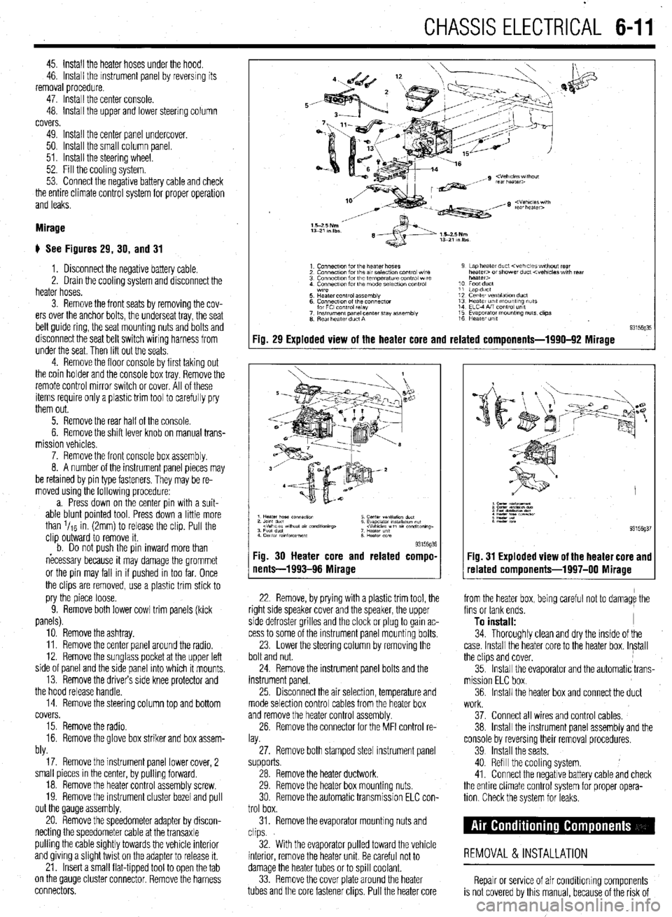
# See Figures 29, 30, and 31
1. Disconnect the negative battery cable.
2. Drain the cooling system and disconnect the
heater hoses.
3. Remove the front seats by removing the cov-
ers over the anchor bolts, the underseat tray, the seat
belt guide ring, the seat mounting nuts and bolts and
disconnect the seat belt switch wiring harness from
under the seat. Then lift out the seats
4. Remove the floor console by first taking out
the coin holder and the console box tray. Remove the
remote control mirror switch or cover. All of these
items require only a plastic trim tool to carefully pry
them out.
5. Remove the rear half of the console.
6. Remove the shift lever knob on manual trans-
mission vehicles.
7. Remove the front console box assembly.
8. A number of the instrument panel pieces may
be retamed by pin type fasteners. They may be re-
moved using the following procedure:
a. Press down on the center pin with a suit-
able blunt pointed tool. Press down a little more
than l/re in. (2mm) to release the clip. Pull the
clip outward to remove it.
b. Do not oush the oin inward more than
necessary because it may damage the grommet
or the pin may fall in if pushed in too far. Once
the clips are removed, use a plastic trim stick to
pry the piece loose.
9. Remove both lower cowl trim panels (kick
panels).
10. Remove the ashtray.
11. Remove the center panel around the radio.
12. Remove the sunglass pocket at the upper left
side of panel and the side panel into which it mounts,
13. Remove the drivers side knee protector and
the hood release handle.
14. Remove the steering column top and bottom
covers.
15. Remove the radio.
16. Remove the glove box striker and box assem-
bly.
17. Remove the instrument panel lower cover, 2
small pieces in the center, by pulling forward.
18. Remove the heater control assembly screw.
19. Remove the instrument cluster bezel and pull
out the Qauge assembly.
20. Remove the speedometer adapter by discon-
necting the speedometer cable at the transaxle
pulling the cable Sightly towards the vehicle interior
and giving a Slight twist on the adapter to release it.
21. Insert a small flat-tipped tool to open the tab
on the QauQe cluster connector. Remove the harness
connectors.
Fig. 29 Exploded view of the heater core and related components-1990-92 Mirage
93l%Q% Fig. 30 Heater core and related compo-
nents-1993-96 Mirage
22. Remove, by prying with a plastic trim tool, the
right side speaker cover and the speaker, the upper
side defroster grilles and the clock or plug to gain ac-
cess to some of the instrument panel mounting bolts.
23. Lower the steering column by removing the
bolt and nut.
24. Remove the instrument panel bolts and the
instrument panel.
25 Drsconnect the air selection, temperature and
mode selection control cables from the heater box
and remove the heater control assembly.
26. Remove the connector for the MFI control re-
lay.
27. Remove both stamped steel instrument panel
supports.
28. Remove the heater ductwork.
29. Remove the heater box mounting nuts.
30 Remove the automatic transmission ELC con-
trol box.
31. Remove the evaporator mounting nuts and
clips.
32. With the evaporator pulled toward the vehicle
interior, remove the heater unit. Be careful not to
damage the heater tubes or to spill coolant.
33. Remove the cover plate around the heater
tubes and the core fastener clips. Pull the heater core 34. Thoroughly clean and dry the inside of the
case. Install the heater core to the heater box. Install
the clips and cover,
35. Install the evaporator and the automatic trans-
mission ELC box.
36. Install the heater box and connect the duct
Fig. 31 Exploded view of the heater core and
related components-1997-00 Mirage
from the heater box, being careful not to damage the
fins or tank ends.
To install: I
work.
37. Connect all wires and control cables,
38. Install the instrument panel assembly and the
console by reversmg their removal procedures.
39 Install the seats.
40. Refill the cooling system.
41. Connect the negative battery cable and check
the entire climate control system for proper opera-
tion Check the system for leaks.
REMOVAL &INSTALLATION
Repair or service of air Conditioning components
is not covered by this manual, because of the risk of
Page 215 of 408
6-12 CHASSIS ELECTRICAL
personal injury or death, and because of the legal
ramifications of servicing these components without
the proper EPA certification and experience. Cost,
personal injury or death, environmental damage, and
legal considerations (such as the fact that it is a fed-
eral crime to vent refrigerant into the atmosphere),
dictate that the A/C comoonents on your vehicle 4. Move the air selection controi lever to the RE-
CIRC position. Move the air selection damper FULLY
INWARD and connect the cable to the lever. Adjust as
required. C. Push the outer cable in the direction of the
arrow so that there is no looseness, then secure
should be serviced only’by a Motor Vehicle Air Con-
ditioning (MVAC) trained, and EPA certified automo-
REMOVAL&INSTALLATION tive technician. with the clip.
d. Set the knob for the air outlet changeover
on the control to the DEF position.
e. Set the air outlet changeover damper lever
of the heater unit to the DEF position, then attach
the cable to the lever pin.
f. Push the outer cable in the direction of the
arrow so there is no loosen&s, then secure it
with the clip. *If your vehicle’s A/C system uses R-12 re-
frlgerant and is in need of recharging, the
AK system can be converted over to R-Ma
refrigerant (less environmentally harmful
and expensive). Refer to Section 1 for addi-
tional information on R-12 to R-134a eonver-
sions, and for additional considerations
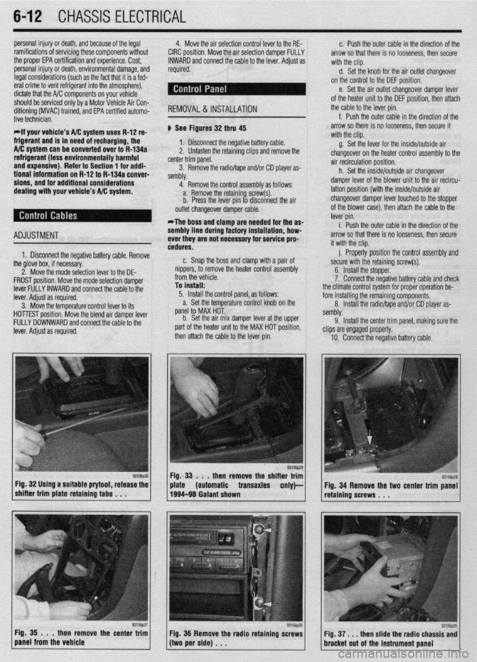
dealing with your vehicle’s A/C system. ti See Figures 32 thru 45
1. Disconnect the negative battery cable.
2, Unfasten the retaining clips and remove the
center trim panel.
3. Remove the radioltape and/or CD player as-
sembly,
4. Remove the control assembly as follows:
a. Remove the retaining screw(s).
b. Press the lever pin to disconnect the air
outlet changeover damper cable.
*The boss and clamp are needed for the as-
ADJUSTMENT
1. Disconnect the negative battery cable. Remove sembly line d
ever they are
dedures.
n Cnan i luring factory installation, how-
not necessary for service pro-
the glove box, if necessary,
2. Move the mode selection lever to the DE-
FROST position. Move the mode selection damper
lever FULLY INWARD and connect the cable to the
lever. Adiust as required.
3. M&e tht
3 temperature control lever to its
HOlli
5ST position. Move the blend air damper lever
FULL’t
’ DOWNWARD and connect the cable to the
lever. i
4djust as required. b,. dIIal, the boss and clamp with a pair of
nippers, to remove the heater control assembly
from the vehicle.
To install:
5. Install the control panel, as follows:
a. Set the temperature control knob on the
panel to MAX HOT..
b. Set the air mix damper lever at the upper
part of the heater unit to the MAX HOT position,
then attach the cable to the lever pin.
then remove the shi
Fig. 32 Using a suitable prytool, release the
automatic transaxles
93156p27 Fig. 35 . . .
then remove the center trim
panel from the vehicle
/(twiperside)... y Fig 36 Remove the radio retaining screws g. Set the lever for the inside/outside air
changeover on the heater control assemblv to the
air recirculation position.
h. Set the inside/outside air changeover
damper lever of the blower unit to the air recircu-
lation position (with the inside/outside air
changeover damper lever touched to the stopper
of the blower case), then attach the cable to the
lever pin.
i. Push the outer cable in the direction of the
arrow so that there is no looseness, then secure
it with the clip.
j. Properly position the control assembly and
secure with the retaining screw(s).
6. Install the stopper.
7. Connect the negative battery cable and check
the climate control system for proper operation be-
fore installing the remaining components.
8. Install the radio/tape and/or CD player as-
sembly.
9. Install the center trim oanel, makina sure the
clips are engaged properly. -
10. Connect the negative battery cable.
Fig. 34 Remove the two center trim panel
retaining screws . . .
Fig. 37, . . then slide the radio chassis and
bracket out of the instrument Dane1
Page 216 of 408
CHASSIS ELECTRICiL 6-13
.
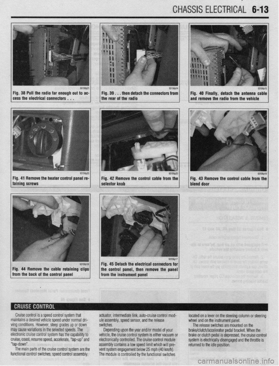
Fig. 38 Pull the radia far enough out to ac-
cess the electrical connectors . . . 9315fip14 Fig. 39. . . then detach the connectors from
I I Fig. 40 Finally, detach the antenna cable
the rear of the radio and remove the radio from the vehicle
Fig. 41 Remove the heater control panel re-
Fig. 42 Remove the control cable from the
g3156p1g / Fig 43 Remove the control cable from the
bleid door
Cruise control is a speed control system that
maintains a desired vehicle speed under normal dri-
ving conditions. However, steep grades up or down
may cause variations in the selected speeds. The !
electronic cruise control system has the capability to
cruise, coast, resume speed, accelerate, “tap-up” and
“tap-down”.
The main parts of the cruise control system are the
functional control switches, speed control assembly, actuator, intermediate link, auto-cruise control mod-
ule assembly, speed sensor, and the release
switches.
Depending upon the year and/or model of your
vehicle, the cruise control system is either vacuum or
electronically controlled. The cruise control module
assembly contains a low speed limit which will pre-
vent system engagement below 25 mph (40 km/h).
The module is controlled by the functional switches located on a lever on the steering column or steering
wheel and on the instrument panel.
The release switches are mounted on the
brake/clutch/accelerator pedal bracket. When the
brake or clutch pedal is depressed, the cruise control
system is electrically disengaged and the throttle is
returned to the idle position.
Page 217 of 408
6-14 CHASSIS ELECTRICAL
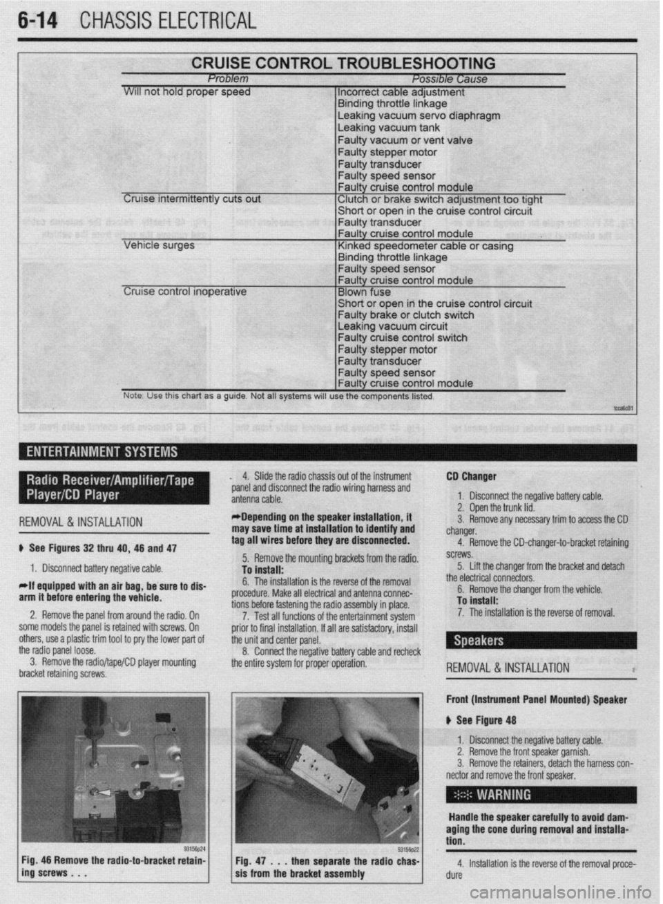
CRUISE CONTROL TROUBLESHOOTING Problem Posable Cause
WIII not hold proper speed 1 Incorrect cable adjustment
F.~. _I.~_ - 1L .-AL‘- I. I -
Cruise intermittently cuts out
trrnarng Inrome nnKage Leaking vacuum servo diaphragm
Leaking vacuum tank
Faulty vacuum or vent valve
Faulty stepper motor
Faulty transducer
Faulty speed sensor
Faulty cruise control module
‘ Clutch or brake switch adjustment too tight -chnrt *r nna* in the cruise control circuit
cer VI I”, . vt “y”‘,
I- Faulty transdu
Leaking vacuum circuit Faulty cruise control switch
Faulty stepper motor
Note. Use this chart as a guide. Not all systems will use the components listed.
t-,
I ,-- ,
REMOVAL&INSTALLATION
# See Figures 32 thru 40, 46 and 47
1. Disconnect battery negative cable.
*If equipped with an air bag, be sure to dis-
arm it before entering the vehicle.
2. Remove the panel from around the radio, On
some models the panel is retained with screws, On
others, use a plastic trim tool to pry the lower pad of
the radio panel loose.
3. Remove the radio/tape/CD player mounting
bracket retaining screws, 4. Slide the radio chassis out of the instrument
*panel and disconnect the radio wiring harness and
*Depending on the speaker installation, it
may save time at installation to identify and
tag all wires before they are disconnected.
5. Remove the mounting brackets from the radio.
To install:
6. The installation is the reverse of the removal
procedure. Make all electrical and antenna connec-
tions before fastening the radio assembly in place.
7. Test all functions of the entertainment system
prior to final installation. If all are satisfactory, install
the unit and center panel.
8. Connect the negative battery cable and recheck
the entire system for proper operation. CD Changer
1. Disconnect the negative battery cable.
2. Open the trunk lid.
3. Remove any necessary trim to access the CD
changer.
4. Remove the CD-changer-to-bracket retaining
screws.
5. Lift the changer from the bracket and detach
the electrical connectors.
6. Remove the changer from the vehicle.
To install:
7. The installation is the reverse of removal.
REMOVAL&INSTALLATION l
Front (Instrument Panel Mounted) Speaker
u See Figure 48
1. Disconnect the negative battery cable.
2. Remove the front speaker garnish.
3. Remove the retainers, detach the harness con-
nector and remove the front speaker,
Handle the speaker carefully to avoid dam-
aging the cone during removal and installa-
tion.
4. Installation is the reverse of the removal proce-
dure
Page 218 of 408
CHASSIS ELECTRlCiL 6-15
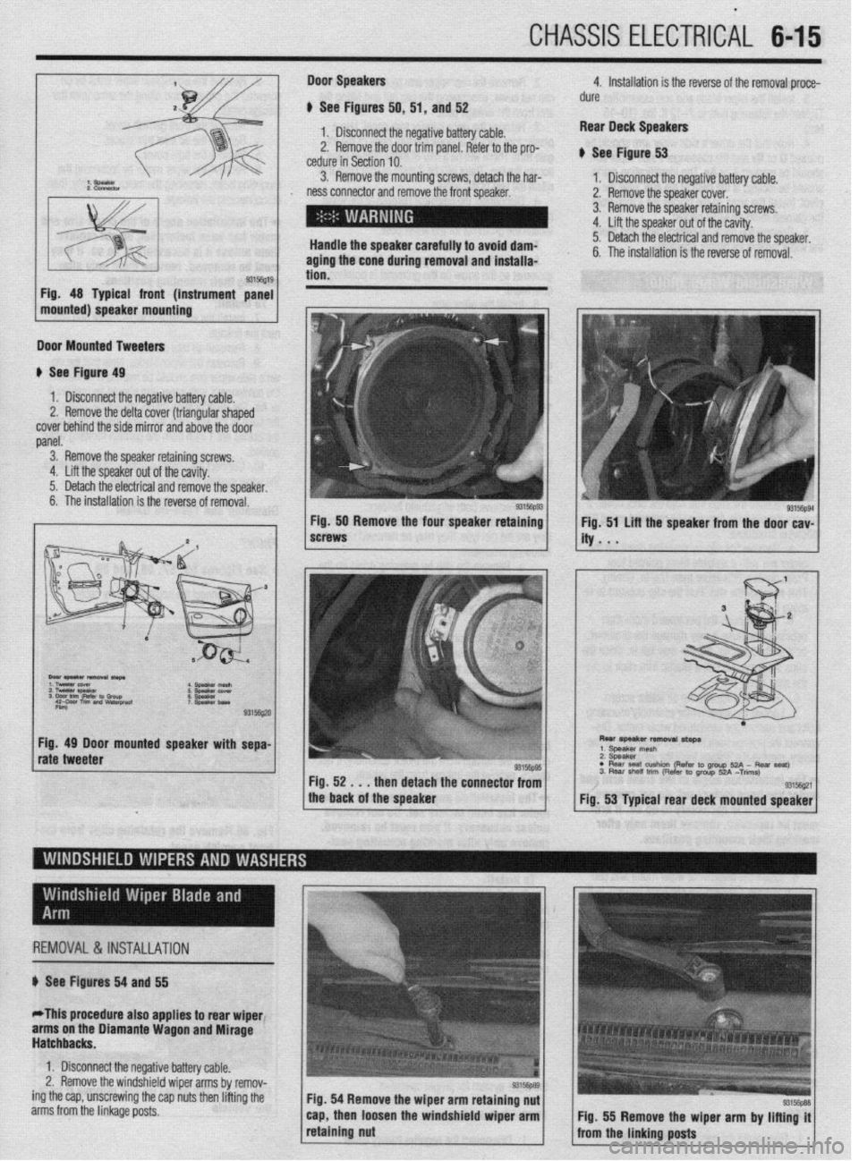
Door Speakers 4. Installation is the reverse of the removal proce-
) See Figures 50, 51, and 52 dure
-t
I. lJ13lr”IIIIObI IlIt: llaydwa n:n?.nnnnr, IL,^ ..^rr‘:.... battery &je, Rear Deck Speakers
2. Remove the door trim pa nel. Refer to the pro-
cedure in Section 10. # See Figure 53
3. Remove the mounting screws, detach the har-
1. Disconnect the negative battery cable.
ness connector and remove the front speaker. 2. Remove the speaker cover.
3. Remove the speaker retaining screws.
4. Lift the speaker out of the cavity.
Handle the speaker carefully to avoid dam- 5. Detach the electrical and remove the speaker,
aging the cone during removal and installa-
tion. 6. The installation is the reverse of removal.
93156g19
Fig. 48 Typical front (instrument panel
mounted) speaker mounting
Door Mounted Tweeters
# See Figure 49
1. Disconnect the negative battery cable.
2, Remove the delta cover (triangular shaped
cover behind the side mirror and above the door
panel.
3. Remove the speaker retaining screws
4. Lift the speaker out of the cavity.
5. Detach the electrical and remove the speaker,
6. The installation is the reverse of removal.
rate tweeter Fig. 50 Remove the four speaker retaining Fig. 51 Lifl the speaker from the door cav-
screws ity . . .
REMOVAL&lNSTAL~TlON
I
n See Figures 54 and 55
*This procedure also applies to rear wiper1
arms on the Diamante Wagon and Mirage
Hatchbacks.
1. Disconnect the negative battery cable.
2. Remove the windshield wiper arms by remov-
ing the cap, unscrewing the cap nuts then lifting the
arms from the linkage posts. Fig. 54 Remove the wiper arm retaining nut
cap, then loosen the windshield wiper arm
. . .._S~.. .
1 rerauung nut
I
9315W38 Fig. 55 Remove the wiper arm by lifting it
#--- at.- ,:-n-1-- ---‘- 1 mfifl me ffffnfffg pusfs
Page 219 of 408
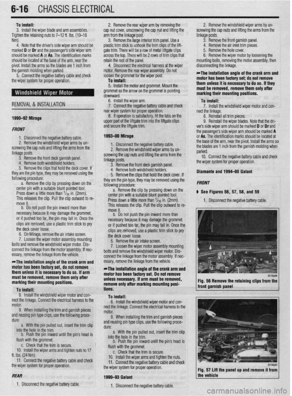
646 CHASSIS ELECTRICAL
To install: 2. Remove the rear wiper arm by removing the 2. Remove the windshield wiper arms by un-
3. Install the wiper blade and arm assemblies, cap nut cover, unscrewing the cap nut and lifting the screwing the cap nuts and lifting the arms from the
Tighten the retaining nuts to 7-12 ft. Ibs. (10-16 arm from the linkage post. linkage posts.
Nm). 3. Remove the large interior trim panel. Use a 3. Remove the front garnish panel.
4. Note that the drivers side wiper arm should be plastic trim stick to unhook the trim clips of the lift- 4. Remove the air inlet trim pieces.
marked D or Dr and the passenger’s side wiper arm gate trim. There will be a row of metal liftgate clips 5. Remove the hole cover.
should be marked A or As. The identification marks across the top. There will be 2 rows of trim clips that 6. Remove the wiper motor by loosening the
should be located at the base of the arm, near the retain the rest of the panel. mounting bolts, removing the motor assembly, then
pivot. Install the arms so the blades are 1 inch from 4. Disconnect the electrical harness at the wiper disconnecting the linkage.
the garnish molding when parked. motor. Remove the rear wiper assembly. Do not
5. Connect the negative battery cable and check loosen the grommet for the wiper post. *The installation angle of the crank arm and
the wiper system for proper operation. To install: motor has been factory set; do not remove
5. Install the motor and grommet. Mount the them unless it is necessary to do so. If they
grommet so the arrow on the grommet is pointing must be removed, remove them only after
downward. marking their mounting positions.
REMOVAL&INSTALLATION 6. Install the wiper arm. To install:
7. Connect the negative battery cable and check 7. Install the windshield wiper motor and con-
rear wiper system for proper operation. nect the linkage.
1999-92 Mirage 8. If operation is satisfactory, fit the tabs on the 8. Reinstall all trim pieces.
upper part of the liftgate trim into the liftgate clips 9. Reinstall the wiper blades. Note that the dri-
FRONT ‘~ and secure the liftgate trim. ver’s side wiper arm should be marked D or Dr and
the passengers side wiper arm should be marked A
1. Disconnect the negative battery cable. 1993-00 Mirage or As. The identification marks should be located at
2. Remove the windshield wiper arms by un-
1. Disconnect the negative battery cable. the base of the arm, near the pivot. Install the arms so
screwing the cap nuts and lifting the arms from the
linkage posts. 2. Remove the windshield wiper arms by un- the blades are 1 inch from the garnish molding when
screwing the cap nuts and lifting the arms from the . parked.
3. Remove the front deck garnish panel.
linkage posts, 10. Connect the negative battery cable and check
4. Remove both windshield holders.
3. Remove the front deck garnish panel. the wiper system for proper operation.
5: Remove the clips that hold the deck cover. If
they are the pin type, they may be removed using the 4. Remove both windshield holders.
5. Remove the clips that hold the deck cover. If Diamante and 199440 Galant
following procedure:
a. Remove the clip by pressing down on the they are the pin type, they may be removed using the
, following procedure. FRONT
center pin with a suitable blunt pointed tool.
Press down a little more than l/r6 in. (2mm). a. Remove the clip by pressing down on the
b See Figures 56, 57, 58, and 59
This releases the clip. Pull the clip outward to re- center pin with a suitable blunt pointed tool.
move it. Press down a little more than l/r6 in. (2mm). 1. Disconnect the negative battery cable.
b. Do not push the pin inward more than This releases the clip. Pull the clip outward to re-
necessary because it may damage the grommet, move it.
or if pushed too far, the pin may fall in. Once the b. Do not push the pin inward more than
clips are removed, use a plastic trim stick to pry necessary because it may damage the grommet
the deck cover loose. or if pushed too far, the pin may fall in. Once the
6. On Mirage, remove the air intake screen. clips are removed, use a plastic trim stick to pry
7, Loosen the wiper motor assembly mounting the deck cover loose.
boltsand remove the windshield wiper motor. Dis- 6. Remove the air intake screen.
connect the linkage from the motor assembly. If nec- 7. Loosen the wiper motor assembly mounting
essary, remove the linkage from the vehicle. bolts and remove the windshield wiper motor. Dis-
connect the linkaae from the motor assemblv. If nec-
*The installation angle of the crank arm and
motor has been factory set, do not remove
them unless it is necessary to do so. If arm
must be removed, remove them only after
marking their mounting positions.
To Install:
8. Install the windshield wiper motor and con-
nect the linkage. Connect the electrical harness to the
motor.
9. When installing the trim and garnish pieces
and reusing pin type clips, use the following proce-
dure:
a. With the pin pulled out, insert the trim clip
into the hole in the trim.
b. Push the pin inward until the pin’s head is
flush with the grommet.
c. Check that the trim is secure.
IO. Install the wiper arms and tighten nuts to 17
ft. Ibs. (24 Nm).
11. Connect the negative battery cable and check
the wiper
systerr I-- -_-^-_ -----,:-- II 101 plupel uperatlull.
essary, remove the linkage from the vehicle.-
*The installation angle of the crank arm and
motor has been factory set. Do not remove
unless necessary. If arm must be removed,
remove only after marking mounting posi-
tions.
To install:
8. Install the windshield wiper motor and con-
nect the linkage. Connect the electrical harness to the
motor.
9. When installing the trim and garnish pieces
and reusing pin type clips, use the following proce-
dure:
a. With the pin pulled out, insert the trim clip
into the hole in the trim.
b. Push the pin inward until the pin’s head is
flush with the grommet.
c. Check that the trim is secure.
10. Install the wiper arms and tighten the nuts.
11. Connect the negative battery cable and check
the wiper system for proper operation. Fig. 56 Remove the retaining clips from the
front garnish panel
REAR
1990-93 Galant
1. Disconnect the negative battery cable.
1. Disconnect the negative battery cable.
Fig. 57 lift the panel up and remove it from 1
the vehicle
I
Page 220 of 408
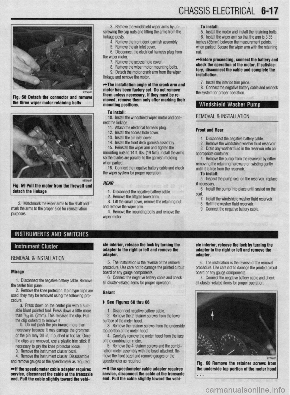
CHASSIS ELECTRICAL 647
3. Remove the windshield wiper arms by un-
screwing the cap nuts and lifting the arms from the
linkage posts.
4. Remove the front deck garnish assembly.
Iver.
xl harness plug from
,I6 #-n\,LIr 5. Remove the air inlet c(
6. Disconnect the electric
the wiper motor.
7. Remove the access ho,, LIVIGil. To install:
5. Install the motor and install the retaining bolts.
6. Install the wiper arm so that the arm is 3.35
inches (85mm) between the measurement points,
when parked. Secure the wiper arm with the retaining
nut.
*Before proceeding, connect the battery and
8. Remove the wiper motor mounting bolts.
9. Detach the motor crank arm from the wiper
linkane and remnve the mntnr
motor has been factory set. Do not remove
them unless necessary. if they must be re-
moved, remove them only after marking their
mounting positions. check the operation of the motor. if satisfae-
tory, disconnect the cable and complete the
installation.
o. WIIIIW LIE Il~&WVt: vatreryoable and recheck
the system for proper operation.
..-
a- - ‘- _ _ _ . _ _ _
*The installation angle of the crank arm and 7. Install the interior trim piece
n II ^_^^^ IAL- -^I-I:..- L-AL--
To install:
10. Install the windshield wiper motor and con-
REMOVAL&INSTALLATION nect the linkage.
I 14. Install the front deck garnish assembly. I. YIV”“I1IIYVL VI” “UyuL’.” “UL’“‘, UUUIU. 2. Remove the windshield washer fluid resarvnir
’ 11. Attach the electrical harness plug.
12. Install the access hole cover.
13. Install the air inlet cover.
15. Reinstall the wiper arm and tighten the
mounting nuts to 14 ft. Ibs. (19 Nm). Install the arms
so the blades are parallel to the garnish molding -
Front and Rear
1 nivnnnprt the nonatiua haltorv rahlo
3. Drain any washer fluid in the reservoir into an
appropriate container.
4.
I when parked. Remove the pump from the reservoir by either
16. Connect the neaative batterv cable and check removing the retaining hardware or twisting gently
tlntil it is frpp frnm thP rosorvnir the wiper system for proper operation.
lo Install:
5. Inspect the pump seal on the reservoir, replace
/ de&h the linkage Fig 59 Pull the motor from the firewaii and
“‘%‘y 1 ““I”“,,,,,, the if necessary.
1 1 Disconn& thP rwnativo hatton/ rahlm 6. Install the pump into place until seated on the .I,” ~‘“p.L’,” YULL”‘, -YI”. liftgate lower trim. seal.
3: Lift the smatr CUVBI, I~IIIUV~ tilt: lfAdllllll~ IIUL II --. .-- -^- ^..^ .L^ -_,_:..:-- -.A 7. Install the windshield washer fluid reservoir. 2. Matchmark the wirier arms tn the shaft and A Refill thp wxhpr fllk-l rpqprvnir markthe arms to the proper side for reinstallation and remove the wiper arm.
4. Remove the mountina bolts and remove the “. .,“...S .V.” ....“III. ,*..*” IYUY..“m,.
9. Connect the negative battery cable.
REMOVAL&INSTALLATION
tie interior, release the lock by turning the tie interior, release the lock by turning the
adapter to the right or left and remove the adapter to the rigM or left and remove the
adapter. adapter.
5. The installation is the reverse of the removal
6. The installation is the reverse of the removal
Mirage
1. Disconnect the negative battery cable. Remove
the center trim panel. procedure. Use care not to damage the printed circuit procedure. Use care not to damage the printed circuit
board or any gauge components.
board or any gauge components.
6. Connect the negative battery cable and check
7. Connect the negative battery cable and check
all cluster-related items for proper operation. i III cluster-related items for proper operation.
2. Remove the knee protector. If pin type clips are
used, they may be removed using the following pro-
cedure:
a. Press down on the center pin with a suit-
able blunt pointed tool. Press down a little more
than ‘IIS in. (2mm). This releases the clip. Pull
the clip outward to remove it.
b. Do not push the pin inward more than
necessary because it may damage the grommet
or the pin may fall in, if pushed in too far. Once
the clips are removed, use a plastic trim stick if
necessary to pry the knee protector loose.
3. Remove the instrument cluster bezel.
4. Remove the instrument cluster. Disassemble
and remove gauges or the speedometer as required.
*if the speedometer cable adapter requires
setvice, disconnect the cable at the transaxie
end. Pull the cable slightly toward the vehi- Gaiant
@ See Figures Bg thru 66
1. Disconnect negative battery cable.
2. Remove the 2 retainer screws from the lower
surface of the meter hood.
3. Remove the retainer screws from the underside
top portion of the meter hood.
4. Carefully remove the meter hood from the face
of the combination meter.
5. Remove the 4 retainer screws and the combi-
nation meter assembly with the bezel attached. Re-
move the front bezel and remove gauges or the
speedometer as required.
*if the speedometer cable adapter requires
service, disconnect the cable at the transaxie
end. Pull the cable slightly toward the vehi-