MITSUBISHI DIAMANTE 1900 Repair Manual
Manufacturer: MITSUBISHI, Model Year: 1900, Model line: DIAMANTE, Model: MITSUBISHI DIAMANTE 1900Pages: 408, PDF Size: 71.03 MB
Page 181 of 408
.
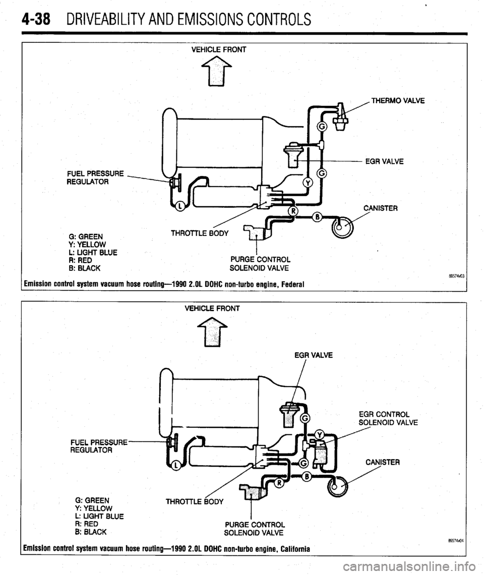
4-38 DRIVEABILITYAND EMISSIONS CONTROLS
FUEL PRESSURE
REGULATOR
0: GREEN
y: YELLOW
L: LIGHT BLUE
R: RED
B: BLACK VEHICLE FRONT
PURGE ‘CONTROL
SOLENOID VALVE .VE
imission control system vacuum hose routing-1990 2.OL DOHC non-turbo engine, Federal
VEHICLE FRONT
EGF VALVE
EGR CONTROL
SOLENOID VALVE
FUEL PRESSURE
REGULATOR
STER
G: GREEN
y: YELLOW
L: UGHT BLUE
I
R: RED
PURGE CONTROL
B: BLACK
SOLENOID VALVE 89574vo4 imission control system vacuum hose routing-1990 2.OL DOHC non-turbo engine, California
Page 182 of 408
.
DRIVEABILITYAND EMISSIONS CONTROLS 4-39
VEHICLE FRONT
FI
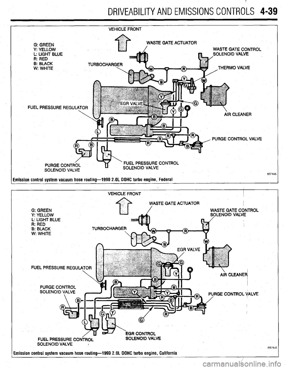
Emission control system vacuum hose routing-1990 2.OL DOHC turbo engine, Federal
VEHICLE FRONT I
STE GATE ACTUATOR
G: GREEN
y: YELLOW LENOID VALVE
L: LIGHT BLUE
R: RED
B: BLACK TURBOCHARGE
w: WHITE
FUEL PRESSURE REGU
RGE CONTROL VALVE
FUEL PRESSURE CO OLENOID VALVE
SOLENOID VALVE I
Emission control system vacuum hose routing-1990 2.OL DOHC turbo engine, California
89574VO6
Page 183 of 408
4-40 DRIVEABILITYAND EMISSIONS CONTROLS
EVAPORATIVE EMISSION PURGE SOLENOID
I
EVAPORATIVE
CANISTER THROlTLE BODY
THERMAL VACUUM VALVE $d yEAt FUEL PRESSURE
- REGULATOR
G: GREEN
y: YELLOW
L: LIGHT BLUE
R: RED VEHICLE FRONT
8: BLACK
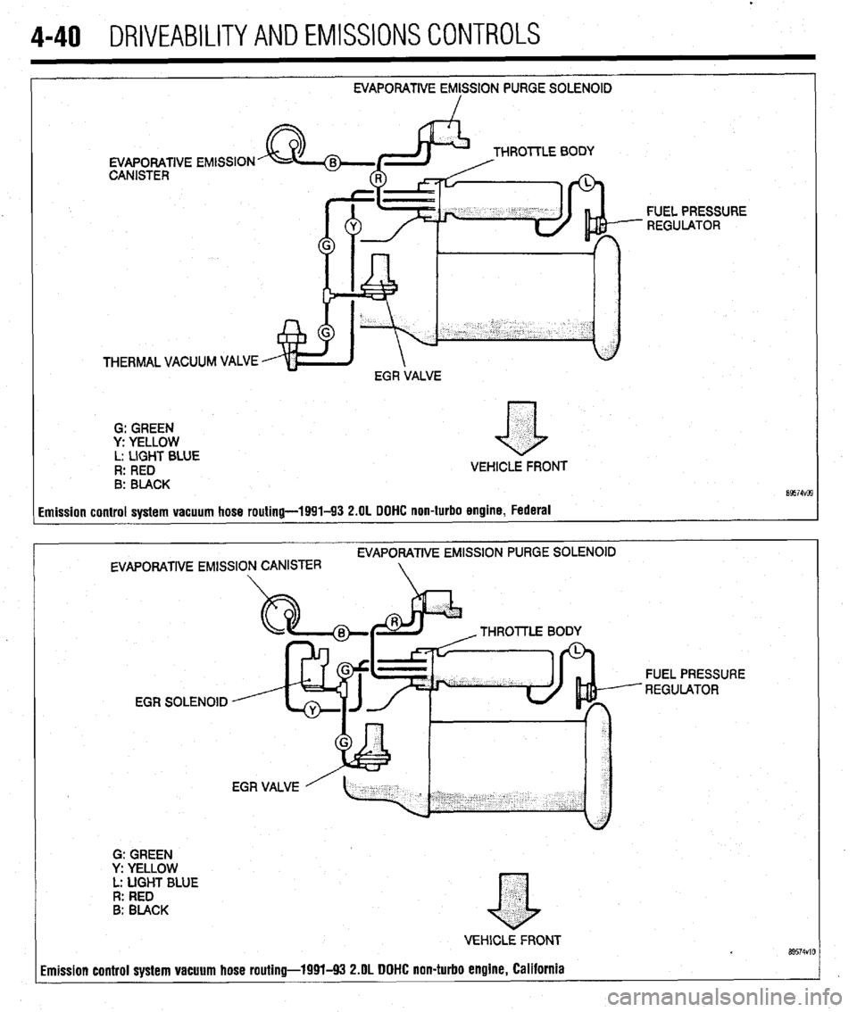
imission control system vacuum hose routing-1991-93 2.OL DOHC non-turbo engine, Federal
EVAPORATIVE EMlSSlON PURGE SOLENOID
EVAPORATIVE EMISSION CANISTER
G: GREEN
Y: YELLOW
L: UGHT BLUE
R: RED
B: BLACK THROllLE 80
EGR SOLENOID FUEL PRESSURE
REGULATOR
.
a
VEHlCLE FRONT Bs574VlO imission control system vacuum hose routing-1991-93 2.OL DOHC non-turbo engine, California
Page 184 of 408
.
DRIVEABILITYAND EMISSIONS CONTROLS 4-41
EVAPORATIVE EMISSION PURGE
FUEL PRESSURE SOLENOID
THERMAL FUEL PRESSURE REGULATOR
AlRC
VACUUM VALVE
TURBOCHARGER
G: GREEN
y: YELLOW
L: UGHT BLUE
R: RED
B: BLACK
w: WHlTE
TURBOCHARGER WASTE P
TURBOCHARGER WASTE
GATE SOLENOID
GATE ACTUATOR
a
VEHlCLi FRONT
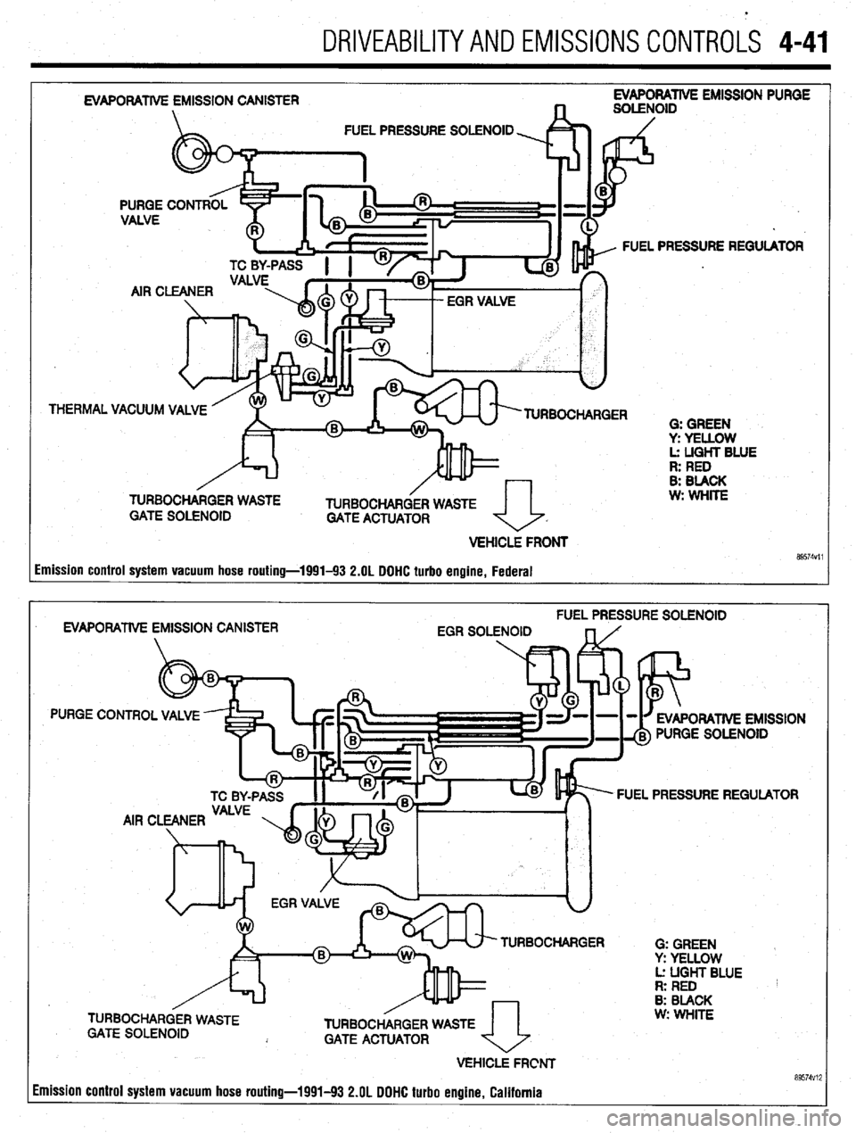
89574Vll Imission control system vacuum hose routing-1991-93 2.OL DDHC turbo engine, Federal
FUEL PRESSURE SOLENOID
EVAPORATlVE EMISSION CANISTER
EGR SOLENOID
PURGE CONTROL VALVE
ORATlVE EMISSION
PURGE SOLENOID
FUEL PRESSURE REGULATOR
TURBOCHARGER
0: GREEN
Y: YELLOW
Lz UGHT BLUE
R: RED
8: BLACK
TURBOCHARGER WASTE
GATE ACTUATOR
VEHICLE FRCNT
Imission control system vacuum hose routing-1991-93 2.OL DOHC turbo engine. California w: WHITE
a9574vi;
Page 185 of 408
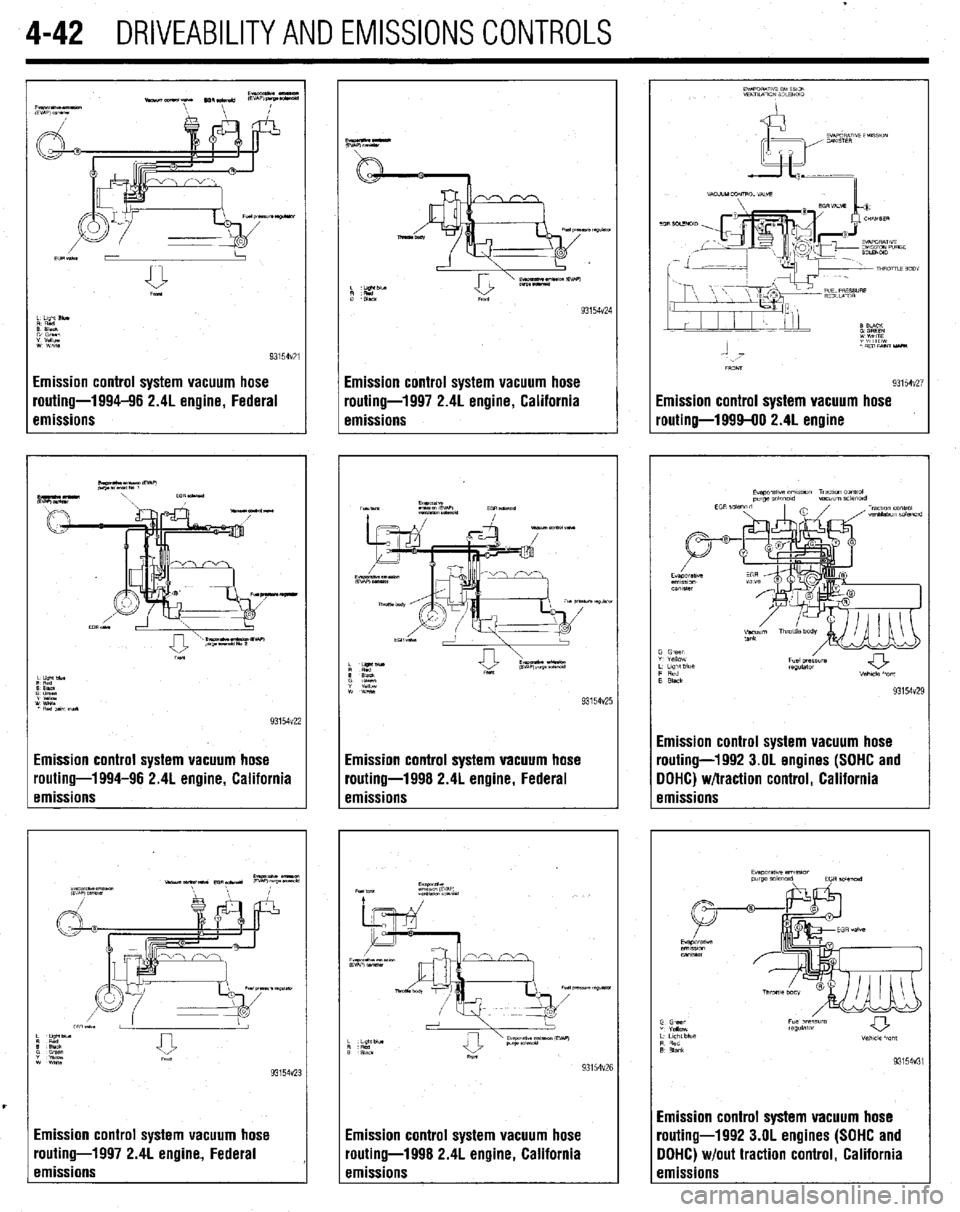
4-42 DRIVEABILITYAND EMISSIONS CONTROLS
Emission control system vacuum hose
routing-1994-96 2.4L engine, Federal
emissions
Emission control system vacuum hose
routing-1994-96 2.4L engine, California
emissions
Emission control system vacuum hose
routing-1997 2.4L engine, Federal
emissions I Emission control system vacuum hose I routing-1997 2.4L engine, California I emissions
TV TbE
93154v25
I Emission control system vacuum hose I routing-1998 2.4L engine, Federal I emissions
93154v26
El
ro
el nission control system vacuum hose
uting-1998 2.4L engine, California
nissions
93154v24
Emission control system vacuum hose
routing-1999-00 2.4L engine
93154~26
Emission control system vacuum hose
routing-1992 3.OL engines (SOHC and
DDHC) w/traction control, California
emissions
93154v31
Imission control system vacuum hose
-outing-l992 3.OL engines (SOHC and
IOHC) w/out traction control, California
:missions
Page 186 of 408
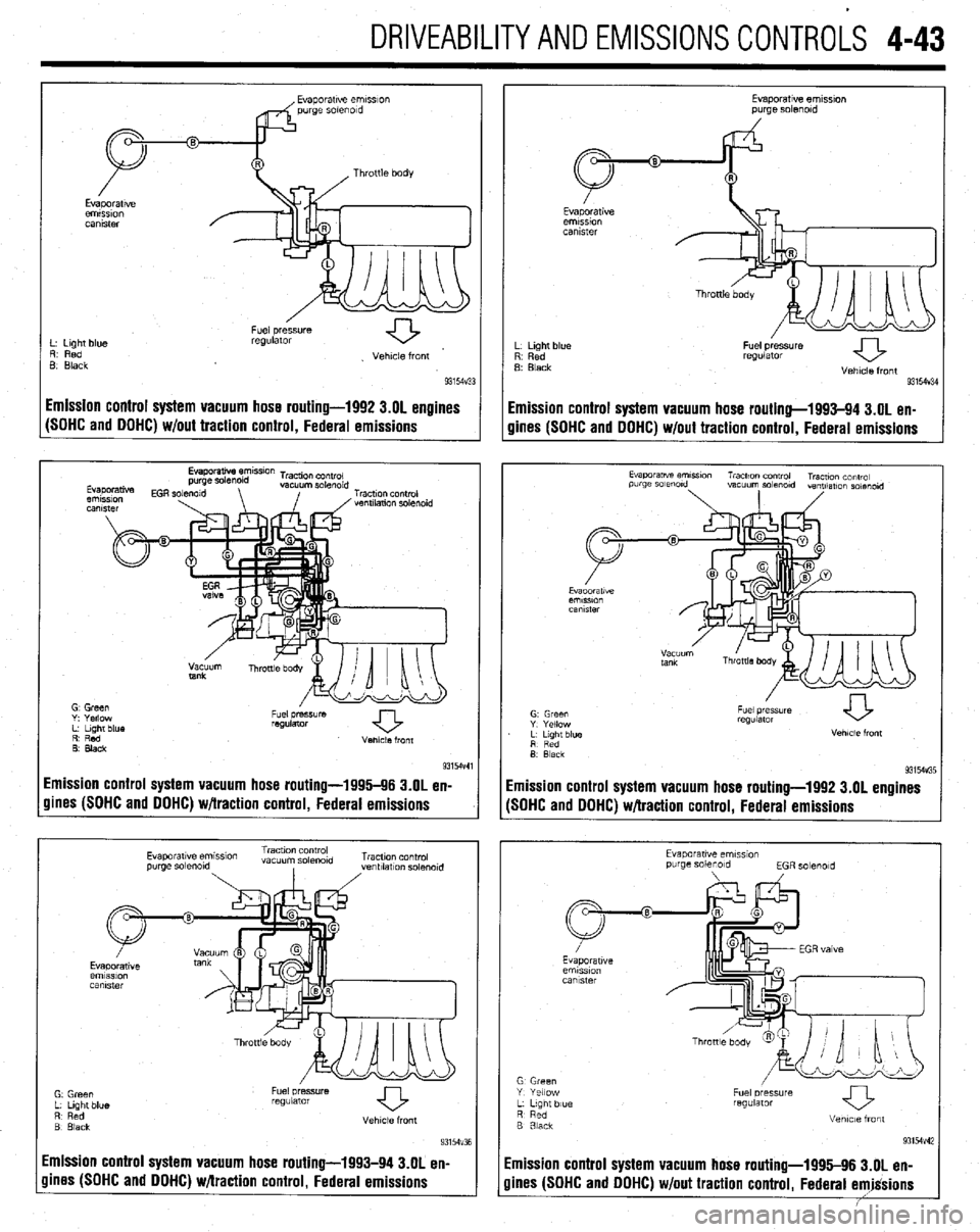
DRIVEABILITYAND EMISSIONSCONTROL-S 4-43
L. Light blue
R. Red
B Black Fuel pressure
regulator
. Vehicle front
93154~33
I Fuel pressure
regulator
Vehicle front
93154V34
Emission control system vacuum hose routing-1992 3.01 engines
Emission control system vacuum hose routing-1993-94 3.OL en-
(SOHC and OOHC) w/out traction control, Federal emissions
gines (SOHC and DOHC) w/out traction control, Federal emissions
R’ Red
0. Black Venlcle front
9315-M
Emission control system vacuum hose routing-1996-96 3.OL en-
gines (SOHC and DOHC) w/traction control, Federal emissions
Evaporatwe em~smn Traction control
vacuum so&old Tracuon control
purge solmold
, ,ventllatlon solmold
Emission control system vacuum hose routing-1993-94 3.OL en-
Evaporatwe ernmon
purge solenoid
L Light blue
R Red
B Black
Fuel pressure
regulator
Vehicle front
931W3E
imission control system vacuum hose routing-1992 3.OL engines
SOHC and DOHC) w/traction control, Federal emissions
Evaporawe emss~on
purge solenoid
EGR solmold
G Green
Y Yellow
L L,gnt blue
R Red
B 3lack Fuel oressure
regUlatOr
Vetme front
93154v42
imission control system vacuum hose routing-1995-96 3.OL en-
lines (SOHC and DOHC) w/out traction control, Federal emjgsions
Page 187 of 408
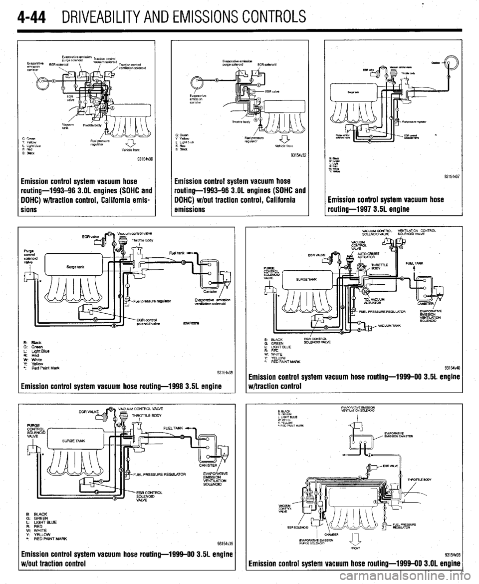
4-44 DRIVEABILITYAND EMISSIONS CONTROLS
Emission control system vacuum hose
pouting-1993-96 3.OL engines (SOHC and
DOHC) w/traction control, California emis-
rions Emission control system vacuum hose
routing-1993-96 3.OL engines (SOHC and
DOHC) w/out traction control, California
emissions
Emission control system vacuum hose routing-1998 3.5L engine
Emission control system vacuum hose routing-199%00 3.5L engine
w/out traction control Emission control system vacuum hose
routing-1997 3.5L engine
Emission control system vacuum hose routing-1999-00 3.5L engim
Mtraction control
Emission control system vacuum hose routing-199940 3.OL engine
Page 188 of 408
BASIC FUEL SYSTEM DIAGNOSIS 5-2
FUEL LINES AND FllllNGS 5-2
FUEL LINE FITTINGS 5-2
REMOVAL &INSTALLATION 5-2
MULTI-POINT FUEL INJECTION
SYSTEM (MPI) 5-3
GENERALINFORMATION 5-3
FUELSYSTEM SERVICE
PRECAUTIONS 5-3
RELIEVING FUELSYSTEM
PRESSURE 5-3
THROTTLEBODY 5-3
REMOVAL & INSTALLATION 5-3
FUEL RAIL AND INJECTORS(S) 5-4
REMOVAL &INSTALLATION 5-4
TESTING 5-8
FUELPRESSUREREGULATOR 5-9
REMOVAL & INSTALLATION 5-9
PRESSURERELIEFVALVE 5-9
REMOVAL&INSTALLATION 5-9
FUEL TANK 5-10
TANKASSEMBLY 5-10
REMOVAL&INSTALLATION 5-10
Page 189 of 408
I
5-2, FUELSYSTEM
When there is a problem starting or driving a vehi-
“is there fuel? will often lead to solving most basic
cle, two of the most important checks involve the ig- problems. For ignition system diagnosis and testing,
nition and the fuel systems. The questions most me-
please refer to the information on engine electrical
chanics attempt to answer first, “is there spark?” and
components and ignition systems found earlier in this manual. If the ignition system checks out (there
is spark), then you must determine if the fuel system
is operating properly (is there fuel?).
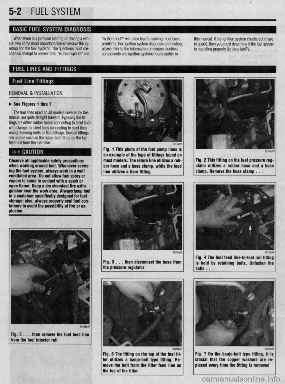
REMOVAL&INSTALLATION
# See Figures 1 thru 7
The fuel lines used on all models covered by this
manual are quite straight forward. Typically the fit-
tings are either rubber hoses connecting to steel lines
with clamps, or steel lines connecting to steel lines
using retaining bolts or flare fittings. Several fittings
are unique such as the banjo-bolt fitting on the fuel
feed line from the fuel filter.
ventitateu area. Do not allow fuel spray or
vapors to come in contact with a spark or
ooen flame. Keen a drv chemical fire extin- Observe all applicable safety precautions
when working around fuel. Whenever servic-
ing the fuel system, always work in a well
___ _ . . . _
guisher near the’work &ea. Always keep fuel
in a container specifically designed for fuel
storage; also, always pmperly seal fuel con-
tainers to avoid the possibility of fire or ex-
plosion. Fig. 1 This photo of the fuel pump lines is
an example of the type of fittings found on
most models. The return line utilizes a rub-
ber hose and a hose clamp, while the feed
line utilizes a flare fitting
ren disconnect the hose from
1 the pressure regulator Fig. 2 This fitting on the fuel pressure reg-
ulator utilizes a rubber hose and a hose
clamp. Remove the hose clamp . . .
93153p45 Fig. 4 The fuel feed line-to-fuel rail fitting
is held by retaining bolts. Unfasten the
bolts . . .
Fig. 5 . . .
then remove the fuel feed line
from the fuel injector rail
I
1 Fig. 6 The fitting on the too of the fueg;?lz
I I
93155pzl Fig. 7 On the banjo-bolt type fitting, it is
ter utilizes a banjo-bolt type fitting. Re-
I I crucial that the copper washers are re-
move the bolt from the filter feed line on placed every time the fitting is removed
the top of the filter
Page 190 of 408
FUELSYSTEM 513
l Always replace worn fuel fitting O-rings with
new. Do not substitute fuel hose or equivalent, where
I
The Multi-Point Injection (MPI) system is electroni-
rally controlled by the Engine Control Module (ECM),
based on data from various sensors. The ECM controls
the fuel flow, idle speed and ignition timing. fuel pipe is installed.
Fuel is supplied to the injectors by an electric in-
tank fuel pump and is distributed to the respective in-
jectors via the main fuel pipe. The fuel pressure ap-
plied to the injector is constant and higher than the
pressure in the intake manifold. The pressure is con-
trolled by the fuel pressure regulator. The excess fuel
is returned to the fuel tank through the fuel return pipe.
When an electric current flows in the injector, the
injector valve is fully opened to supply fuel. Since the
fuel pressure is constant, the amount of the fuel in-
jetted from the injector into the manifold is increased
or decreased in proportion to the time the electric
current flows. Based on ECU signals, the injectors in-
ject fuel to the cylinder manifold ports in firing order. Fuel injection systems remain under pres-
sure after the engine has been turned OFF.
Properly relieve fuel pressure before discon-
neeting any fuel lines. Failure to do so may
result in fire or personal injury.
1. Turn the ignition to the OFF position.
2. Loosen the fuel filler cap to release fuel tank
pressure.
I
The flow rate of the air drawn through the air
cleaner is measured by the air flow sensor. The air
enters the air intake plenum or manifold through the
throttle body. In the intake manifold, the air is mixed
with the fuel from the injectors and is drawn into the
cylinder, The air flow rate is controlled according to
the degree of the throttle valve and the servo motor
openings. The system is monitored through a num-
ber of sensors which feed information on engine con-
ditions and requirements to the ECM. The ECM cal-
culates the injection time and rate according to the
signals from the sensors,
Safety is the most important factor when perform-
ing not only fuel system maintenance but any type of
maintenance. Failure to conduct maintenance and re-
pairs in a safe manner may result in serious personal
injury or death. Maintenance and testing of the vehi-
cle’s fuel system components can be accomplished
safely and effectively by adhering to the following
rules and guidelines.
l To avoid the possibility of fire and personal in-
jury, always disconnect the negative battery cable un-
less the repair or test procedure requires that battery
voltage be applied.
l Always relieve the fuel system pressure prior to
disconnecting any fuel system component (injector,
fuel rail, pressure regulator, etc.), fitting or fuel line
connection. Exercise extreme caution whenever re- Observe all applicable safety precautions
when working around fuel. Whenever servic-
ing the fuel system, always work in a well
ventilated area. Do not allow fuel spray or va-
pors to come in contact with a spark or open
flame. Keep a dry chemical fire extinguisher
near the work area. Always keep fuel in a con-
tainer specifically designed for fuel storage;
also, always properly seal fuel containers to
avoid the possibility of fire or explosion.
3. For the Mirage, Diamante, and 1994-00
Galant, remove the rear seat cushion, then remove
the service cover and detach the fuel pump harness
connector.
4. For the 1990-93 FWD Galant, detach the fuel
pump harness connector located in the area of the
fuel tank. It may be necessary to raise the vehicle to
access the connector.
5. For the 1990-93 AWD Galant, remove the car-
pet from the trunk, locate the fuel tank wiring at the
pump access cover, then detach the wiring.
6. Start the vehicle and allow it to run until it
stalls from lack of fuel. Turn the key to the OFF posi-
tion.
7. Disconnect the negative battery cable, then at-
tach the fuel pump connector. Install the access .
cover, cushion or carpet as necessary.
8. Wrap shop towels around the fitting that is be-
ing disconnected to absorb residual fuel in the lines.
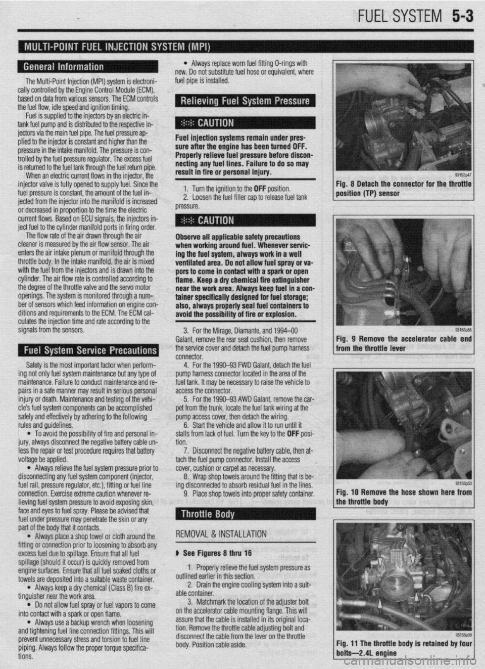
9. Place shop towels into proper safety container. Fig, 8 Detach the connector for the throttle
position (TP) sensor
93153ps5 Fig, 9 Remove the accelerator cable end
from the throttle lever
Fig. IO Remove the hose shown here from
lieving fuel system pressure to avoid exposing skin,
face and eyes to fuel spray. Please be advised that
fuel under pressure may penetrate the skin or any
part of the body that it contacts.
l Always place a shop towel or cloth around the
fitting or connection prior to loosening to absorb any
excess fuel due to spillage. Ensure that all fuel
spillage (should it occur) is quickly removed from
enginesurfaces. Ensure that all fuel soaked cloths or
towels are deposited into a suitable waste container.
l Always keep a dry chemical (Class B) fire ex-
tinguisher near the work area.
l Do not allow fuel spray or fuel vapors to come
into contact with a spark or open flame.
l Always use a backup wrench when loosening’
and tightening fuel line connection fittings. This will
prevent unnecessary stress and torsion to fuel line
piping. Always follow the proper torque specifica-
tions. REMOVAL &INSTALLATION
p See Figures 8 thru 18
1. Properly relieve the fuel system pressure as
outlined earlier in this section.
2. Drain the engine cooling system into a suit-
able container.
3. Matchmark the jocation of the adjuster bolt
on the accelerator cable mounting flange. This will
assure that the cable is installed in its original loca-
tion. Remove the throttle cable adjusting bolt and
disconnect the cable from the lever on the throttle
body. Position cable aside.