MITSUBISHI DIAMANTE 1900 Repair Manual
Manufacturer: MITSUBISHI, Model Year: 1900, Model line: DIAMANTE, Model: MITSUBISHI DIAMANTE 1900Pages: 408, PDF Size: 71.03 MB
Page 161 of 408
.
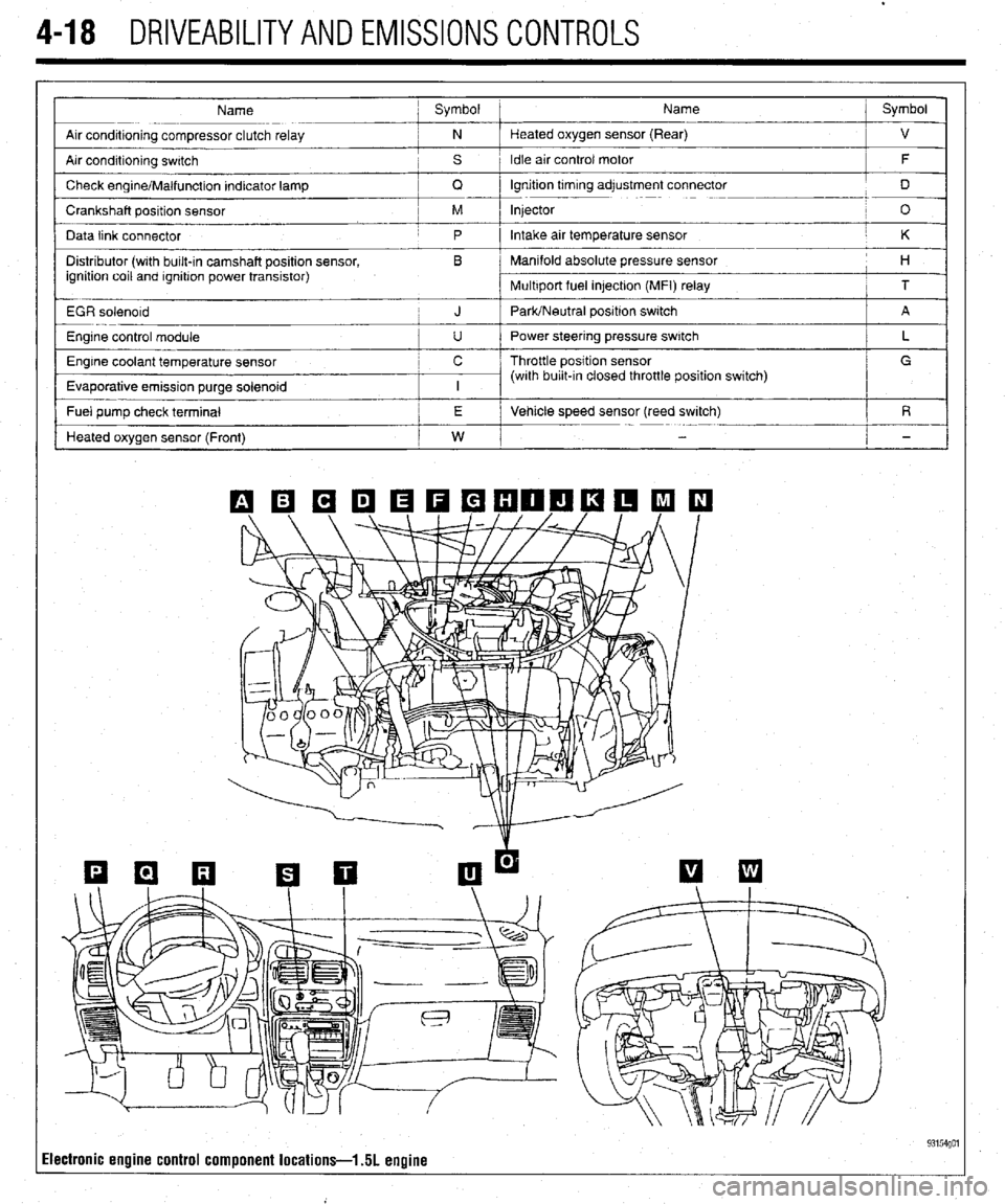
4-18 DRIVEABILITYAND EMISSIONS CONTROLS
Name ; Symbol Name j Symbol
I
Arr conditioning compressor clutch relay ; N Heated oxygen sensor (Rear)
j ”
Air condrtioning swatch , s 1 Idle air control motor
/ F
/
Check engrne/Malfunction Indicator lamp
/ Q lgnrtion trmrng adjustment connector
j D
Crankshaft position sensor / M Injector
! O
Data link connector
j p Intake air temperature sensor / K
Distributor (wrth bulk-in camshaft position sensor, , B Manifold absolute pressure sensor
ignition coil and rgnrtron power transistor) I 1 H
Multrport fuel in]ectron (MFI) relay
i T
EGR solenord
i J PaWNeutral positron switch j A
Engine control module
I u I Power steering pressure switch
Engine coolant temperature sensor c / Throttle position sensor
Evaporative emission purge solenoid
I I I (with burl&In closed throttle position switch) / L _
/ G
I
I
- Fuel pump check terminal /
I j E i Vehicle speed sensor (reed switch)
/ R
Heated oxygen sensor (Front)
I w I
i -
Ilectronic engine control component locations-l 51 engine 93154go1
Page 162 of 408
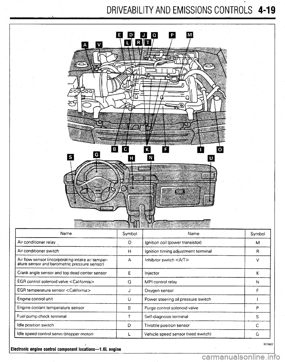
DRIVEABILITYAND EMISSIONS CONTROLS 4-19
Name
Air conditroner relay
Air condrtroner switch
Air flow sensor (rncorporatrng Intake arr temper-
ature sensor and barometric pressure sensor) Symbol Name
Symbol
0 ignition cot1 (power transrstor)
M
H lgnrtion trmtng adjustment terminal
R
A Inhibitor switch
V
Crank angle sensor and top dead center sensor
E Injector K
1 EGR control solenord valve
1 Q 1 MPI control relay
1 N 1
EGR temperature sensor
Engine control unit
Engine coolant temperature sensor
I Fuel pump check terminal J Oxygen sensor F
U Power steering 011 pressure switch I
0 Purge control solenord valve
P
1 T I Self-dragnosis terminal
I s I
I idle posrtron swatch
1 D 1 Throttle positron sensor I c I
Idle speed control servo (stepper motor)
L Vehicle speed sensor (reed swatch)
G
ilectronic engine control component lochions- .6L enuine 93154go;
Page 163 of 408
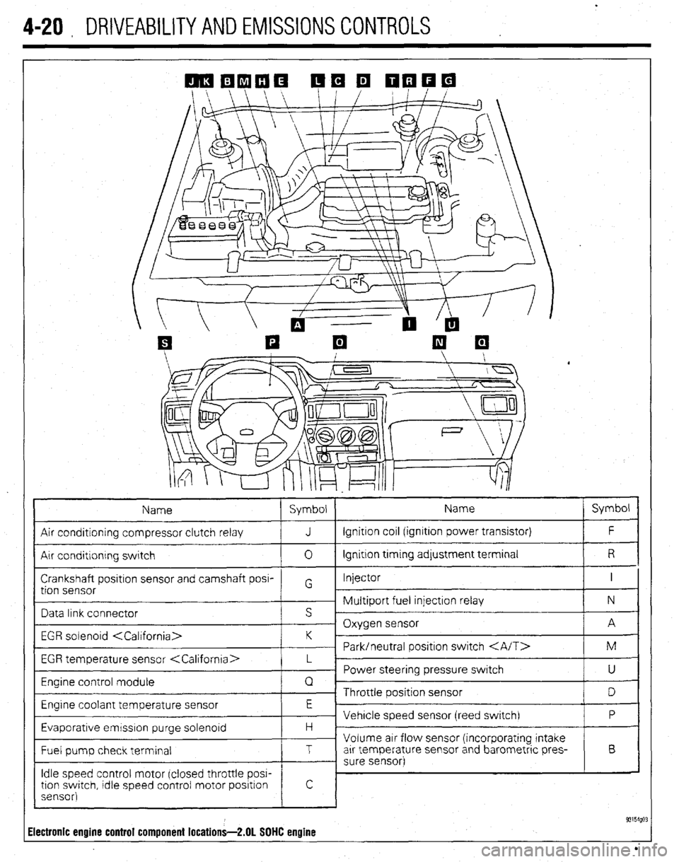
4-20 , DRIVEABILITYAND EMISSIONS CONTROLS
Name Symbol Name Symbol
Air conditioning compressor clutch relay J Ignition coil (ignition power transistor) F
Air conditlonrng switch 0 Ignition trming adjustment terminal R
Crankshaft positron sensor and camshaft posi- Injector I
tion sensor G
~ Multiport fuel injection relay N
Data link connector s ’
- Oxygen sensor A
EGR solenoid
~ Park/neutral positron switch M
EGR temperature sensor
_ Power steering pressure switch
U
Engine control module Q
~ Throttle position sensor
D
Engrne coolant temperature sensor E
Vehicle speed sensor (reed switch) P
Evaporative emrsslon purge solenoid H -
Volume air flow sensor (incorporating intake
Fuel pump check terminal T arr temperature sensor and barometric pres- B
- sure sensor)
Idle speed control motor (closed throttle POW
tron swatch, tdle speed control motor positron
sensor)
! c
93154go: Electronic engine control component locations-2.01 SOHC engine
Page 164 of 408
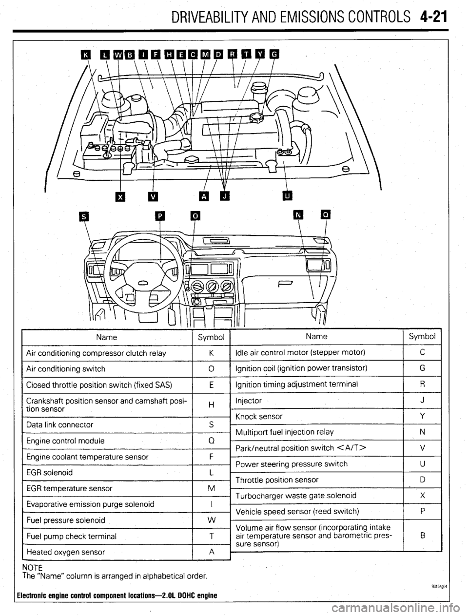
DRIVEABILITYAND EMISSIONS CONTROLS 4-21
Heated oxygen sensor
c
NOTE
The “Name” column is arranged in alphabetical order.
ilectronic engine control component locations-2.01 DOHC engine
Page 165 of 408
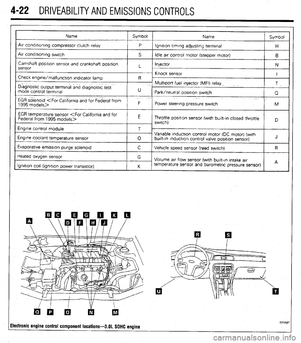
4-22 DRIVEABILITYAND EMISSIONS CONTROLS
Name Symbol
Name Symbol
I
Arr condrttontng compressor clutch relay
P lgnrtton trmrng adjustrng terminal
H
Air condrbonrng swrtch
S Idle arr control motor (stepper motor)
B
Camshaft posrtron sensor and crankshaft posrtron
Injector
N
sensor L
~ Knock sensor
Check engrne/malfunctton rndtcator lamp I
R -
I D~agnostrc output termtnal and dtagnostrc test F- Mujttport fuel qector (MFI) relay _
T
mode control termrnal U
Park/neutral oosrtron swatch
Q
EGR solenoid
1995 models> F
Power steering pressure swatch M
I
EGR temperature sensor
Throttle posrtlon sensor fwrth burlt-In closed throttle
, swrtch)
Engrne control module
Engine coolant temperature sensor
Evaporatrve emrssron purge solenord T
0 Variable tnductton control motor (DC motor) (wrth
burlt-tn rnductron control valve posrtron sensor) J
C Vehrcle speed sensor (reed swatch) R
Heated oxygen sensor
Ignition cot1 (ionrtron Dower transistor) G
Volume arr flow sensor (with burlt-In Intake arr
K temperature sensor and barometric pressure sensor)
I I A
ilectronic engine control component locations-3.01 SOHC engine 93154go7
Page 166 of 408
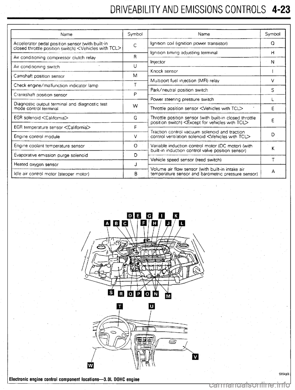
DRIVEABILITYAND EMISSIONS CONTROLS 4-23
Electronic engine
control component locations-3.01 DOHC engine
Page 167 of 408
.
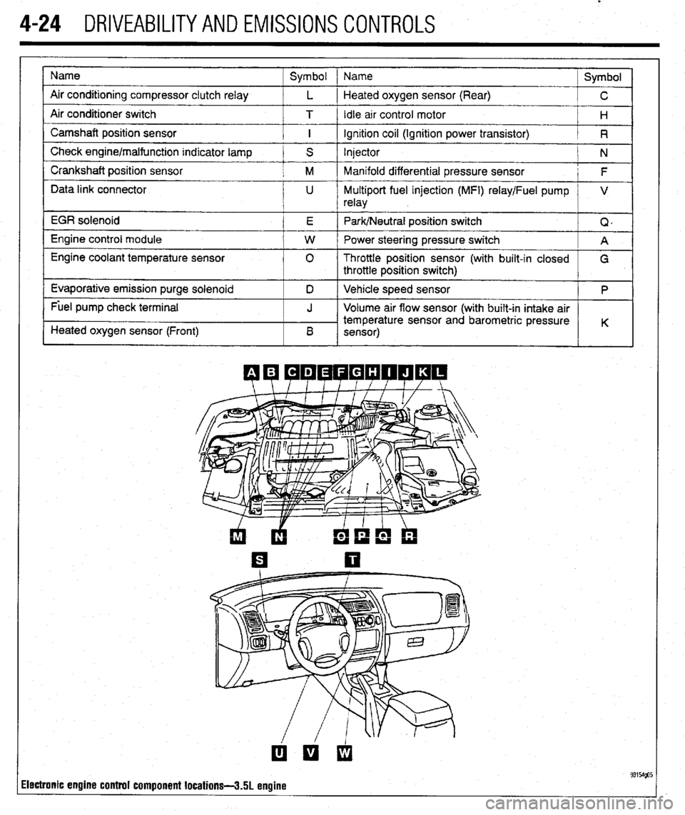
4-24 DRIVEABILITYAND EMISSIONS CONTROLS
Name
Air conditioning compressor clutch relay
Air conditioner switch
Camshaft position sensor
Check engine/malfunction indicator lamp
Crankshaft position sensor
Data link connector
EGR solenoid
Engine control module
Engine coolant temperature sensor
Evaporative emission purge solenoid
Fuel pump check terminal
Heated oxygen sensor (Front) Symbol 1 Name
Symbol
L 1 Heated oxygen sensor (Rear)
C
T / Idle arr control motor
H
I ignition coil (Ignition power transistor)
R
S Injector
N
M Manifold differential pressure sensor
F
U Multiport fuel injection (MFI) relay/Fuel pump V
relay
E Park/Neutral position switch
Q,
W Power steering pressure switch
A
0 Throttle position sensor (with built-in closed
G
throttle position switch)
D Vehicle speed sensor
P
J Volume air flow sensor (with built-in intake air
temperature sensor and barometric pressure
B K
sensor)
ilectronic engine control component locations-3.51 engine
Page 168 of 408
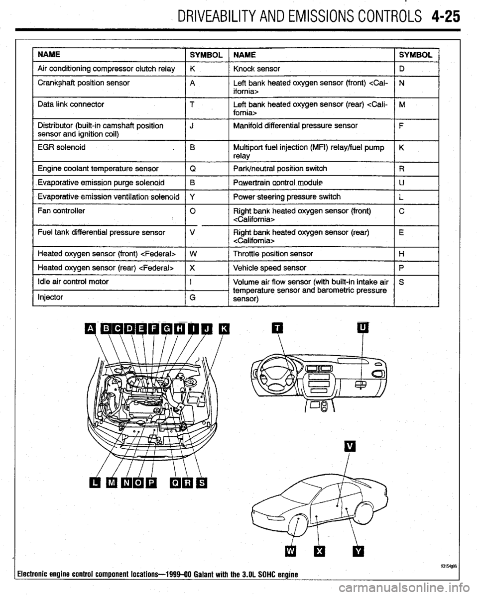
DRIVEABILITYAND EMISSIONS CONTROLS 4-25
NAME
SYMBOL NAME SYMBOL
Air conditioning compressor clutch relay K
Knock sensor D
I Crankshaft position sensor
A Left bank heated oxygen sensor (front)
I I
Data link connector T Left bank heated oxygen sensor (rear)
I Distributor (built-in camshaft position
I J Manifold differential pressure sensor
I F
sensor and ignition coil)
I
EGR solenoid . B Multiport fuel injection (MFI) relay/fuel pump K
relay
1 Engine coolant temperature sensor
IQ 1 Park/neutral position switch IR
Euaporatiue.emission purge solenoid B
Powertraincontrol module LJ
l Evaporatiw5+eiiission ventilation solenoid Y
I Powersteering pressure switch
L
Fan controller 0 Right bank heated oxygen sensor (front) C
Fuel tank differential pressure sensor V Right bank heated oxygen sensor (rear) E
Heated oxygen sensor (front)
I
1 Heated oxygen sensor (rear)
Ip I
Idle air control motor
Injector I
G Volume air flow sensor (with built-in intake air S
temperature sensor and barometric pressure
sensor)
I I
93154@3 lectronic engine control component locations-199940 Galant with the 3.OL SOHC engine
Page 169 of 408
4-26 DRIVEABILITYAND EMISSIONS CONTROLS
The Powertrain Control Module (PCM) monitors
the signals of input and output sensors, some all the
time and others at certain times and processes each
signal. When the PCM notices that an irregularity has
continued for a specified time or longer from when
the irregular signal was initially monitored, the PCM
judges that a malfunction has occurred and will
memorize the malfunction code. The code is then
stored in the memory of the PCM and is accessible
through the data link (diagnostic connector) with the
use of an electronic scan tool or a voltmeter.
CHECK ENGINE/MALFUNCTION
INDICATOR LIGHT
Among the on-board diagnostic items, a check
engine/malfunction indicator light comes on to notify
the driver of a emission control component irregular-
ity. If the irregularity detected returns to normal or the
PCM judges that the component has returned to nor-
mal, the check engine/malfunction indicator light will
be turned off Moreover, if the ignition is turned OFF
and then the engine is restarted, the check
engine/malfunction indicator light will not be turned
on unttl a malfunction is detected.
The check engine/malfunction indicator light will
come on immediately after the ignition switch is
turned ON. The light should stay lit for 5 seconds
and then will go off. This Indicates that the check en-
gine/malfunction indicator lamp is operating nor-
mally. This does not signify a problem with the sys-
tem.
*The check engine/malfunction indicator
lamp will come on when the terminal for the
ignition timing adjustment is shorted to
ground. Therefore, it is not abnormal that the
light comes on even when the terminal for ig-
nition timing is shorted at time of ignition
timing adjustment.
To test the light, perform the following:
1. Turn the ignition switch ON. Inspect the check
engine/malfunction indicator lamp for Illumination.
2. The light should be lit for 5 seconds and then
should go out.
3. If the lamp does not illuminate, check for open
circuit In the harness, blown fuse or blown bulb.
SERVICE PRECAUTIONS
l Before attachrng or detaching the PCM harness
connectors, make sure the ignition switch is OFF and
the negative battery cable is disconnected to avoid
the possibility of damage to the PCM.
l When performing PCM input/output signal di-
agnosis, remove the pin terminal retainer from the
connectors to make it easier to insert tester probes
into the connector.
l When attaching or detaching pin connectors ,
from the PCM, take care not to bend or break any pin
terminals. Check that there are no bends or breaks on
PCM pin terminals before attempting any connec-
tions.
l Before replacing any PCM, perform the PCM
input/output signal diagnosis to make sure the PCM
is functioning properly.
l When measuring supply voltage of PCM-con-
trolled components with a circuit tester, separate 1
tester probe from another. If the 2 tester probes acci-
dentally make contact with each other during mea-
surement, a short circuit WIII result and damage the
PCM.
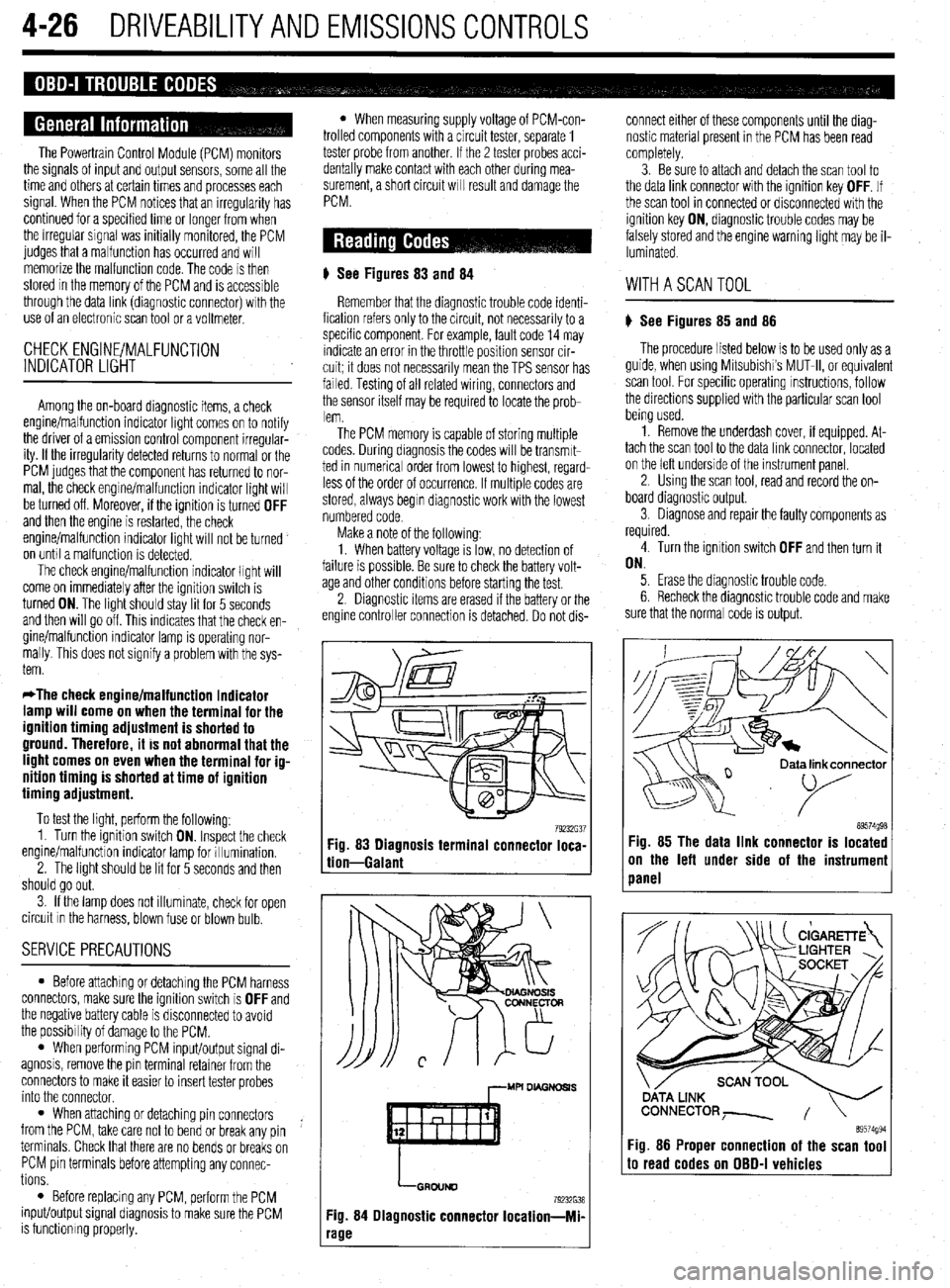
# See Figures 83
and 84
Remember that the diagnostic trouble code identi-
fication refers only to the circuit, not necessarily to a
specific component. For example, fault code 14 may
indicate an error in the throttle position sensor cir-
cuit; it does not necessarily mean the TPS sensor has
failed Testing of all related wiring, connectors and
the sensor itself may be required to locate the prob-
lem.
The PCM memory is capable of storing multiple
codes. During diagnosis the codes will be transmlt-
ted in numerical order from lowest to highest, regard-
less of the order of occurrence. If multiple codes are
stored, always begin diagnostic work with the lowest
numbered code
Make a note of the following:
1. When battery voltage IS low, no detection of
failure is possible. Be sure to check the battery volt-
age and other conditions before starting the test.
2. Diagnostic items are erased if the battery or the
engine controller connection is detached. Do not dis- connect either of these components until the diag-
nostic material present in the PCM has been read
completely.
3. Be sure to attach and detach the scan tool to
the data link connector with the ignition key OFF. If
the scan tool in connected or disconnected with the
ignition key ON, diagnostic trouble codes may be
falsely stored and the engine warning light may be il-
luminated. WITHASCANTOOL
) See Figures 85 and 86
The procedure listed below is to be used only as a
guide, when using Mitsubishi’s MUT-II, or equivalent
scan tool. For specific operating instructions, follow
the directions supplied with the particular scan tool
bemg used.
1. Remove the underdash cover, if equipped. At-
tach the scan tool to the data link connector, located
on the left underside of the instrument panel.
2. Using the scan tool, read and record the on-
board diagnostic output.
3. Diagnose and repair the faulty components as
required
4. Turn the ignition switch OFF and then turn it
ON.
5. Erase the diagnostic trouble code.
6 Recheck the diaanostic trouble code and make
sure that the normal &de is output.
79232G37 89574g98 Fig. 83 Diagnosis terminal connector loca-
tion-Galant Fig. 85 The data link connector is located
on the left under side of the instrumeni
panel
,--MU DL4GNDSl.S
LGRDIJND
79232638
Fig. 84 Diagnostic connector Iocation-Mi-
‘age
ata link connector
89574994 Fig. 86 Proper connection of the scan tool to read codes on OBD-I vehicles
Page 170 of 408
DRIVEABILITYAND EMISSIONS CONTROLS 4-27
WITHOUTASCANTOOL
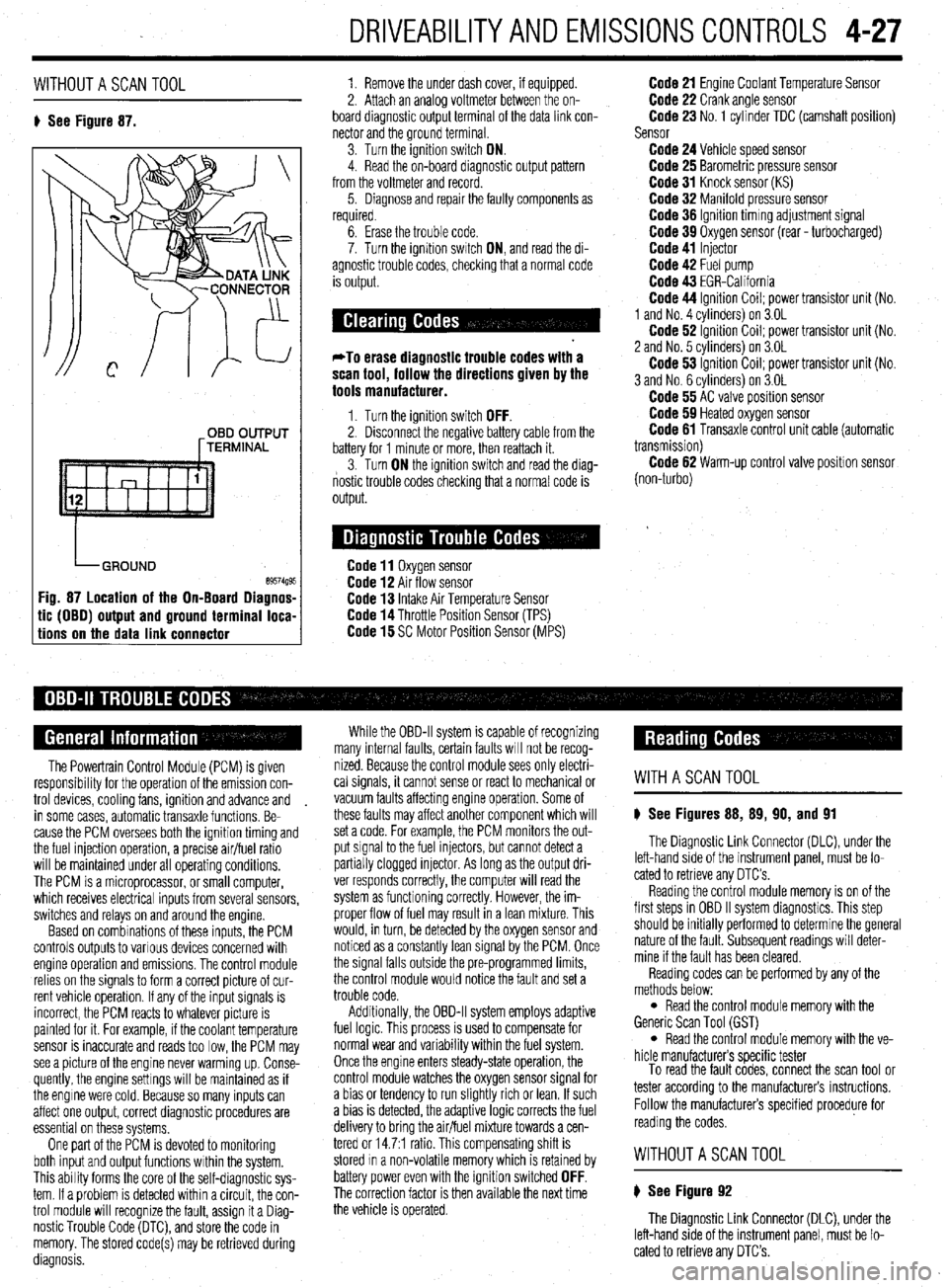
8 See Figure 87. 1. Remove the under dash cover, if equipped.
2. Attach an analoa voltmeter between the on-
board diagnostic outpit terminal of the data link con-
nector and the ground terminal
3. Turn the ignition switch ON.
4. Read the on-board diagnostic output pattern
from the voltmeter and record.
5. Diagnose and repair the faulty components as
required.
OBD OUTPUT
[TERMINAL
tic (OBO) output and ground terminal loca-
tions on the data link connector
6. Erase the trouble code.
7. Turn the ignition swatch ON, and read the di-
agnostic trouble codes, checking that a normal code
is output.
*To erase diagnostic trouble codes with a
scan tool, follow the directions given by the
tools manufacturer.
1. Turn the ignition switch OFF. 2. Disconnect the negative battery cable from the
battery for 1 minute or more, then reattach it.
3. Turn ON the ignition switch and read the diag-
nostic trouble codes checking that a normal code is
output.
Code 11 Oxygen sensor Code 12 Air flow sensor Code 13 Intake Air Temperature Sensor Code 14 Throttle Position Sensor (TPS) Code 15 SC Motor Position Sensor (MPS)
Code 21 Engine Coolant Temperature Sensor Code 22 Crank angle sensor Code 23 No. 1 cylinder TDC (camshaft position)
Sensor
Code 24 Vehicle speed sensor Code 25 Barometric pressure sensor Code 31 Knock sensor (KS) Code 32 Manifold pressure sensor Code 36 Ignition timmg adjustment signal Code 39 Oxygen sensor (rear - turbocharged) Code 41 Injector Code 42 Fuel pump Code 43 EGR-California Code 44 Ignition Coil; power transistor unit (No.
1 and No. 4 cvlinders) on 3.OL
Code 62 ignition Coil; power transistor unit (No.
2 and No. 5 cvlinders) on 3.OL
Code 53 ignition Coil; power transistor unit (No.
3 and No. 6 cylinders) on 3.OL
Code 55 AC valve position sensor Code 59 Heated oxygen sensor Code 61 Transaxle control unit cable (automatic
transmission)
Code 62 Warm-up control valve position sensor
(non-turbo)
The Powertrain Control Module (PCM) is given
responsibrlity for the operation of the emission con-
trol devices, cooling fans, ignition and advance and
in some cases, automatic transaxle functions. Be-
cause the PCM oversees both the ignition timing and
the fuel injection operation, a precise air/fuel ratio
will be maintained under all operating conditions,
The PCM is a microprocessor, or small computer,
which receives electrical inputs from several sensors,
switches and relays on and around the engine.
Based on combinations of these inputs, the PCM
controls outputs to various devices concerned with
engine operation and emissions. The control module
relies on the signals to form a correct picture of cur-
rent vehicle operation. If any of the input signals is
incorrect, the PCM reacts to whatever picture is
painted for it. For example, if the coolant temperature
sensor is inaccurate and reads too low, the PCM may
see a picture of the engine never warming up. Conse-
quently, the engine settings will be maintained as if
the engine were cold. Because so many inputs can
affect one output, correct diagnostic procedures are
essential on these systems,
One part of the PCM is devoted to monitoring
both input and output functions within the system.
This ability forms the core of the self-diagnostic sys-
tem. If a problem is detected within a circuit, the con-
trol module will recognize the fault, assign it a Diag-
nostic Trouble Code (DTC), and store the code in
memory. The stored code(s) may be retrieved during
diagnosis. While the OBD-II system is capable of recognizing
many internal faults, certain faults WIII not be recog-
nized. Because the control module sees only electri-
cal signals, it cannot sense or react to mechanical or
vacuum faults affecting engine operation. Some of
these faults may affect another component which will
set a code. For example, the PCM monitors the out-
put signal to the fuel injectors, but cannot detect a
partially clogged injector. As long as the output dri-
ver responds correctly, the computer will read the
system as functioning correctly. However, the im-
proper flow of fuel may result in a lean mixture. This
would, in turn, be detected by the oxygen sensor and
noticed as a constantly lean signal by the PCM. Once
the signal falls outside the pre-programmed limits,
the control module would notice the fault and set a
trouble code.
Additionally, the OBD-II system employs adaptive
fuel logic. This process is used to compensate for
normal wear and variability within the fuel system.
Once the engine enters steady-state operation, the
control module watches the oxygen sensor signal for
a bias or tendency to run slightly rich or lean. If such
a bias is detected, the adaptive logic corrects the fuel
delivery to bring the air/fuel mixture towards a cen-
tered or 14.7:1 ratio. This compensating shift is
stored In a non-volatile memory which is retained by
battery power even with the ignition switched
OFF. The correction factor is then available the next time
the vehicle is operated.
WITHASCANTOOL
8 See Figures 88, 89, 90, and 91
The Diagnostic Link Connector (DLC), under the
left-hand side of the instrument panel, must be lo-
cated to retrieve any OTC’s
Reading the control module memory is on of the
first steps in OBD II system diagnostics. This step
should be initially performed to determine the general
nature of the fault. Subsequent readings will deter-
mine if the fault has been cleared.
Reading codes can be performed by any of the
methods below:
l Read the control module memory with the
Generic Scan Tool (GST)
l Read the control module memory with the ve-
hicle manufacturers specific tester
To read the fault codes, connect the scan tool or
tester according to the manufacturers instructions.
Follow the manufacturers specified procedure for
reading the codes.
WITHOUTASCANTOOL
8 See Figure 92
The Diagnostic Link Connector (DLC), under the
left-hand side of the instrument panel, must be lo-
cated to retrieve any DTC’s.