MITSUBISHI OUTLANDER SPORT 2014 3.G Owners Manual
Manufacturer: MITSUBISHI, Model Year: 2014, Model line: OUTLANDER SPORT, Model: MITSUBISHI OUTLANDER SPORT 2014 3.GPages: 388, PDF Size: 20.04 MB
Page 221 of 388
Forward Collision Mitigation System (FCM)*7-58 Starting and driving
7
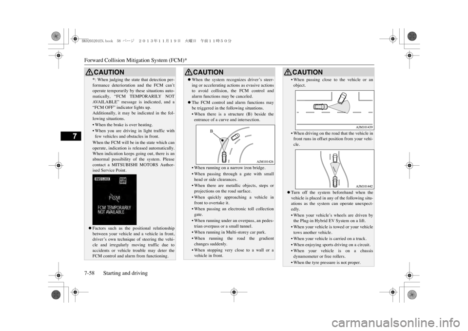
*: When judging the state that detection per-formance deterioration and the FCM can’toperate temporarily by these situations auto-matically, “FCM TEMPORARILY NOTAVA I L A B L E ” m e s s a g e i s i n d i c a t e d , a n d a“FCM OFF” indicator lights up.Additionally, it may be indicated in the fol-lowing situations.•When the brake is over heating.•When you are driving in light traffic withfew vehicles and obs
tacles in front.
When the FCM will be in the state which canoperate, indication is released automatically.When indication keeps going out, there is anabnormal possibility of the system. Pleasecontact a MITSUBISHI MOTORS Author-ised Service Point.�zFactors such as the positional relationshipbetween your vehicle and a vehicle in front,driver’s own technique of steering the vehi-cle and irregularly moving traffic due toaccidents or vehicle trouble may deter theFCM control and alarm from functioning.CAUTION
�zWhen the system recognizes driver’s steer-ing or accelerating actions as evasive actionsto avoid collision, the FCM control andalarm functions may be canceled.�zThe FCM control and alarm functions maybe triggered in the following situations.•When there is a structure (B) beside theentrance of a curve and intersection.•When running on a na
rrow iron bridge.
•When passing through a gate with smallhead or side clearances.•When there are metallic objects, steps orprojections on the road surface.•When quickly approaching a vehicle infront to overtake it.•When passing an electronic toll collectiongate.•When running under an
overpass, an pedes-
trian overpass or a small tunnel.•When running in Multi-storey car park.•When running the road the gradientchanges suddenly.•When stopping very close to a wall or avehicle in front.CAUTION
B
•When passing close to the vehicle or anobject.•When driving on the road that the vehicle infront runs in offset
position from your vehi-
cle.
�zTurn off the system beforehand when thevehicle is placed in a
ny of the following situ-
ations as the system can operate unexpect-edly.•When your vehicle’s wheels are driven bythe Plug-in Hybrid EV System on a lift.•When your vehicle is towed or your vehicletows another vehicle.•When your vehicle is carried on a truck.•When enjoying sports driving on a circuit.•When your vehicle is on a chassisdynamometer or free rollers.•When the tyre pressure is not proper. CAUTION
BK0203201EN.book 58 ページ 2013年11月19日 火曜日 午前11時50分
Page 222 of 388
Forward Collision Mitigation System (FCM)*
Starting and driving 7-59
7
E00635601062
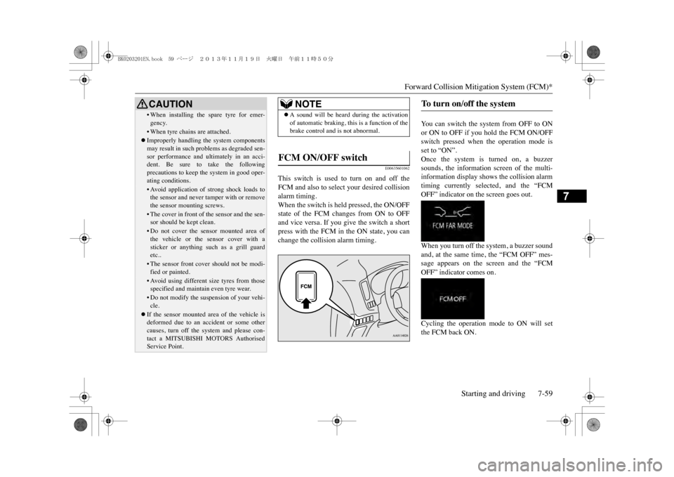
This switch is used to turn on and off theFCM and also to select your desired collisionalarm timing.When the switch is held pressed, the ON/OFFstate of the FCM changes from ON to OFFand vice versa. If you give the switch a shortpress with the FCM in the ON state, you canchange the collision alarm timing.
Yo u c a n s w i t c h t h e s y s t e m f r o m O F F t o O Nor ON to OFF if you hold the FCM ON/OFFswitch pressed when the operation mode isset to “ON”.Once the system is turned on, a buzzersounds, the information screen of the multi-information display shows the collision alarmtiming currently selected, and the “FCMOFF” indicator on the screen goes out.When you turn off the system, a buzzer soundand, at the same time, the “FCM OFF” mes-sage appears on the screen and the “FCMOFF” indicator comes on.Cycling the operation mode to ON will setthe FCM back ON.
•When installing the spare tyre for emer-gency.•When tyre chains are attached.�zImproperly handling the system componentsmay result in such problems as degraded sen-sor performance and ultimately in an acci-dent. Be sure to take the followingprecautions to keep the system in good oper-ating conditions.•Avoid application of
strong shock loads to
the sensor and never tamper with or removethe sensor mounting screws.• The cover in front of the sensor and the sen-sor should be kept clean.•Do not cover the sensor mounted area ofthe vehicle or the sensor cover with asticker or anything such as a grill guardetc..•The sensor front cove
r should not be modi-
fied or painted.•Avoid using different
size tyres from those
specified and maintain even tyre wear.•Do not modify the suspension of your vehi-cle.
�zIf the sensor mounted area of the vehicle isdeformed due to an acci
dent or some other
causes, turn off the system and please con-tact a MITSUBISHI MOTORS AuthorisedService Point.CAUTION
NOTE
�zA sound will be heard during the activationof automatic braking, this is a function of thebrake control and is not abnormal.
FCM ON/OFF switch
To t u r n o n / o f f t h e s y s t e m
BK0203201EN.book 59 ページ 2013年11月19日 火曜日 午前11時50分
Page 223 of 388
Lane Departure Warning (LDW)*7-60 Starting and driving
7
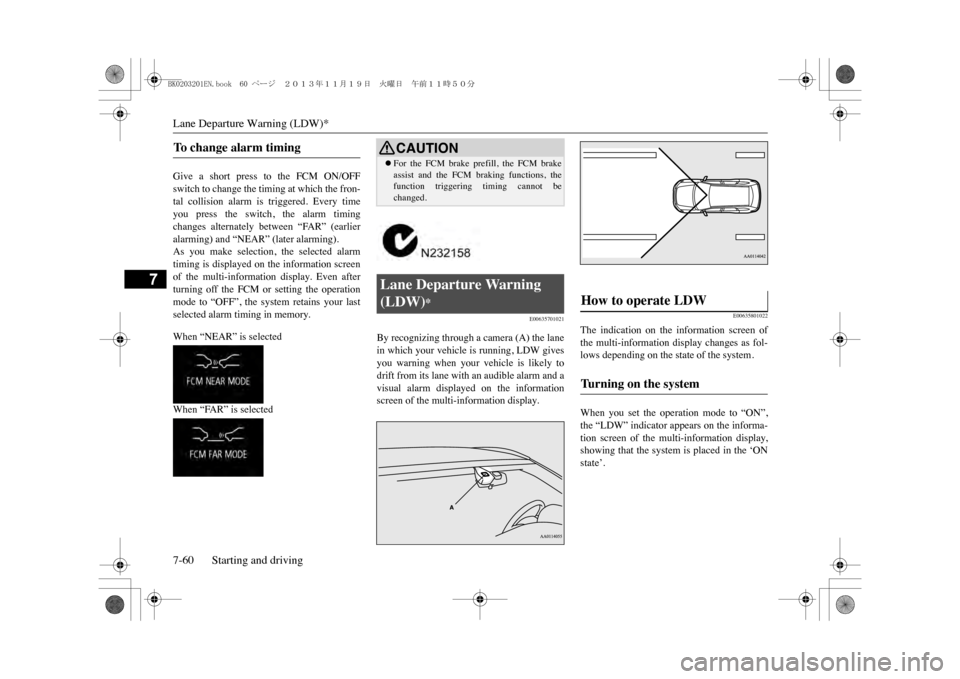
Give a short press to the FCM ON/OFFswitch to change the timing at which the fron-tal collision alarm is triggered. Every timeyou press the switch, the alarm timingchanges alternately between “FAR” (earlieralarming) and “NEAR” (later alarming).As you make selection, the selected alarmtiming is displayed on the information screenof the multi-information display. Even afterturning off the FCM or setting the operationmode to “OFF”, the sy
stem retains your last
selected alarm timing in memory.When “NEAR” is selectedWhen “FAR” is selected
E00635701021
By recognizing through a camera (A) the lanein which your vehicle is running, LDW givesyou warning when your vehicle is likely todrift from its lane with an audible alarm and avisual alarm displayed on the informationscreen of the multi-information display.
E00635801022
The indication on the information screen ofthe multi-information display changes as fol-lows depending on the state of the system.When you set the operation mode to “ON”,the “LDW” indicator appears on the informa-tion screen of the multi-information display,showing that the system is placed in the ‘ONstate’.
To c h a n g e a l a r m t i m i n g
CAUTION�zFor the FCM brake prefill, the FCM brakeassist and the FCM braking functions, thefunction triggering timing cannot bechanged.
Lane Departure Warning (LDW)
*
How to operate LDW
Tu r n i n g o n t h e s y s t e m
BK0203201EN.book 60 ページ 2013年11月19日 火曜日 午前11時50分
Page 224 of 388
Lane Departure Warning (LDW)*
Starting and driving 7-61
7
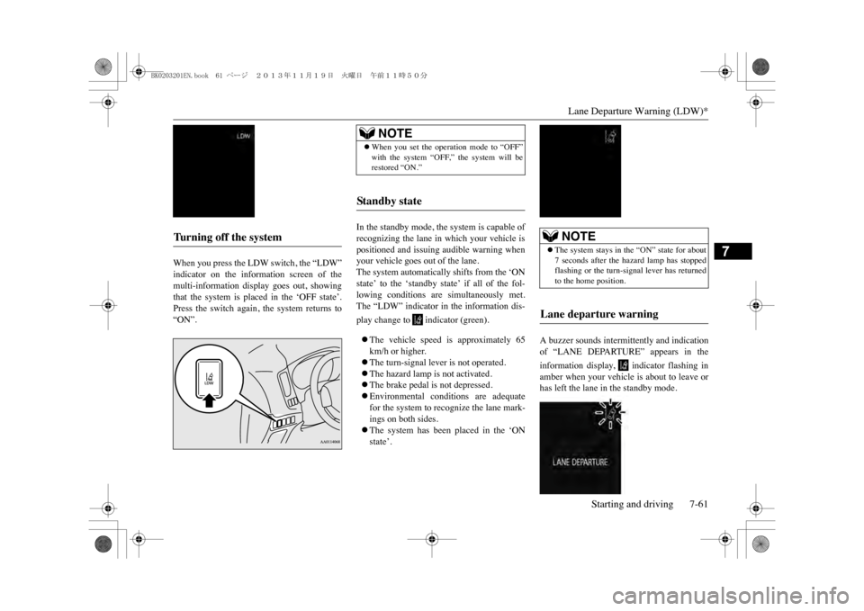
When you press the LDW switch, the “LDW”indicator on the information screen of themulti-information display goes out, showingthat the system is placed in the ‘OFF state’.Press the switch again, the system returns to“ON”.
In the standby mode, the system is capable ofrecognizing the lane in which your vehicle ispositioned and issuing audible warning whenyour vehicle goes out of the lane.The system automatically shifts from the ‘ONstate’ to the ‘standby state’ if all of the fol-lowing conditions are simultaneously met.The “LDW” indicator in the information dis-play change to indicator (green).�zThe vehicle speed is approximately 65km/h or higher.�zThe turn-signal lever is not operated.�zThe hazard lamp is not activated.�zThe brake pedal is not depressed.�zEnvironmental conditions are adequatefor the system to recognize the lane mark-ings on both sides.�zThe system has been placed in the ‘ONstate’.
A buzzer sounds intermittently and indicationof “LANE DEPARTURE” appears in theinformation display, indicator flashing inamber when your vehicle is about to leave orhas left the lane in the standby mode.
Tu r n i n g o f f t h e s y s t e m
NOTE
�zWhen you set the operation mode to “OFF”with the system “OFF,” the system will berestored “ON.”
Standby state
NOTE
�zThe system stays in the “ON” state for about7 seconds after the hazard lamp has stoppedflashing or the turn-si
gnal lever has returned
to the home position.
Lane departure warning
BK0203201EN.book 61 ページ 2013年11月19日 火曜日 午前11時50分
Page 225 of 388
Lane Departure Warning (LDW)*7-62 Starting and driving
7
E00635901023
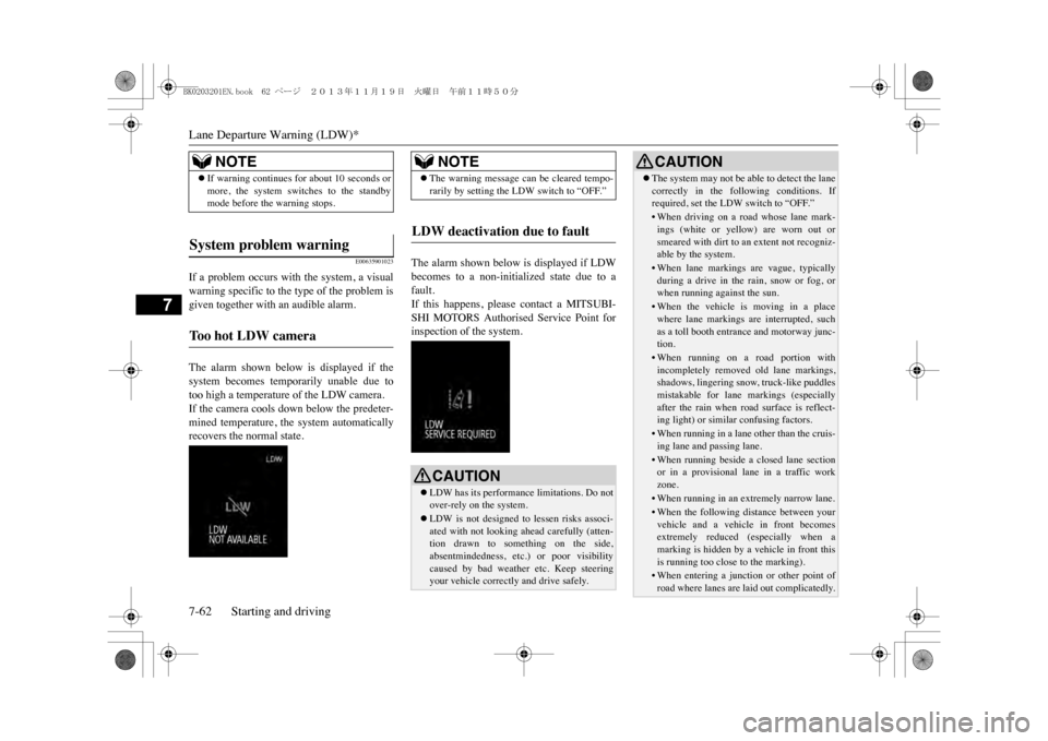
If a problem occurs with the system, a visualwarning specific to the type of the problem isgiven together with an audible alarm.The alarm shown below is displayed if thesystem becomes temporarily unable due totoo high a temperature of the LDW camera.If the camera cools down below the predeter-mined temperature, the system automaticallyrecovers the normal state.
The alarm shown below is displayed if LDWbecomes to a non-initialized state due to afault.If this happens, please contact a MITSUBI-SHI MOTORS Authorised Service Point forinspection of the system.
NOTE
�zIf warning continues
for about 10 seconds or
more, the system switches to the standbymode before the warning stops.
System problem warning
To o h o t L D W c a m e r a
NOTE
�zThe warning message can be cleared tempo-rarily by setting the LDW switch to “OFF.”
LDW deactivation due to fault
CAUTION�zLDW has its performance limitations. Do notover-rely on the system.�zLDW is not designed to
lessen risks associ-
ated with not looking ah
ead carefully (atten-
tion drawn to something on the side,absentmindedness, etc.) or poor visibilitycaused by bad weather etc. Keep steeringyour vehicle correctly and drive safely.
�zThe system may not be able to detect the lanecorrectly in the following conditions. Ifrequired, set the LDW switch to “OFF.”•When driving on a road whose lane mark-ings (white or yellow) are worn out orsmeared with dirt to an extent not recogniz-able by the system.•When lane markings are vague, typicallyduring a drive in the rain, snow or fog, orwhen running against the sun.•When the vehicle is moving in a placewhere lane markings are interrupted, suchas a toll booth entrance and motorway junc-tion.•When running on a road portion withincompletely removed old lane markings,shadows, lingering snow, truck-like puddlesmistakable for lane markings (especiallyafter the rain when road surface is reflect-ing light) or simila
r confusing factors.
•When running in a lane other than the cruis-ing lane and
passing lane.
•When running beside a closed lane sectionor in a provisional lane in a traffic workzone.•When running in an extremely narrow lane.•When the following distance between yourvehicle and a vehicle in front becomesextremely reduced (especially when amarking is hidden by a vehicle in front thisis running too close to the marking).•When entering a juncti
on or other point of
road where lanes are laid out complicatedly.CAUTION
BK0203201EN.book 62 ページ 2013年11月19日 火曜日 午前11時50分
Page 226 of 388
Reversing sensor system*
Starting and driving 7-63
7
E00615500374
This system operates when you are backingthe vehicle. It uses corner and back sensors todetect an obstacle and the information screenin the multi information display and thebuzzer to inform you of the approximate dis-tance to the obstacle.
E00615601473
The detection areas of the corner and backsensors are limited to those shown in theillustration. Moreover, the sensors are unableto detect low or thin objects or objects nearthe rear bumper. Thus, make sure to check thesurroundings as you operate the vehicle in asafe manner.There are two corner sensors (A) at the cor-ners of the rear bumper, and two back sensors(B) in the centre of the rear bumper.
•When passing a road section where thenumber of lanes increases/decreases ormultiple lanes are crossing each other.•When the lane is marked by double or oth-erwise special lines.•When driving on a winding or rough road.•When driving on a sli
ppery road covered by
rain water, snow, ice, etc.•When passing through a place where thebrightness suddenly ch
anges, like the inlet
or outlet of a tunnel.•When turning steep curves.•When the road surface is reflecting the lightshining from the direction opposite to therunning direction.•Vehicle largely lurches when it is runningover steps or other irregularities of the roadsurface.•When the headlamp illumination is inade-quate because of contaminated or deterio-rated lenses or improperly aimedheadlamps.•When the vehicle is leaning much to oneside due to heavy l
uggage on it or improp-
erly adjusted tyre pressures.•When oncoming vehicl
es’ headlamps shine
the LDW camera.•When the vehicle is equipped with non-standard tyres (incl
uding excessively worn
tyres), uses snow tr
action device (tyre
chains), or has non-specified componentssuch as a modified suspension.CAUTION
•When the windscreen is covered with rainwater, snow, dust, etc.
�zFollow the instructions given below to keepyour LDW in good operating conditions. •Always keep the windscreen clean.•Avoid applying a str
ong shock or pressure
to the LDW camera. Do not attempt to dis-assemble it.•Disturbing the installation of the LDWcamera or its removal is under no circum-stances permitted. The camera has beenprecisely oriented at the factory.• Do not put anything like a sticker on thearea in front of the LDW camera lens of thewindscreen.•Use only MITSUBISHI MOTORS GENU-INE Parts when replacing the windscreenwipers.
Reversing sensor system
*
CAUTION
CAUTION�zThe reversing sensor system assists you indetermining the approximate distancebetween the vehicle and an obstacle locatedbehind the vehicle. It has limitations in termsof detectable areas and objects, and may notproperly detect some objects. Therefore, donot place excessive confidence in the revers-ing sensor system, and operate the vehicle ascarefully as you would
a vehicle without this
system.�zMake sure to check the surroundings withyour own eyes to ensure safety. Do not oper-ate the vehicle by relying on the reversingsensor system alone.
Obstacle detection areas
Corner and back sensor locations
BK0203201EN.book 63 ページ 2013年11月19日 火曜日 午前11時50分
Page 227 of 388
Reversing sensor system*7-64 Starting and driving
7
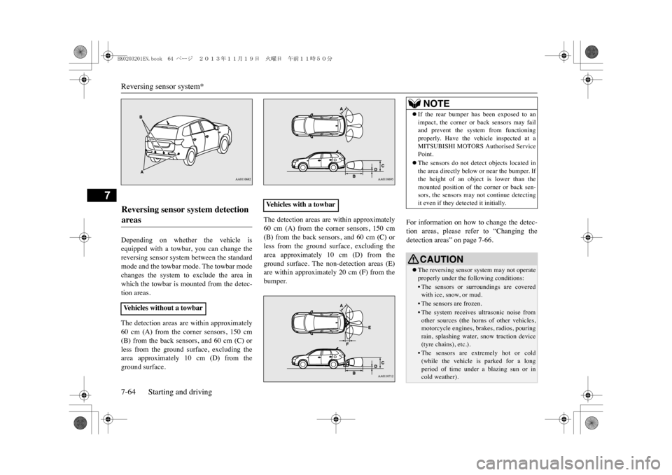
Depending on whether the vehicle isequipped with a towbar, you can change thereversing sensor system between the standardmode and the towbar mode. The towbar modechanges the system to exclude the area inwhich the towbar is mounted from the detec-tion areas.The detection areas are within approximately60 cm (A) from the corner sensors, 150 cm(B) from the back sensors, and 60 cm (C) orless from the ground surface, excluding thearea approximately 10 cm (D) from theground surface.
The detection areas are within approximately60 cm (A) from the corner sensors, 150 cm(B) from the back sensors, and 60 cm (C) orless from the ground surface, excluding thearea approximately 10 cm (D) from theground surface. The non-detection areas (E)are within approximately 20 cm (F) from thebumper.
For information on how to change the detec-tion areas, please refer to “Changing thedetection areas” on page 7-66.
Reversing sensor system detection areas
Ve h i c l e s w i t h o u t a t o w b a r
Ve h i c l e s w i t h a t o w b a r
NOTE
�zIf the rear bumper has been exposed to animpact, the corner or back sensors may failand prevent the system from functioningproperly. Have the vehicle inspected at aMITSUBISHI MOTORS Authorised ServicePoint.�zThe sensors do not detect objects located inthe area directly below or near the bumper. Ifthe height of an object is lower than themounted position of the corner or back sen-sors, the sensors may not continue detectingit even if they detected it initially.CAUTION�zThe reversing sensor
system may not operate
properly under the following conditions:•The sensors or surroundings are coveredwith ice, snow, or mud.•The sensors are frozen.•The system receives ultrasonic noise fromother sources (the horns
of other vehicles,
motorcycle engines, brakes, radios, pouringrain, splashing water,
snow traction device
(tyre chains), etc.).•The sensors are extremely hot or cold(while the vehicle is parked for a longperiod of time under a blazing sun or incold weather).
BK0203201EN.book 64 ページ 2013年11月19日 火曜日 午前11時50分
Page 228 of 388
Reversing sensor system*
Starting and driving 7-65
7
E00615701823
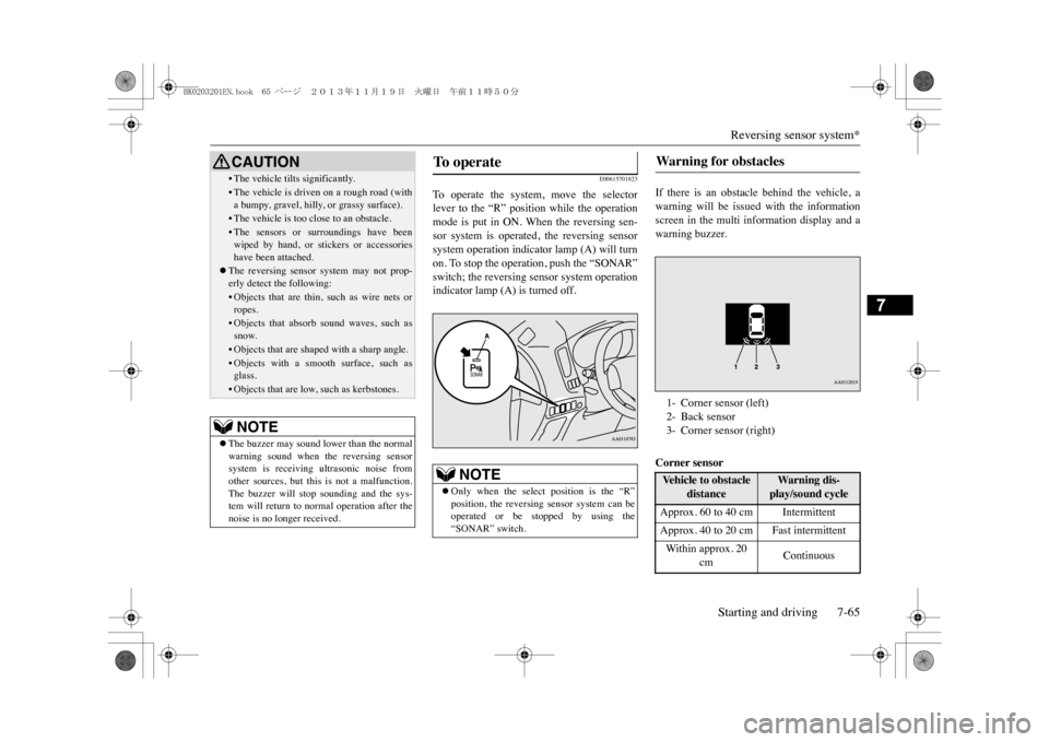
To o p e r a t e t h e s y s t e m , m o v e t h e s e l e c t o rlever to the “R” position while the operationmode is put in ON. When the reversing sen-sor system is operated, the reversing sensorsystem operation indicator lamp (A) will turnon. To stop the operation, push the “SONAR”switch; the reversing sensor system operationindicator lamp (A) is turned off.
If there is an obstacle behind the vehicle, awarning will be issued with the informationscreen in the multi information display and awarning buzzer.Corner sensor
• The vehicle tilts significantly.•The vehicle is driven on a rough road (witha bumpy, gravel, hilly, or grassy surface).•The vehicle is too close to an obstacle.•The sensors or surroundings have beenwiped by hand, or stic
kers or accessories
have been attached.
�zThe reversing sensor system may not prop-erly detect the following:•Objects that are thin, such as wire nets orropes.•Objects that absorb sound waves, such assnow.•Objects that are shaped with a sharp angle.•Objects with a smooth surface, such asglass.•Objects that are low, such as kerbstones.NOTE
�zThe buzzer may sound lower than the normalwarning sound when
the reversing sensor
system is receiving ultrasonic noise fromother sources, but this is not a malfunction.The buzzer will stop sounding and the sys-tem will return to normal operation after thenoise is no longer received.CAUTION
To o p e r a t e
NOTE
�zOnly when the select position is the “R”position, the reversing sensor system can beoperated or be stopped by using the“SONAR” switch.
Warni ng f or obst acl es
1- Corner sensor (left)2- Back sensor3- Corner sensor (right)Ve h i c l e t o o b s t a c l e
distance
Warn i ng di s -play/sound cycle
Approx. 60 to 40 cm IntermittentApprox. 40 to 20 cm Fast intermittentWi t h in app r ox . 20
cm
Continuous
BK0203201EN.book 65 ページ 2013年11月19日 火曜日 午前11時50分
Page 229 of 388
Reversing sensor system*7-66 Starting and driving
7
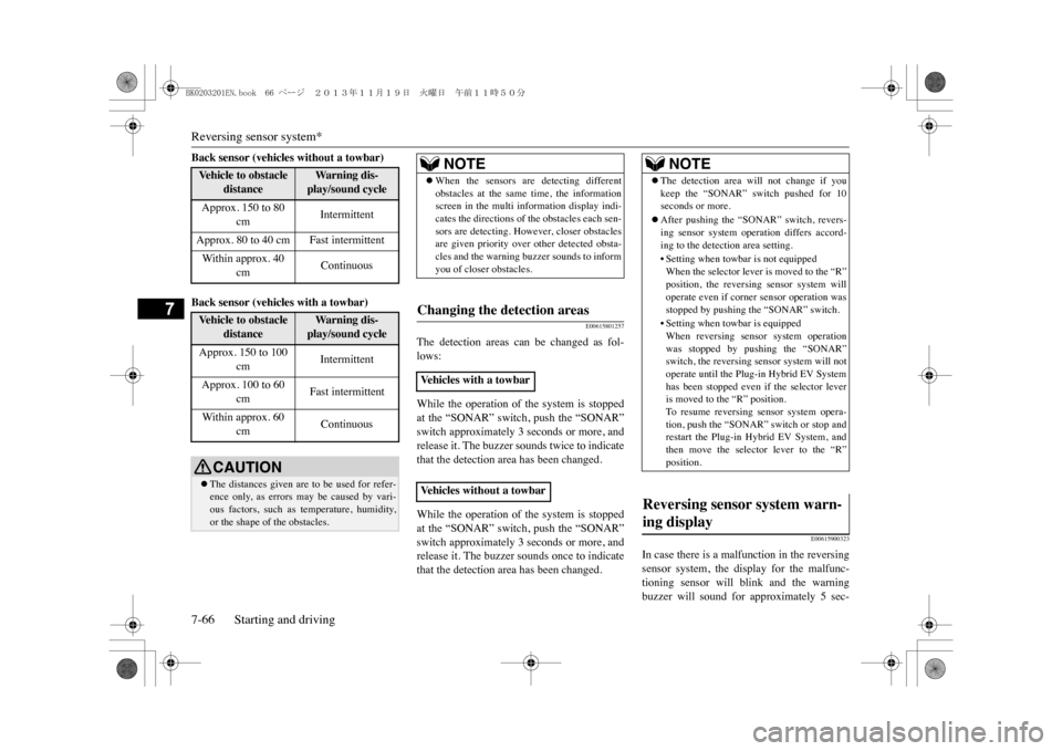
Back sensor (vehicles without a towbar)Back sensor (vehicles with a towbar)
E00615801257
The detection areas can be changed as fol-lows:While the operation of the system is stoppedat the “SONAR” switch, push the “SONAR”switch approximately 3 seconds or more, andrelease it. The buzzer sounds twice to indicatethat the detection area has been changed.While the operation of the system is stoppedat the “SONAR” switch, push the “SONAR”switch approximately 3 seconds or more, andrelease it. The buzzer sounds once to indicatethat the detection area has been changed.
E00615900323
In case there is a malfunction in the reversingsensor system, the display for the malfunc-tioning sensor will blink and the warningbuzzer will sound for approximately 5 sec-
Ve h i c l e t o o b s t a c l e
distance
Wa r n i n g d i s -play/sound cycle
Approx. 150 to 80
cm
Intermittent
Approx. 80 to 40 cm Fast intermittentWi t hi n a ppr o x. 40
cm
Continuous
Ve h i c l e t o o b s t a c l e
distance
Wa r n i n g d i s -play/sound cycle
Approx. 150 to 100
cm
Intermittent
Approx. 100 to 60
cm
Fast intermittent
Wi t hi n a ppr o x. 60
cm
Continuous
CAUTION�zThe distances given are to be used for refer-ence only, as errors may be caused by vari-ous factors, such as temperature, humidity,or the shape of the obstacles.
NOTE
�zWhen the sensors are detecting differentobstacles at the same time, the informationscreen in the multi information display indi-cates the directions of the obstacles each sen-sors are detecting. However, closer obstaclesare given priority over other detected obsta-cles and the warning buzzer sounds to informyou of closer obstacles.
Changing the detection areas
Ve h i c l e s w i t h a t o w b a rVe h i c l e s w i t h o u t a t o w b a r
NOTE
�zThe detection area will not change if youkeep the “SONAR” switch pushed for 10seconds or more.�zAfter pushing the “SONAR” switch, revers-ing sensor system operation differs accord-ing to the detection area setting.•Setting when towbar is not equippedWhen the selector lever is moved to the “R”position, the reversi
ng sensor system will
operate even if corner sensor operation wasstopped by pushing the “SONAR” switch.•Setting when towbar is equippedWhen reversing sensor system operationwas stopped by pushing the “SONAR”switch, the reversing sensor system will notoperate until the Plug-
in Hybrid EV System
has been stopped even if the selector leveris moved to the “R” position.To r e s u m e r e v e r s i n g s e n s o r s y s t e m o p e r a -tion, push the “SONAR” switch or stop andrestart the Plug-in Hybrid EV System, andthen move the selector lever to the “R”position.
Reversing sensor system warn-ing display
BK0203201EN.book 66 ページ 2013年11月19日 火曜日 午前11時50分
Page 230 of 388
Rear-view camera*
Starting and driving 7-67
7
onds. Even after the buzzer and display hasstopped warning, the indicator lamp (A) on“SONAR” switch will continue blinking untilthe system reverts to the normal state. Havethe vehicle inspected at a MITSUBISHIMOTORS Authorised Service Point.
E00618401603
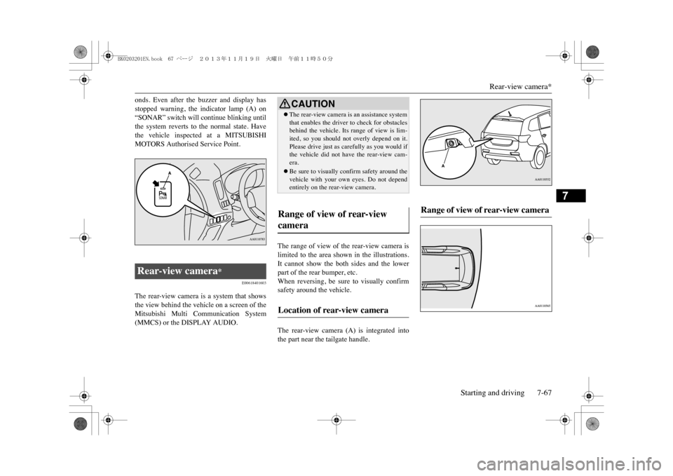
The rear-view camera is a system that showsthe view behind the vehicle on a screen of theMitsubishi Multi Communication System(MMCS) or the DISPLAY AUDIO.
The range of view of the rear-view camera islimited to the area shown in the illustrations.It cannot show the both sides and the lowerpart of the rear bumper, etc.When reversing, be sure to visually confirmsafety around the vehicle.The rear-view camera (A) is integrated intothe part near the tailgate handle.
Rear-view camera
*
CAUTION�zThe rear-view camera is an assistance systemthat enables the driver
to check for obstacles
behind the vehicle. Its
range of view is lim-
ited, so you should not overly depend on it.Please drive just as car
efully as you would if
the vehicle did not have the rear-view cam-era.�zBe sure to visually confirm safety around thevehicle with your own
eyes. Do not depend
entirely on the rear-view camera.
Range of view of rear-view camera
Location of rear-view camera
Range of view of rear-view camera
BK0203201EN.book 67 ページ 2013年11月19日 火曜日 午前11時50分